1 Introduction
Several industrial sectors, in particular the aerospace and automotive fields, depend on the use of composite materials in their production because these materials are lightweight and have a higher strength and stiffness to mass ratio compared to metallic structures [1]. The manufacturing of composite materials can be realized by several industrial technologies, like the Liquid Composite Manufacturing (LCM). This technology is often used for the manufacturing of composite parts of complex geometries because it ensures a good compromise in terms of repeatability, production rates, quality and price [2,3]. The LCM technology has two main phases: the first one depends on the forming of a fabric according to a defined mold geometry and the second one is based on the injection of a resin inside the formed fabric, so that the resin is polymerized in order to produce the final composite part. During the preforming phase, the fabric undergoes several mechanical stresses: biaxial tensile stress, shear, bending, compaction and friction. The cumulative effect of these stresses leads to the appearance of many types of defects at different scales of the fabric, as shown in Fig. 1.
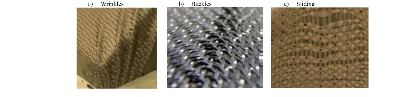
Fig. 1. Examples of different types of forming defects.
Wrinkles is one of the most known defects which happen at the macroscopic scale (fabric scale). This defect has been wildly studied in the scientific literature by several numerical [4,5] and experimental studies [6,7]. On the other hand, the mesoscopic defects of buckles and sliding are less studied and still not fully understood. The appearance of these defects leads to a change in the local density of yarns and their orientations, during the forming phase. Thus, the fabric heterogeneity is no longer the same and the impregnation is not homogenous through the fabric structure [8]. Consequently, the mechanical properties of composite parts may be significantly impacted [9,10,11]. It is therefore important to study these defects and understand their mechanisms of appearance. Sliding defect has been studied by Labanieh et al. [12], who focused on the mechanisms of sliding during the forming of a woven carbon fabric by a hemispheric shape. This defect has also been studied by Gatouillat et al. [13] who proposed an analytical hypoplastic model to describe the sliding defects. Buckles defects has received little attention in the literature, especially for woven fabrics. Capelle et al. [14] have studied this type of defects and proposed a specific blank-holder’s geometry for the forming of a flax woven fabric. Their strategy reduced, and sometimes removed, the occurrence of buckles. However, the strategy they proposed cannot be used for carbon and glass woven fabrics as they are less homogenous than the flax. In addition, their study does not identify the deformation mechanisms, involved during in the appearance of the buckles. Hence, another complementary study was launched by Tephany et al. [15] in which they designed and built an experimental bench to investigate the mechanisms of buckles appearance during the forming of flax woven fabrics. the same bench, which was developed in our lab, was used by Salem et al. [16] who studied the buckle defects of woven fabrics forming. They established a numerical model, based on Lagrange assumptions, to predict the buckles as a function of the transverse yarn’s curvature radius, during the in-plane bending of the fabric. However, the bench they used was limited and cannot simulate the real conditions of an LCM process. For example, it cannot generate all types of defects, such as sliding. In addition, it does not ensure all the boundary conditions of an LCM process and does not enable to adjust the experimental parameters that have an influence on the defect’s appearance, such as the number of longitudinal yarns during the displacement. Subsequently, the present paper follows up the first version of the bench, used in [14,15,16] and presents a new experimental machine with several modifications. Due to this machine, a new strategy for studying woven fabric preforming defects is presented. This strategy is based on two main steps: the first one is the study of the mechanisms underlying the appearance of the preforming defects, and the second one focuses on the influence of these defects, as a function of their amplitudes, on the mechanical properties of composite materials. For the second step, the machine should enable to generate many calibrated defects in fabric samples. These samples are then used to manufacture composite samples with calibrated defects, in order to test and characterize them.
2 Formation mechanisms of buckles and sliding defects.
In order to achieve the goals of this study, the machine should ensure the same boundary conditions and mechanisms that happen during an LCM process, which are presented hereafter: during the forming of a woven fabric by a specific experimental device [17,18] the movement of the punch leads to a displacement of the longitudinal yarns that are in contact with the triple point of the punch. The displacement of these yarns leads to an in-plan-bending of the transverse ones, due to the cohesion between the two networks of yarns (wrap and weft). This movement induces a symmetrical shear of the transverse yarns with a continuous increase in the shear angle (α°), as shown in Fig. 2.
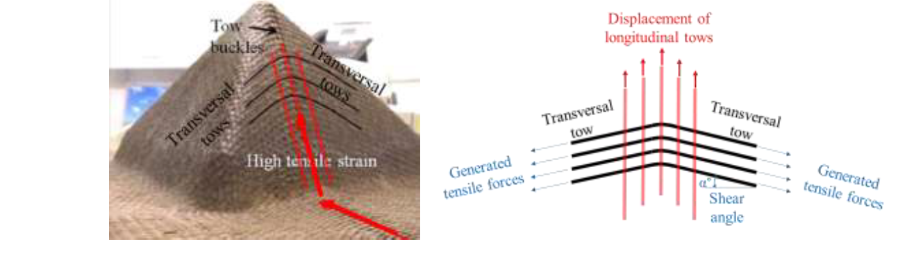
Fig. 2. Formation mechanisms of preforming defects. [18]
After a defined shear angle value, an out-of-plane bending of the transverse yarns starts to appear and forms the buckle defects. When the traction forces applied on the longitudinal yarns become greater than the fabric cohesion, a sliding, which is sometimes called weave pattern heterogeneity, can be observed, as illustrated in Fig. 1. Thus, weave pattern heterogeneity (sliding) and buckle defects are concomitant. In other words, the appearance of one or both defects, depends on the fabric cohesion, the biaxial tension and the boundary conditions.
3 Design and implementation of the machine
The machine should adopt the same kinetics as an LCM preforming process, with the same boundary conditions and the same stresses that the fabric undergoes: displacement, tension, compression and friction. For this reason, two sample fixation methods were proposed in order to generate two types of defects: buckles and sliding. The first method is called tight sample fixation (T). In this method, the yarns of a fabric sample are completely tightened between two metallic jaws, upper and lower, without any possibility of movement of yarns between the jaws, as shown in Fig. 3,a.
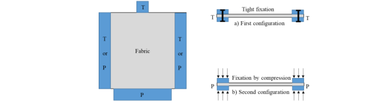
Fig. 3. Different methods of sample fixation.
In the second method, the sample is maintained by compression between two jaws (Fig. 3,b). In this case, a tension is applied on the yarns through a normal pressure (P) so that the yarns can slide and/or rotate between the jaws when the transverse yarns are submitted to a longitudinal displacement. This configuration represents the most common boundary condition of LCM processes. The two fixation methods should make it possible to generate both buckles and sliding defects. Based on this vision, the machine was designed and equipped with four electrical axes (two longitudinal axes: Y+ and Y- and two transverse ones: X+ and X-). The axes can be individually ordered either by a force command, or a displacement command with different speeds. In addition, each axis was equipped with a displacement sensor, a force sensor and two position sensors to define the beginning and the end of the axis stroke. Moreover, a special LabVIEW program was developed to command the machine and to ensure the acquisition of different parameters values, such as the traction forces, the speed and position of each axis. The Fig. 4 presents a photo of the bench after design and building.
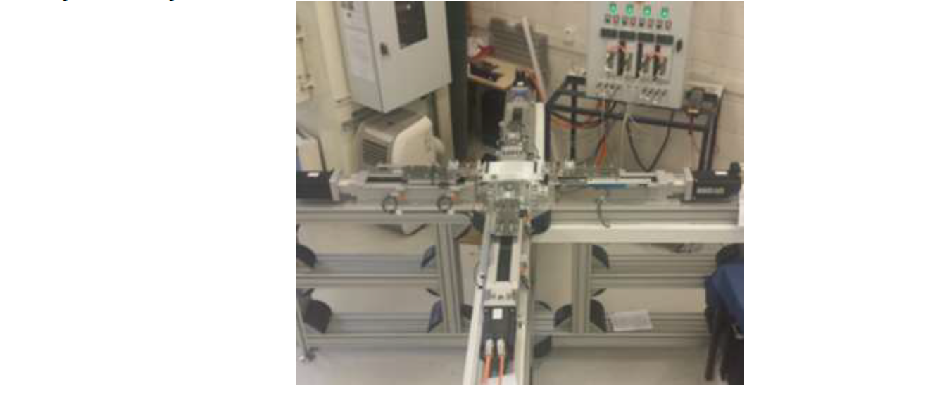
Fig. 4. The bench developed to reproduce mesoscopic defects.
4 Tests and results
Depending on the different modes of command and the different boundary conditions as well as the fabric cohesion, it would be possible to generate different types of calibrated defects. Therefore, many preliminary tests were conducted in order to define the experimental parameters values that correspond to the appearance of each type of defects. Several parameters were tested such as the number of the clamped yarns (which represents the yarns width), the yarn displacement, the type of sample fixation (pressure (P) or tight fixation (T)), the tension of yarns and the direction of displacement (weft or warp direction). Each parameter was changed several times in order to find the optimal value that corresponds to the appearance of each type of defect. Then, several tests were repeated with these values to ensure the reliability of results. In order to respect the length of this paper, as defined in the template, we only present the results corresponding to the generation of one type of defects (buckles) for one type of fabric, denoted interlock G1151® which is a carbon powdered woven fabric, produced by Hexcel Company. For this type of fabric, the buckles were generated as follows: few longitudinal yarns were clamped by tight fixation (T), from the upper side of the sample, and pulled in the longitudinal direction with a constant speed of 0.5 mm/sec. The lower and transverse sides of the sample were clamped by compression (P) with a pressure of 0.08 bars. In addition, the axes related to the lower and both transverse sides of the sample were ordered by a null displacement, in order to keep them in their initial position. The set of these conditions and parameters were selected to reproduce the same configuration of an LCM process. By this way, buckles defects have been generated as shown in Fig. 5.
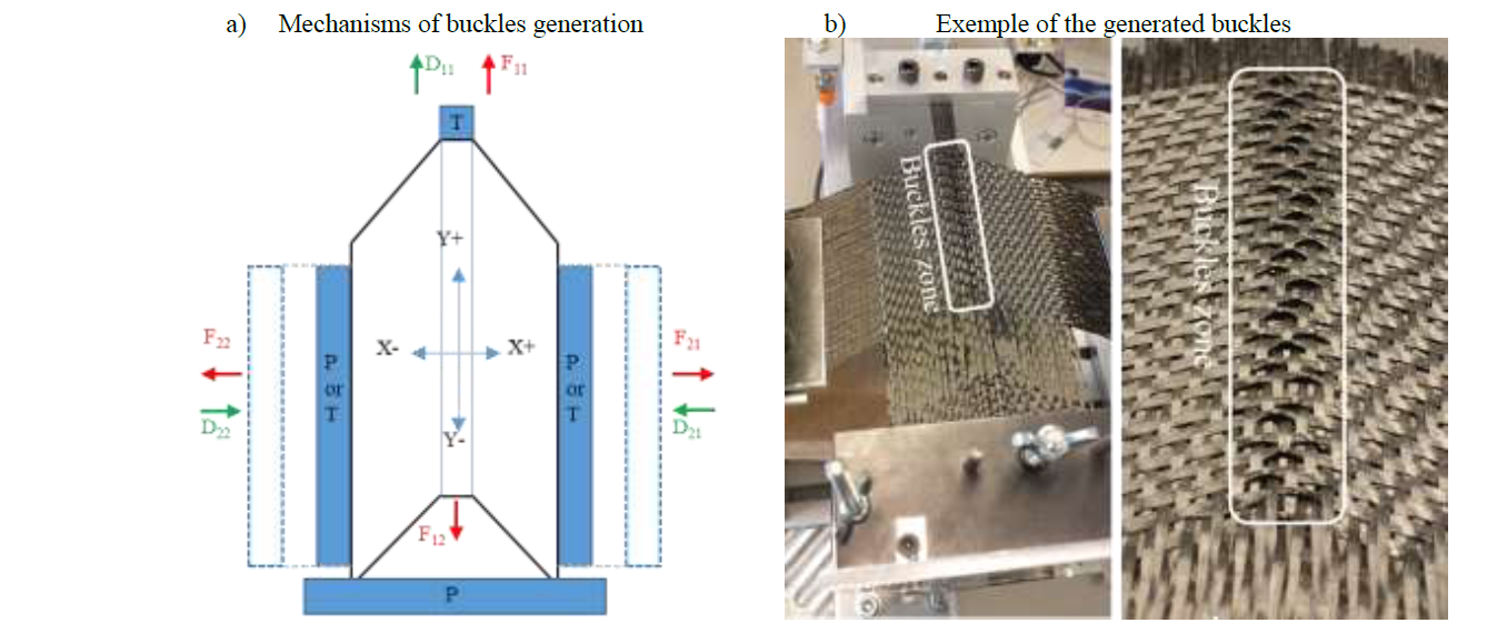
Fig. 5. Mechanisms of buckles generation
The Table 1 presents the characteristics of the generated buckles:
Table 1. Characteristics of the generated buckles with a tensile according to the warp direction.

Fig. 6 presents the tensile forces evolution as a function of the upper longitudinal axis displacement, during the experience.
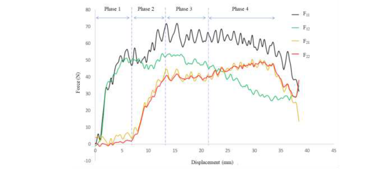
Fig. 6. Evolution of tensile forces during a test on G1151 fabric with a pressure of 0.08 bar- warp direction
The curves evolution can be divided into 4 phases, which represent the different mechanisms of buckle’s appearance. The first phase lasts until a displacement of 7mm. During this phase, the pulled yarns hold the whole fibrous network with them, due to the cohesion between the weft and the wrap yarns. Therefore, an in-plane bending of the transverse yarns takes place and induces a symmetrical shear at each side of the central part of the sample. This movement generates symmetrical resistant forces (F21 and F22) applied to the transverse sides. These forces are almost null in the first phase due to a decrease in the yarns crimp. The duration of the first phase varies depending on the initial pretension of the sample and/or on its positioning on the bench. This phase ends when the sample crimp is minimal. The second phase lasts from 7 mm to 13 mm and takes place when a lateral contact occurs between the weft and the warp yarns, leading to tensions F21 and F22, applied on the transverse yarns. These tensions increase significantly and symmetrically during this phase because they are generated by the sample's resistance to movement (static friction) which is caused by the pressure applied to the sample. The force F11 also increases from 50N to 70N. This increase represents the necessary contribution of F11 to initiate the movement of the fabric rotation and/or sliding, and therefore to overcome the static friction resistance between the reinforcement and the transverse jaws. Once the movement resistance is overcome, the third phase starts and lasts between 13mm and 22mm, as illustrated in Fig. 6. In this phase, dynamic friction occurs between the transverse jaws and the sample between them. Knowing that the forces applied by pressure are constant, we observe a pseudo plateau of evolution of all the forces. During this phase, the buckle defects are generated, as shown in Fig. 5,b. Furthermore, the curves show several decreases in peak values which could be due to differences in the local decohesion of the fibrous structure (Stick slip). This phenomenon might be amplified in this type of reinforcement (G1151) by the presence of a powdered resin which is not locally homogeneous. After an approximate displacement of 20mm, corresponding to the width of the fixing jaws, a loss of contact between the reinforcement and the jaws is observed, in the lower side of the sample as illustrated in Fig. 5,a. In this case, we consider the fourth phase four has started. The loss of contact starts with the central part of the sample, where the central yarns are pulled. The loss of contact increases until the sample is no longer held between the jaws. Hence, a decrease in the force F11 is observed because the resistance for movement is decreased. The curves exhibit a slight increase in the transverse forces (F21, F22) during this phase. This increase can be explained by the slippage occurring between the jaws and the ends of the sample. In fact, when the sliding starts, the contact surface tends to decrease with the swallowing of the reinforcement. Consequently, knowing that the normal force applied by the pressure is constant, the real pressure applied to the reinforcement increases, and consequently the transverse forces (F21, F22) also increase. The fourth phase is not relevant here because it does not occur during a preforming test, in which the reinforcement remains always under the blank holders.
After producing a sufficient number of fabric defected samples, they are stacked up inside a mold into which a liquid resin is injected to impregnate the samples. Next, the mold is removed and transferred into a preheated oven, set at 100 °C for 3 hours, in order to polymerize the resin. After removal of the mold from the oven, it is cooled down to the ambient temperature during 6 hours. Then, it is opened to remove the defected composite plate, as illustrated in Fig. 7.
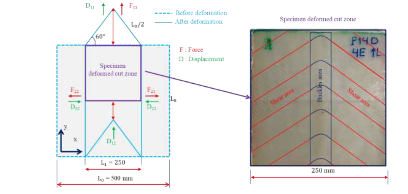
Fig. 7. Composite defected sample after deformation [9]
The manufactured composite plate is cut into several defected samples, in order to be tested in static and dynamic tests. The results of this part of the study were published in a previous research paper [9] and demonstrated that mesoscopic defects induce a significant effect on the mechanical behavior of the composite. They therefore need to be further investigated in order to avoid them, and this is the subject of ongoing studies.
5 Conclusion
This work has presented a new strategy to understand the mechanisms that generate mesoscopic defects during the forming of woven fabrics. This strategy is ensued through the design and implementation of an experimental machine to generate calibrated defects. The defects produced by this machine simulate the physical mechanisms involved during an LCM process preforming. Moreover, the machine makes it possible to change the values of several experimental parameters that have an influence on the types and amplitudes of defects, such as the number of the displaced yarns, the displacement strokes, the speed of displacement, the pressure applied on the fabric, the boundary conditions and the continuous control and adjustment of lateral pretension forces. The results have enabled us to define the experimental parameters values that correspond to the appearance of each type of defects and to provide additional information about the mechanisms and kinematics involved during the generation of these defects. The machine has also demonstrated the significant effect of the fabric cohesion in the avoidance of defects. Lastly, the machine can be used to carry out many studies for the manufacturing of composites samples with calibrated defects.
