1 Introduction
The introduction of polymer based composite materials in vehicle’s body in white is becoming more and more popular in the automotive industry. The automotive manufacturers are going this way in particular in order to reduce pollutant emissions of their vehicles and that results in the design and manufacturing of these so-called hybrid structures. In order to meet the CO2 emission target of 95 g/km in 2020 [1] it would be necessary to lighten vehicles by about 200 kg on average to comply with European upcoming regulations according to Nicolas and Echirpeau [2]. However, the manufacturing of such polymer-metal hybrid structures does not allow anymore the use of conventional joining technique such as resistance spot welding (RSW). Like it is the case for this study, the joining of a glass fibers reinforced polyester thermoset with a high strength steel cannot be achieved without an alternative joining technique.
Compared to other alternative joining techniques found in the literature including structural bonding (Huang et al., 2014), friction spot joining (FSpW) (Goushegir et al. [3]) and laser welding (Schricker et al., [4]), the self-piercing riveting (SPR) represents a better compromise and potential according to a comparative review reported in a previously related work (Amro and Kouadri-Henni [5]) and Settineri et al. [6]. Indeed, the SPR technique has strong advantages: not only matching with high volume vehicles manufacturing constraints and cycle time needs, it is both thermoset and thermoplastic compatible, doesn’t require any surface preparation and produces joint with higher static strength as well as good fatigue behavior.
Over the last ten years, a couple of studies have investigated the feasibility of polymer-metal joining with the SPR technique with various combination of materials. In an early study in 2009, Fratini and Ruisi [7] studied an assembly composed of a 1.5 mm thick aluminum with a 2.5 mm thick glass fiber reinforced thermoset for which a joint lap-shear strength of about 3 kN was measured. The authors mention that compared to metal/metal assembly, the rivet does not experience such plastic deformation in polymer/metal joining because of the composite layer which does not itself deform plastically. This phenomenon is more accentuated when the composite layer increases in thickness. Settineri et al. [6] investigated several combinations of aluminums and steels with various thermoset and thermoplastic polymers. In their work, emphasis is given to some of the SPR process parameters and their influence: it appears that a successful riveting operation is mostly dependent on the geometry of the rivet and an appropriate riveting force. The assembly of a 1 mm steel sheet with 3 mm SMC glass fiber reinforced thermoset produces a joint with 2 kN lap-shear strength. In another work, Gay et al. [8] showed a 2 mm thick thermoplastic PA6/6-GF50 assembled with a 2 mm aluminum exhibits a lap-shear strength of about 3.4 kN. It is concluded that the composite layer is the determining element driving the strength of the riveted joint. We do find in the literature studies where SPR process parameters were investigated like in Liu et al. [9] as well as rivet/die geometries in Mori et al. [10] for dissimilar metallic sheets assembly but there is still a lack of work done for polymer-metal association. In this study, the joining of a glass fiber reinforced thermoset SMC with a high strength low alloy steel HSLA380 is investigated. Besides verifying the feasibility of the joining with this material combination using self-piercing riveting technique and quantify mechanical strength, the principal aim of this work is to investigate experimentally, with the support of the numerical simulation tool, the damage and failure mechanisms of polymer-metal riveted joints under cross tension and lap-shear loads.
2 Mechanical tests procedure
In order to better understand and evaluate the mechanical strength of the riveted joints, as part of the investigation of the riveting parameters influence, two types of loading were studied: cross tension and lap-shear. To conduct the series of destructive tests, the riveted test specimens are made of rectangular sheets which size are 125 mm long and 30 mm wide. The rivet is positioned so that it is the center of a 38x38 mm² overlap square. The test configuration for both loadings are presented respectively in Figure 1a and 1b. Knowing the variability that can be associated with the composite material due to the random distribution of its microstructure and in order to get more representative results, three specimens for each configuration were used. Depending on the results, the specimens not consistent were discarded and the other values averaged to get a mean load for each configuration. The ultimate strength tests have been carried out using a single electro-mechanical 50 kN INSTRON traction machine allowing to switch clamping jaws to adapt from cross tension to lap-shear mode. For both loading type, a constant loading speed is set to 5 mm/min until the failure of the specimens is reached where the test is stopped. Each of the riveting process parameter testing is performed independently from the other. Materials mechanical properties of steel layer HSLA380 and SMC reinforced thermoset are mentioned in Table 1.

Table 1. Mechanical properties of the materials involved.
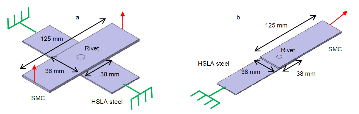
Fig. 1. Traction testing machine for both cross tension mode. (a) cross tension mode and (b) lap-shear mode
3 Numerical tool modelling and validation
The 3D FE model is based on the deformed geometry resulting from the 2D axisymmetric simulation after what a revolution is performed around the axis of symmetry. The materials modelling approach and meshing strategy, using in particular mixed FE formulation arbitrary Lagrangian-Eulerian (ALE), have been more detailed in a previous related work (Amro and Kouadri-Henni [5]). The spatial discretization, presented in Figure 2, was carried out to satisfy several needs. First, optimize the size of the model so as to minimize the computation time and focus the mesh refinements to the areas of interest. In addition, as the two types of loads, i.e. cross tension and lap-shear, to simulate can be considered as symmetrical, it was not necessary to model the entire geometry but only one half. Then, faithfully reproduce the experimental conditions under which the experimental tests are carried on. Finally, to allow to simulate the two types of load studied with a single model. The mesh refinement zones located around of the rivet are necessary to guarantee a good-quality mesh in these areas identified with curvatures and complex features. The 3D mesh is composed in total of 73 342 elements, 44 835 of tetrahedron type and 28 507 of hexahedron type.
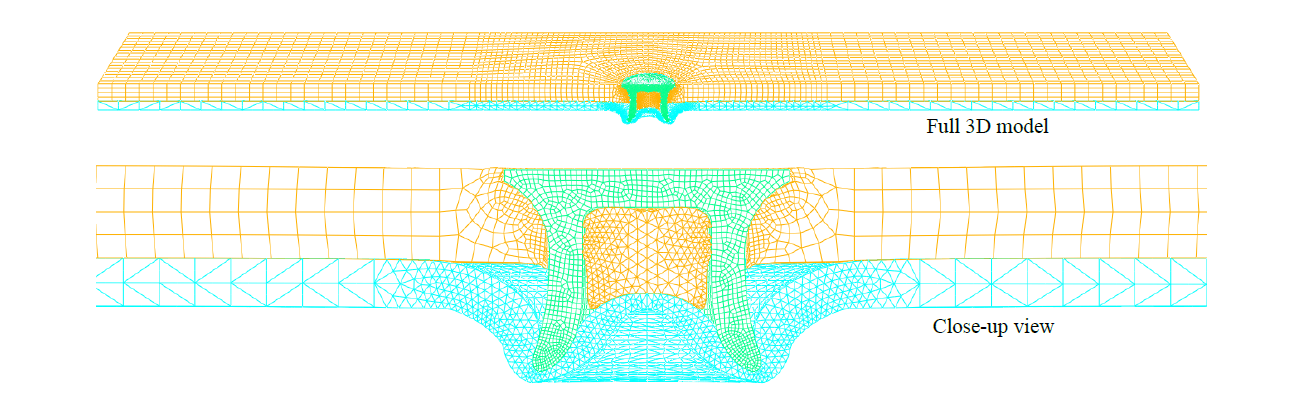
Fig. 2. Spatial discretization of the 3D FE model using Abaqus 6.13-1.
The Figure 3 shows the comparison of a riveted joint final cross-section predicted by the simulation and an experimental test performed in the same operating conditions. At first glance, we can see an overall good correlation between experimental data and simulation prediction. The interlocking u is well predicted as the simulation ends up with 0.182 mm which is very close to the 0.173 mm measured on average over three specimens and for both sides of the cut. However, the simulation predicts a minimal thickness tmin of 0.254 mm significantly lower than the experimental measurement of 0.452 mm. Regarding the minimal thickness at the joint center tmin center, the simulation prediction of 0.369 mm overestimates the experiment with 0.260 mm despite the important dispersion for this measurement.
In the process of experimental validation of the SPR FE 2D model, one can look at the riveting cycle as shown in Figure 4 for both simulation and experiment. There, one can see the evolution of the riveting force during the entire travel of the rivet. We can point out first the good overall agreement between simulation and experimental responses. During the first phase of the process where the rivet is going through the first composite layer, the simulation prediction is close while underestimating. Then in the next phase which starts when the rivet has completely gone through the composite layer and starts to push on the steel layer, approx. at 3.5 mm travel, one can spot a more significant overestimation of the force calculated. As this phase ends, approx. at 1.5 mm, the simulation prediction tends to get closer to the experimental measure. Finally, in the last phase where the rivet starts to bend and deform the steel layer along the profile of the die, we see again a good correlation between simulation and experiment data despite an underestimating response from the calculation.
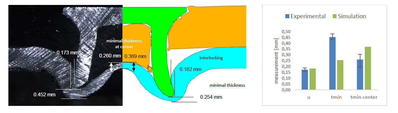
Fig. 3. Comparison of a riveted joint cross-section profile: experimental (left) and SPR 2D simulation (right).
Starting with Figure 3, we can point out a couple of reasons causing the lack of a better prediction from the simulation. We can particularly mention the failure criterion adopted for the top composite layer based on element deletion causing the loss of material in such a way that is seems to have a significant influence on the penetration of the rivet which is in fact facing less resistance during its travel. As well, this loss of material causes the central part of the steel layer to undergo less pressure from the above composite cut part pushed down by the rivet. That might explain why the simulation overestimates the thickness of the steel sheet at the center (tmin center).
The overestimation of the load spotted in the intermediate phase of the riveting cycle (Figure 4) can be explained by the fact that the simulation, where the riveting machine elements (punch, sheet holder and die) are considered rigid bodies, does not take into account the existing rigidity of the riveting machine, which is in reality not infinite. As a result, the deformable parts in the simulation are eventually subjected to higher loads than it would be in experimental conditions. Also, we know that the maximum flexibility of the riveting machine is reached when the rivet pushes on the steel layer, the stiffest of the layers, which corresponds to where the lack of correlation is the highest. These differences in the results due to modelling choices have also been encountered in other studies such as the one of Ma et al. [11] where the simulation had greater stiffness.
We could also bring this effect of greater stiffness in the simulation closer to the discussion of the riveted cross-section comparison above. In fact, a greater load applied by the rivet in the simulation to the steel layer could be an additional reason to the minimal thickness tmin being that much underestimated.
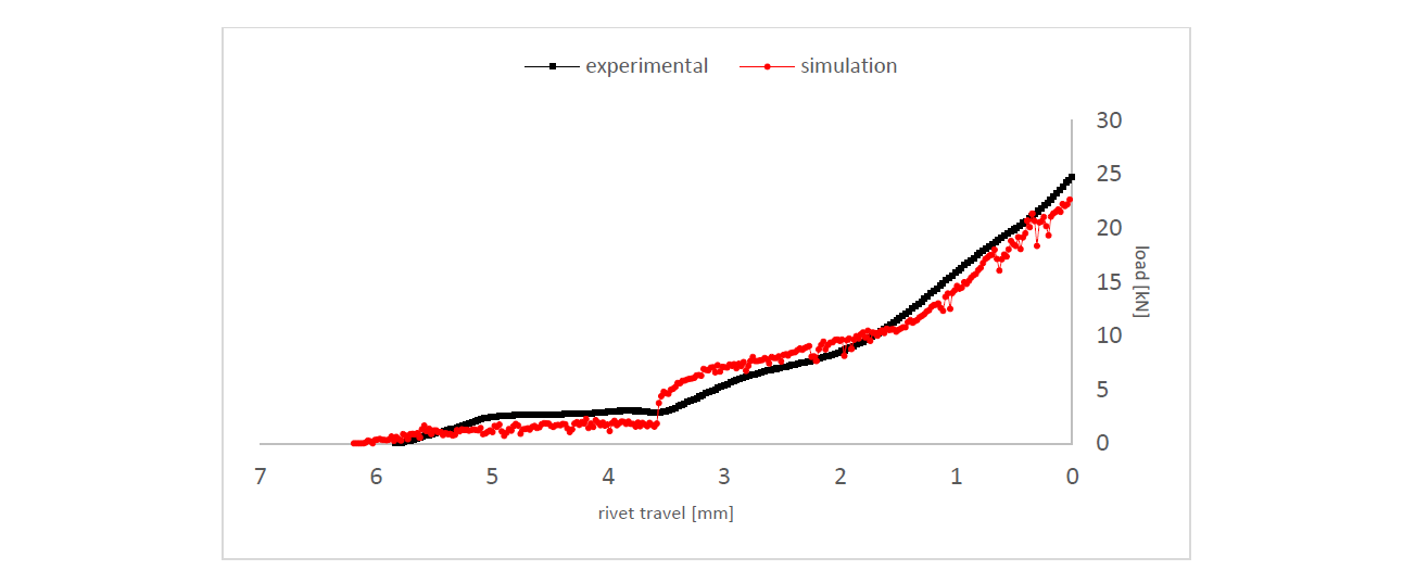
Fig. 4. Riveting cycle (velocity = 100 mm/s): comparison between simulation prediction and experimental measure.
4 Composite layer damage during SPR process
During the riveting operation, the composite layer positioned in the upper layer is traversed over its entire thickness which locally damages the material around the rivet trajectory. The influence of the riveting process on the damage has been studied on a macroscopic scale with the riveting velocity as variable because it is known that it can have a influence on the damage of the polymer-based material as reported in Dhakal et al. [12]. A preliminary observation made on the specimens did not report recognizable cracks on the surface, hence the focus was on measuring the outer diameter of the aperture produced by the penetration of the rivet through the composite layer. This measurement was therefore made for different riveting velocities ranging from 20 mm/s to 100 mm/s and considering a 20 mm/s interval.
The evolution of the composite layer aperture outer diameter with riveting velocity as variable is shown in Figure 5 as well as the cross-section of riveted joints, focusing on the area of interest, which are shown for each of the tested riveting velocity. Since three specimens are available for each configurations, the retained measurement is the average of each single measurement. We can see on the figure that as the riveting velocity is increased, the aperture outer diameter increases as well with a clear trend despite an important spread for some of the measurements, i.e. 80 mm/s and 100 mm/s in particular. Though, the increase remains relatively small as we notice an evolution in diameter from 6.5 mm in configuration 20 mm/s to 7.22 mm in configuration 100 mm/s which represents 0.72 mm more (+11.1%). We can notice as well that the aperture diameter does not deviate much from the diameter of the rivet head, i.e. 6 mm, which is the last feature of the rivet after its cylindrical part to penetrate the composite layer.
The measured rise in aperture diameter suggests that the composite material is sensitive to the evolution in riveting velocity. In fact, a higher impact velocity means a higher energy to absorb by the composite layer: here with a 100 mm/s, 5 times the lowest velocity tested, the energy to withstand is multiplied by a factor of 25. It has to be mentioned that the numerical simulation tool was not sensitive enough to be able to reproduce significantly the effects, which have been observed experimentally, due to varying the riveting velocity.
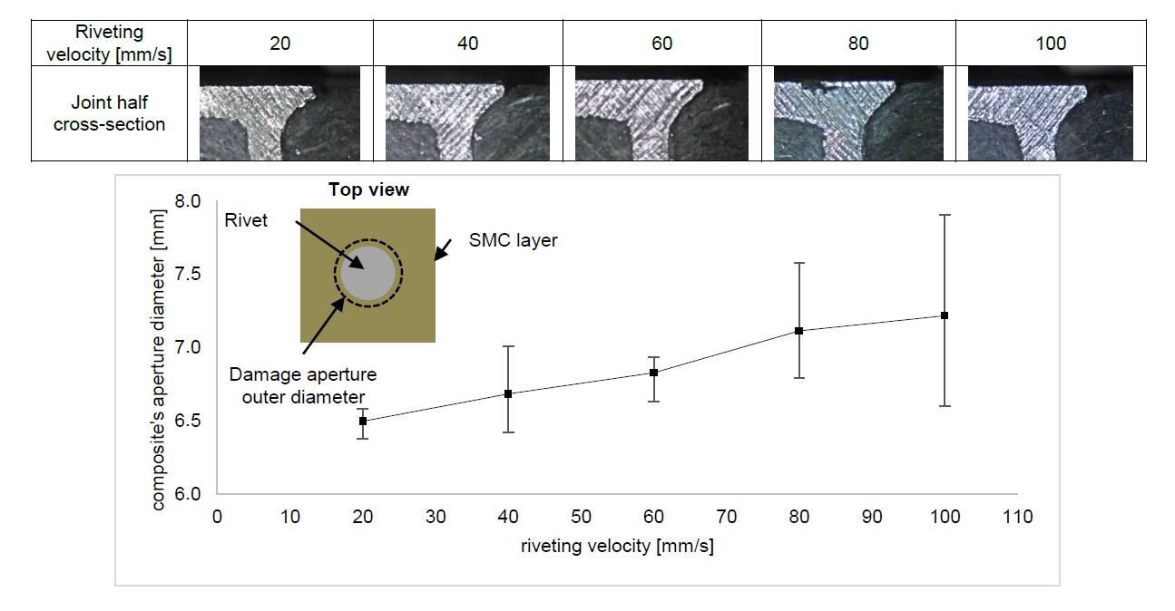
Fig. 5. Evolution of aperture diameter in the composite layer with change in riveting velocity.
5 Failure mechanisms of riveted polymer-metal joint
The Figure 6 shows the typical riveted joint profile at failure for both loading conditions, cross tension (6a and b) and lap-shear (6c and d). Even if the joint fracture mode is the same for both loading conditions, it appears that the type of composite layer failure differs.
In the case of cross tension loading, we can see that the pressure applied by the rivet head has forced the original aperture to extend up to the point where the rivet head has completely gone through the composite layer thickness. The joint failure mode is very characteristic of a tearing of the upper layer. During progressive loading, the pressure exerted on the sides of the orifice via the rivet head increases and forces it to enlarge. In this mode of rupture, the detachment of the composite is done without tearing of material. There, the composite failure is recognizable with the emerging of multiple macroscopic cracks (6b) which propagate from the aperture’s edge to the rest of the part in orthogonal directions which highlight this phenomenon. The numerical prediction manages well in reproducing the experimental deformation apart from the cracks which cannot be reproduced by considering the management of the rupture of the composite in the digital model.
In the case of the lap-shear tension, once the pressure applied by the rivet cannot be sustained by the composite layer, the rivet head eventually penetrates the composite material in the thickness while pulling out some materiel in the same time. The failure mode is akin to delamination of the upper layer by compression. In this failure mode, the composite substrate, which offers a much lower resistance than the other elements of the joint, lets the head of the rivet driven in the opposite direction penetrate its thickness through so that the latter eventually disintegrates more from the starting aperture and gradually let the rivet sink inwards. We can see on the experimental deformation that part of the rivet is no longer visible. For this purpose, the numerical prediction does not match very well in reproducing the experimental deformation. It is noted during loading that the composite, instead of disintegrating, produces sufficient strength to produce a leverage on the rivet and cause its partial loosening. Once in this position, the rivet no longer fully performs its mechanical function and causes a sudden drop in the joint resistance. This side effect could be fixed by taking into account the residual stresses that the rivet is subjected to after SPR operation release.
It has to be specified that for the entire tensile tests conducted in this study, the joint fracture mode was identical, i.e. the composite layer failure. This observation is commonly reported in the literature, Settineri et al. [6] and Gay et al. [8] , for this kind of materials arrangement. In fact, this phenomenon can be expected when considering the mechanical properties of the composite are globally much lower in comparison with the steel layer and rivet.
The feasibility of the joining has eventually been verified for the material combination chosen for this study, i.e. GF thermoset / HSLA380 steel. It has been found out that, under the best set of riveting parameters, the joint is sustaining a maximum load of 1.68 kN and 1.92 kN for respectively cross tension and lap-shear tension modes. The lap-shear strength measure is in accordance with literature figures and more particularly with the work of Settineri et al. [6] where a similar material combination has been studied.
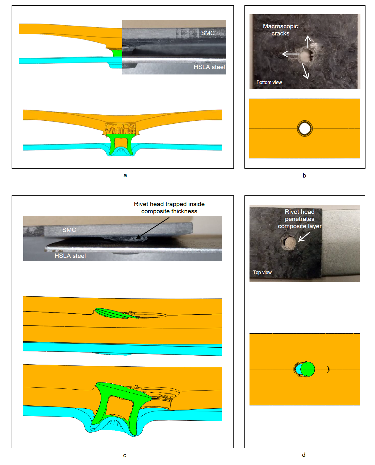
Fig. 6. Typical fracture mode and profile. Experimental observations associated with numerical tool predictions. (a, b) cross tension and (c, d) lap-shear tension
6 Conclusions and recommendations
In this study, the mechanical behaviour of polymer-metal joints joined by self-piercing riveting technique has been investigated. This problematic is part of a larger challenge faced actually by the automotive industry which is massively engaged in the reduction of the mass of their vehicles, through the introduction of composite-made materials in particular, intending ultimately to reduce carbone footprint of their products.
In an effort to assess mechanical behaviour of a reinforced polymer- steel joints assembled by SPR process, experimental testing were conducted by means of cross tension and lap-shear tests. In parallel a numerical model was developed in order to provide complementary understanding of the material behaviour throughout SPR process operation and during the destructive testing.
Applied to a glass-fiber reinforced thermoset / high strength steel HSLA380 assembly (respectively 2.5 mm and 1.3 mm thickness), the feasibility of the joining has been verified and joint exhibits 1.68 kN in cross tension strength and 1.92 kN lap-shear tension strength.
Regarding the composite layer, the results showed that the material is sensitive to the evolution in riveting velocity but to a limited extent and the diameter of the aperture does not deviate much from the diameter of the rivet head.
Although the polymer-steel riveted joints testing concluded that the composite layer is the failing element every time, the failure mechanisms were found to be different depending on the loading conditions. Cross tension loading leads to tearing of the composite material highlighted by multiple macroscopic cracks. Lap-shear tension loading on the other hand leads to delamination as the compression load applied by the rivet cannot be sustained by the composite layer. Experimental observations could be predicted overall with numerical predictions.
In order to deeper in the analysis of damage and fracture mechanisms of the composite material at a microscopic level, it is planned to use SEM analyses. Another recommendation would be to enhance the numerical tool meshing strategy so it can be sensitive to the variation in riveting velocity.
Acknowledgements
The authors acknowledge the National Institute for Applied Science of Rennes, France for supporting this work. The authors would like also to acknowledge manufacturers PSA (factory of Rennes, France) and Faurecia for their technical support and for providing the raw materials to conduct experimental testing.
