1 Introduction
Clinching is a common joining process in lightweight design. It is conducted without any auxiliary parts and only through localized cold-forming of the joining parts. The clinch point’s quality is usually assessed by measuring characteristic dimensions such as bottom thickness, neck thickness and undercut in a microsection (cf. Fig. 1). However, this ex-situ method is conducted after clinching and, therefore, is unable to detect phenomena immediately during the joining process. For instance, elastic deformations reverse and cracks partly close after unloading. Methods, which investigate the joining parts during clinching (in-situ), such as the force-displacement evaluation are used to control a clinching process online, though deviations in the clinch point geometry cannot be specified with this method. Apart from that, modelling damage and failure of mechanical joints requires a deeper understanding of damage initiation and damage growth, which cannot be gained with conventional measuring methods. Consequently, new methods are necessary to analyse the process and the geometry of the joining parts in-situ.
CT scanning uses multiple X-ray images of an object from several angels to reconstruct a three-dimensional image of the object in high resolution. Therefore, it is a widely used method for geometry analysis [1]. Above that, damage phenomena in joining zones, such as drilled holes [2] or riveted components made of fibre-reinforced plastics (FRP) and aluminium (Al) [3], are characterized. Using CT for in-situ measurements can eliminate some drawbacks of ex-situ methods. Füßel et al. investigated damage phenomena in adhesively bonded riveted single lap joints of FRP and Al during shear testing in in-situ CT [4]. As a result, the damage initiation in the adhesive layer and the chronology of the subsequent failure could be described. Furthermore, in [5] in-situ CT analyses of the deformation and damage of metal inserts in FRP were conducted. Here, the detachment of the boundary FRP layer and the insert, fibre fracture and delamination was shown.
To overcome the limitations of current analysing methods for clinch points, the clinching process can be investigated using in-situ computed tomography (in-situ CT) in a test set-up as shown in Fig. 1 (a) and (b). Here, X-rays emitted by the tube penetrate the clinching tool and a specimen, consisting of two 2 mm thick Al EN AW 6014 sheets, and then are collected at the detector. This method involves several challenges. Firstly, using a common clinching tool made of steel would cause an overall low scan quality and strong artefacts in the CT measurement. Secondly, the interface between the joining partners (sheet-sheet interface, cf. Fig. 2 – red line) is hardly detectable due to the high local compression. However, the sheet-sheet interface is especially important for measuring the undercut and the bottom thicknesses of each sheet. Both issues reduce the usability of this method significantly.
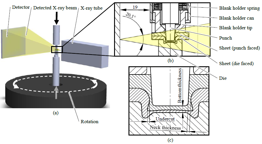
Fig. 1: Schematic test set-up in the in-situ CT (a), the reference clinching tool and process set-up (flipped vertically) (b) and the characteristic dimensions of a clinch point (c) (based on [6]).
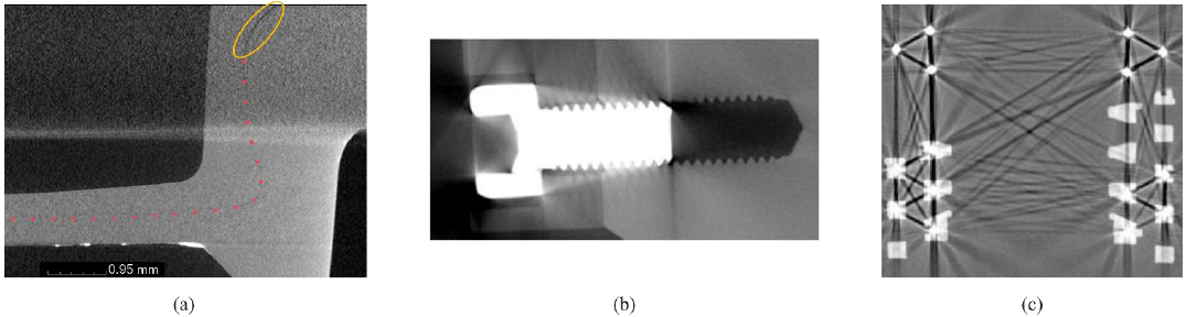 Fig. 2: Exemplary CT-image of a clinch point (a) with a poorly visible sheet-sheet interface (red dotted line). The gaps in the bulging area are marked with yellow circles. Artefact examples: A CT-scanned screw with scatter artefacts (b) and metallic wires in a plastic connector creating metal artefacts (c) [7].
The overall scan quality is mainly driven by the image contrast and resolution. The former is influenced by the X-ray intensity reaching the detector [7]. The latter is achieved by a small focal spot [7]. The detected intensity depends on the initial intensity emitted by the tube and the interaction with the object (attenuation). The X-ray tube’s power influences both the initial intensity and the focal spot size [7]. Consequently, keeping the attenuation caused by the object at a low level, merely a low tube power is necessary to penetrate the object and a small focal spot is achieved. Since parts of the tool components are penetrated by the X-ray beam (cf. Fig. 1), a good image quality is only achieved with a low attenuation caused by the tool. The attenuation is a result of four effects: the photoelectric effect, Compton scattering, Rayleigh scattering and pair production [7]. In [6] it is shown that for this in-situ set-up the attenuation coefficient 𝜇 is primarily affected by the photoelectric effect. Furthermore, the attenuation coefficient by the photoelectric effect 𝜇𝑃𝑒 is proportional to the fourth power of the penetrated materials atomic number [8]. Compton scattering is a minor effect additionally increasing the attenuation coefficient and it is proportional to the photon energy and to the mass density [9]. Consequently, for this set-up materials with primarily low atomic number and secondly low density can be considered as radiolucent. Vice versa, the opposite is valid for radiopaque materials.
Additionally to the overall scan quality, the CT measurement is affected by artefacts, which are false scanning phenomena that usually have multiple causes. Well known are metal artefacts in medical CT scanning as they lead to dark stripes between metal parts and pin-striped streaks in the non-metal parts (cf. Fig. 2 c) [7]. One of the causes is the high attenuation of the metal parts compared to its surrounding volume [7]. Scatter artefacts can be recognized as streaks at locations with sharp scatter fluctuation such as sharp edges in multi-material objects (cf. Fig. 2 b) [7]. Scatter radiation is caused by X-rays which are absorbed and then re-emitted with a different angle [7].
In [6], tool materials, that are predicted to be CT-suitable, are numerically investigated on their mechanical performance during clinching. As a result, ceramics such as silicon nitride and titanium carbide and titanium alloys are found to be mechanically suitable for the punch and the die. Furthermore, materials of lower strength such as carbon fibre reinforced PA66 are suggested for the blank holder. To verify the theoretical findings, this work investigates experimentally tool materials that allow artefact-reduced high-resolution CT measurements during clinching. Furthermore, radiopaque materials that can be applied between the joining parts to enhance the detectability of the sheet-sheet interface are investigated.
2 Materials and Methods
2.1 Clinching Tool Material
Based on the selection in [6], silicon nitride, titanium alloy grade 5 and aluminium (Al) EN AW 7075 are investigated as clinching tool material. Relevant material properties are shown in Table 1. Since alloys are compounds of different materials, an effective atomic number (EAN) is calculated with the weight fractions of their basic elements. The same is done for ceramics with the molecular fraction.
Table 1: Investigated radiolucent tool materials and a tool steel (for comparison) and their mechanical and CT relevant properties.
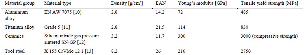
To estimate the CT-suitability of the investigated materials, the attenuation coefficient is used. The materials’ attenuation coefficients μ can be calculated using the mass attenuation coefficients μ/ρ from [14] and the materials’ density. For compounds an effective mass attenuation coefficients is calculated using the molecular fraction for molecules respectively the weight fraction for alloys.
For the test set-up, a transmission tube with a carbon diamond filter of 0.35 mm and an aluminium filter of 0.3 mm thickness is used. The applied scanning parameters are shown in Table 2. The energy spectrum for this configuration can be simulated with aRTist 2.0 [15,16] and a mean photon energy emitted by the tube of 53 keV can be determined. The effective attenuation coefficients of the investigated tool materials, as well as the X-ray energy spectrum are shown in Fig. 3. Thus, the best scan quality can be expected from aluminium and silicon nitride. Titanium is expected to lead to a lower image quality, even though it is estimated to be a lot better than tool steel.
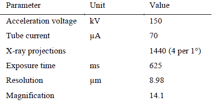
Table 2: CT-parameter of the CT-system FCTS 160 – IS from FineTec FineFocus Technologies GmbH
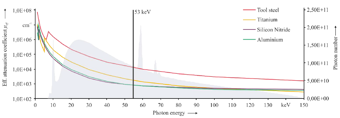
Fig. 3 Effective attenuation coefficients of the investigated tool materials and of tool steel (for comparison) over the photon energy. The energy spectrum (grey background) and its mean energy (vertical black line) of the X-rays emitted by the tube.
In order to assess the CT-suitability of materials, an experimental set-up with a clinch tool mock-up is chosen. The mock-up is a simplified cost-efficient version of the actual clinching tool (cf. Fig. 4). Additionally, only these components are introduced, which are penetrated by the X-ray beam.
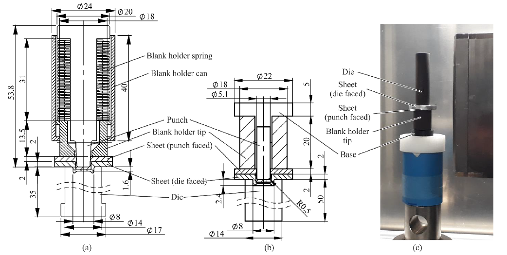 Fig. 4: Technical drawings of the real clinching tool (a) and the simplified mock-up (b). As only the lower traverse of the testing machine in the real CT set-up is movable (c), the die and the punch are flipped vertically.
2.2 Radiopaque Material
To enhance the detectability of the sheet-sheet interface, radiopaque materials can be applied between the joining parts. Thus, materials in form of thin foils and solutions with dissolved radiopaque material are investigated. A foil is advantageous because of the accurate dosing and an even distribution. On the other side, solutions with dissolved radiopaque material can be applied for coating and infiltrates any pores in the sheets surface using the capillary effect. Both, foil and powder need to have a high EAN and a high density in order to visualize the sheet-sheet interface (cf. section 1). Furthermore, a high elongation at break is necessary for the foil in order to withstand the high deformations during the process. Additionally, the Young’s modulus and the strength is supposed to be low so that the sheet deformation is influenced to a low degree only. The soluble material, on the other hand, needs to have a high solubility in water in order to accumulate a sufficient amount of radiopaque coating on the surface. Table 3 shows the investigated soluble materials which are available in powder form. The table is dominated by iodides because iodine is an element with a high atomic number. The investigated foils are described in Table 4. Tin and lead are chosen as they exhibit a high atomic number, a very high elongation at break and a low stiffness. The effective attenuation coefficients of the investigated radiopaque materials, as well as the X-ray energy spectrum are shown in Fig. 5. While all iodides and foils show a generally high attenuation at the mean photon energy, the highest attenuation can be expected from lead, tin and barium iodide.
Table 3: Investigated solutions for radiopaque layer. 2.5 ml isopropanol and 2.5 ml COMPARD WAC Wetting Agent are added to each solution.
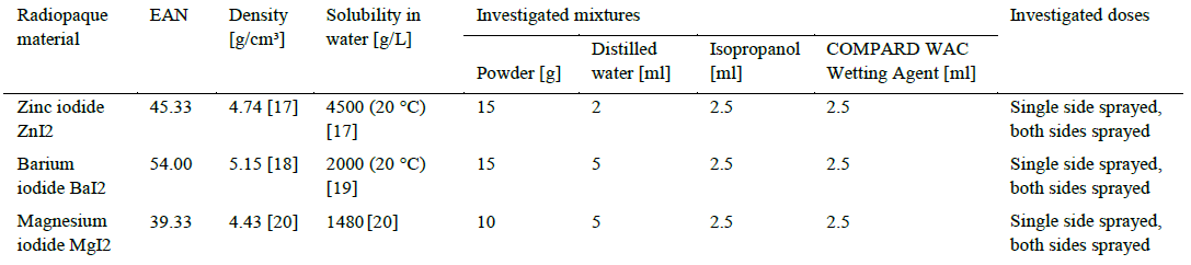
Table 4: Investigated foils for radiopaque layer [21]
![Table 4: Investigated foils for radiopaque layer [21]](docannexe/image/2781/img-8.png)
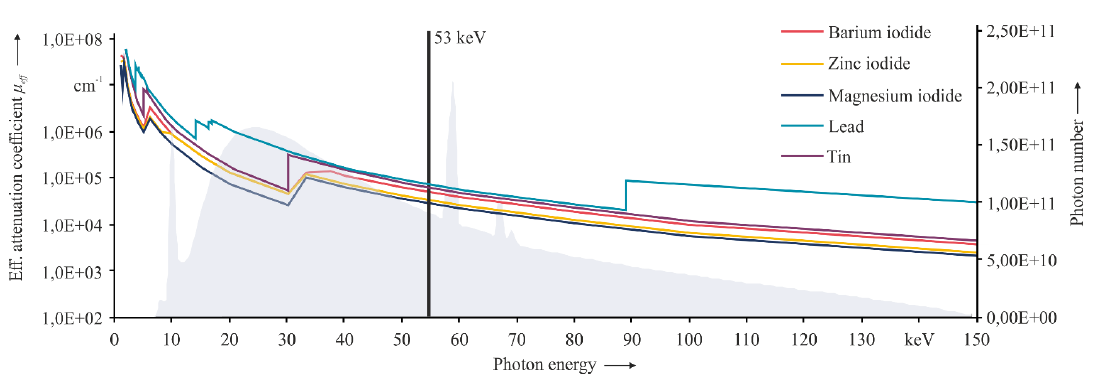 Fig. 5: Effective attenuation coefficients of the investigated radiopaque materials over the photon energy. The energy spectrum (grey background) and its mean energy (black vertical line) of the X-rays emitted by the tube.
Initial tests with 50 and 100 μm thick foils showed a strong attenuation at the foil decreasing the scan quality. Consequently, 10 μm thick foils are used. The sheets are die cut into discs of 8 mm diameter and the centred positioning on the aluminium sheet is supported by markings on the sheet according to Fig. 6 (a and b). The investigated soluble materials are mixed with distilled water according to Table 3 to achieve the highest possible concentration. Each solution is additionally mixed with isopropanol to support evaporation. Additionally COMPARD WAC Wetting Agent is added to decrease the surface tension for a better surface wetting. Initial tests with the solution applied to only one sheet showed no sufficient attenuation in the CT-scan. Thus, both aluminium sheets are treated twice on the interface side with an evaporation time of 48 hours in between. Fig. 6 shows exemplary the aluminium sheet with the zinc iodide solution 48 hours after the first application (c) and shortly after the second application (d). The specimens are clinched 24 hours after the second application with a clinching force of 31 kN with the 739000B Punch (D = Ø 5.5 mm) and the 739100F die from the 940 series from BTM (Europe) Blechverbindungstechnik GmbH.
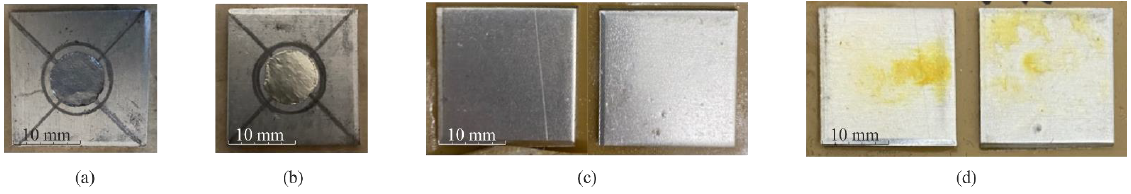 Fig. 6: Positioning of the 10 μm lead foil (a) and the 10 μm tin foil (b). Wetting of the aluminium sheets with radiopaque solutions 48 hours after the first application (c) and directly after the second application (d).
3 Results
3.1 Tool Material
The CT-scans are evaluated qualitatively and using their grey value histogram. Generally, all investigated tool materials lead to a scanning result with few streak artefacts (cf. Fig. 7, red circles). Both the aluminium (a) and the silicon nitride (b) tool qualitatively show a similar good result, while the titanium tool (c) dims the specimen in such a way that the detectability of the exemplary sheet-sheet interface in the bulging area is decreased (yellow circles). In order to increase contrast, a higher X-ray tube power would be necessary, which also leads to an enlargement of the focal spot coming along with a declined resolution. Considering the grey value histogram, it can be stated that only the titanium tool allows a clear distinction between tool and specimen (blue arrow). For the silicon nitride tool a slight hump is noticeable in the histogram (blue arrow), which represents the aluminium specimen.

Fig. 7: CT-results and the grey value histograms of the aluminium (a), silicon nitride (b) and titanium tool (c) set-up. The streak artefacts are marked with red circles, the partly visible sheet-sheet interface is marked with yellow circles (images are flipped vertically). The high peak in the first hump of the grey values represents the attenuation by air (green arrow), the slight hump at the silicon nitride histogram represents the aluminium specimen (purple arrow) and the minimum at the titanium tool indicates the good contrast between tool and specimen (blue arrow).
3.2 Radiopaque Material
The scanning of the specimens with dissolved radiopaque material reveals that they are slightly visible in the sheet-sheet interface but they are distributed very irregularly (cf. Fig. 8 a, yellow circle). Additionally, radiopaque material accumulates in the bulging area (cf. Fig. 8 c, red circle). Only barium iodide visualizes an almost consistent sheet-sheet interface (cf. Fig. 8 b). The radiopaque foils exhibit an increased attenuation marking the sheet-sheet interface (cf. Fig. 9). However, for the lead foil this is accompanied by more emphasized streak artefacts and blurring (cf. Fig. 9 a, red circles). The tin foil exhibits significantly less pronounced artefacts (cf. Fig. 9 b red circle), but a wrinkling of the foil occurs in the bulging area (cf. Fig. 9 b, yellow circles).
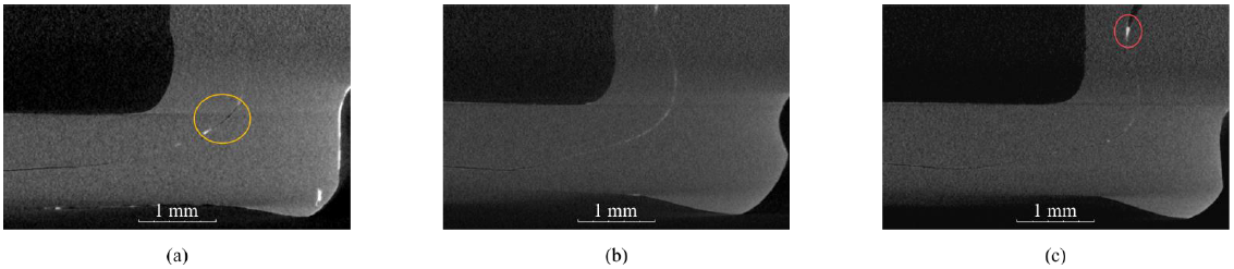 Fig. 8: CT-results with ZnI2 (a), BaI2 (b) and MgI2 (c) solution. The accumulation of radiopaque material is marked with a red circle and the inconsistent coating is marked with a yellow circle (images are flipped vertically).
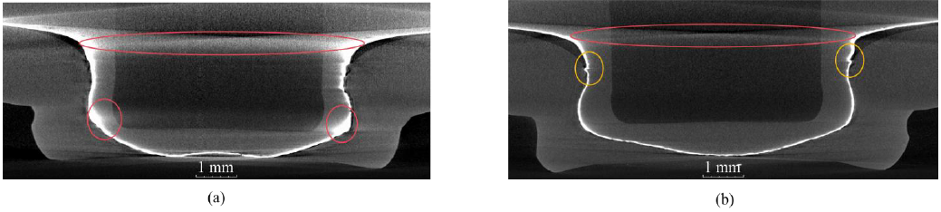 Fig. 9: CT-results with lead foil (a) and tin foil (b). The streak artefacts and blurring are marked with red circles and the wrinkling is marked with yellow circles (images are flipped vertically).
4 Summary, Conclusions and Outlook
The clinch point’s quality is usually assessed by measuring characteristic dimensions, which, however, do not yield the detection of phenomena occurring during the joining process. In order to overcome these drawbacks, the clinching process can be examined using in-situ CT. This poses some challenges. Firstly, using a clinching tool made of steel would cause an overall low scan quality and strong artefacts. Secondly, the sheet-sheet interface is hardly detectable in the remaining clinch point due to the high compression, which reduces the ability to measure the clinch point’s characteristic dimensions. Thus, firstly alternative tool materials are experimentally analysed that allow artefact-reduced CT measurements. For this purpose, mock-ups of the original clinching tool made of different CT-suitable materials are examined in CT. Secondly, radiopaque materials are experimentally investigated that allow an enhanced visibility of the sheet-sheet interface. Here, radiopaque layers in form of thin foils and solutions with dissolved radiopaque material are applied between the sheets before clinching and the sheet-sheet interface is examined in CT.
Generally, it can be concluded that all investigated tool materials would allow the analysis of the geometry and of phenomena such as fractures in an in-situ CT of a clinching process. While the titanium tool exhibits a high contrast to the specimen, the dimming of the specimen decreases the detectability of small-scale phenomena like cracks and pores. However, using materials, such as aluminium and silicon nitride, of similar attenuation as the specimen’s material could hinder the detectability of the sheet-tool interface considering the high compression in the in-situ test set-up. To compensate for that a coating of the tool might be necessary.
Among the radiopaque solutions, only the barium iodide can sufficiently mark the sheet-sheet interface. Even though the layer is quite thin and the sheet-sheet interface is only weakly visible, characteristic dimensions of the clinch point can be measured. Only the application of the tin foil lead to a good quality of the CT image. Nevertheless, given the good visibility of the interface, it shall be investigated whether a thinner foil can be sufficient in future work. Introducing a layer between the sheets to be clinched alters their frictional behaviour. Consequently, the extent of influence needs to be investigated in future work.
Acknowledgements
This research was funded by the German Research Foundation (DFG) within the project Transregional Collaborative Research Centre 285 (TRR 285) (project number 418701707), sub-project C04 (project number 426959879).
