1 Introduction
The reinforcement of concrete with rebars enables substantial increase of design freedom, resource-efficiency and safety. As can be seen in the example of Fig. 1 thin-walled and elegant buildings can be realized by reinforced shell constructions. Regarding design of such structures, secondary forming of the reinforcing elements is a widely used method to provide the required stirrups, angles or individually curved segments. Forming operations are comparatively simple to realize if conventional isotropic metallic materials are used. On the other hand, these involve the risk of corrosion and consequently a need for frequent inspections or restauration.
In order to overcome these problems and to enhance the lightweight potential of future buildings, novel reinforcing materials are being developed. In this context, rebars made of fiber-reinforced polymers (FRP) allow substantial improvement along the whole life-cycle [1]. To meet high requirements in terms of heat-resistance and mechanical properties, especially thermoset matrix materials are of interest. As thermosets form a molecular network during manufacturing, they are often classified as non-formable. In contrast, thermoplastic matrix materials can be repeatedly molten and re-shaped at elevated temperatures in order to generate global or local functionalities [2]. Hence, curved thermoset FRP rebars are currently manufactured by using individual molding tools or adapted technologies like radius pultrusion resulting in fixed curvatures and radii [3]. Hence, only straight profiles or readily formed rebars with pre-defined shape are commercially available [4]. However, in dependence on composition and temperature [5,6] thermosets may allow a notable degree of plasticity, which is often neglected or unknown. A distinctive brittle-ductile transition can be observed in the vicinity of glass transition temperature [7–9]. Under this premise, it is suggested to makes use of the plastic deformation potential of thermoset matrix materials in order to gain a substantial increase in flexibility, cost-efficiency and lightweight potential of future FRP reinforced concrete structures.
An experimental program was performed using a commercially available fast-curing epoxy resin system. A reaction kinetic model is calibrated according to DSC data and subsequently employed to define adapted cure cycles that result in partial cure states. Quasi-static tests in tensile and compression mode were conducted at elevated temperatures using partially cured neat resin specimens. General guidelines for forming are derived and transferred to bending experiments on carbon fiber-reinforced polymer (CFRP) specimens that were manufactured from the same epoxy resin. Instead of pultruded rebars, composite stripes were cut from molded plate material in order to rely on a simplified manufacturing method that enables a trouble-free variation of fiber orientations, fiber volume content and degree of cure.

Fig. 1. “Kurmuschel” in Sassnitz (Germany) based on a shell construction with conventional steel rebars (picture by J.-H. Janßen, CC BY-SA 4.0)
2 Materials and Methods
2.1 Material Selection and Pre-Cure
Commercially available resin XB6469 resin and Aradur 2954 hardener supplied by Huntsman International LLC were selected. The components are mixed to a ratio of 100:42 pbw and degassed prior to testing and manufacturing. Neat resin was used for DSC scans in order to generate input data for reaction kinetic modelling. Partially cured resin material was used to determine the dependence of the glass transition on degree of cure (DOC).
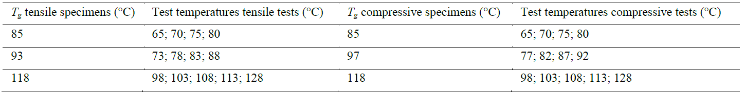
Furthermore, solid but partially cured neat resin specimens were used for quasi-static testing. Tensile test specimens were partially pre-cured in a RTM molding tool at 60 °C for 6 h. Compressive test specimens were cured in glass cylinders that were sealed on the bottom side with Tacky Tape and placed in a convection oven at a similar cure cycle. After cutting the tensile and the compressive specimens to the required dimensions, they were post-cured in convection oven at the temperatures and dwell times given in Table 1. The resulting graded glass transition temperatures were determined by DSC scans.
Fiber reinforced composite plates were manufactured by using a RTM mold with the dimensions of 500x500x2 mm². Unidirectional carbon fiber PX35 fabrics from Zoltek with an areal weight of 333 g/m² were used as reinforcement material. Two different lay-ups were chosen: a unidirectional one [0°6] and a bidirectionally reinforced one [45°/-45°/45°]S resulting in a theoretical fiber volume content of 56 %. Specimens for bending experiments were cut to dimensions of 150x15x2 mm² and post- cured by analogy to the neat resin samples.
Table 1. Post-cure cycles for partially cured tensile and compression specimens.
|
Post-cure temperature (°C) |
Dwell time (h) |
Resulting Tg tensile specimens (°C) |
Resulting Tg compressive specimens (°C) |
|
60 |
2 |
85 |
85 |
|
80 |
2 |
93 |
97 |
|
120 |
1 |
118 |
118 |
2.2 Thermo-analytical and Mechanical Test Methods
DSC scans were conducted on a DSC1 Mettler Toledo with 40 µl Al crucibles and a N2 purge gas rate of 40 ml/min. DSC scans at different heating rates (5 K/min, 10 K/min and 15 K/min) were performed in order to generate input data for reaction kinetic modelling in the software Netzsch Thermokinetics 3.1. Further DSC scans were done on partially cured samples at a heating rate of 10 K/min in order to determine cure-dependent glass transition temperatures.
All quasi-static tests were performed on a Zwick Z 250. The tensile tests were performed with a 10 kN load cell and a crosshead speed of 15 mm/min. The specimens had a cross-section of 4 mm x 2 mm, a length of 100 mm and a gauge length was 50 mm (Fig. 2a). In order to cover the complete hardening behavior, the compressive tests were done with a 250 kN load cell. A crosshead speed of 3 mm/min was used. Cylindrical test specimens were cut to a diameter of 10 mm and a height of 10 mm and subsequently faced off in order to ensure plane parallel top surfaces (Fig. 2b). PTFE films were used to reduce friction between specimens and platens. The test temperatures were adjusted by a surrounding oven. The test specimens were introduced not earlier than 10 min prior to testing in order to prevent possible post-cure [10].
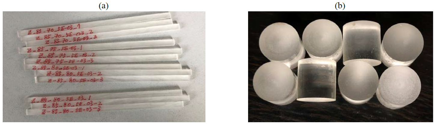 Fig. 2. Partially cured tensile and compressive test specimens.
A self-made rotary draw bending device schematically depicted in Fig. 2 was used for the composite bending experiments. Exchangeable mold rolls allow adaption of the bending radius. Curvature can be varied by selecting the rotation angle. In order to generate elevated temperatures the draw bending device and the specimens are placed in a convection oven. Prior to the bending operations, the oven doors were opened. Hence, a slight temperature drop during deformation is possible.
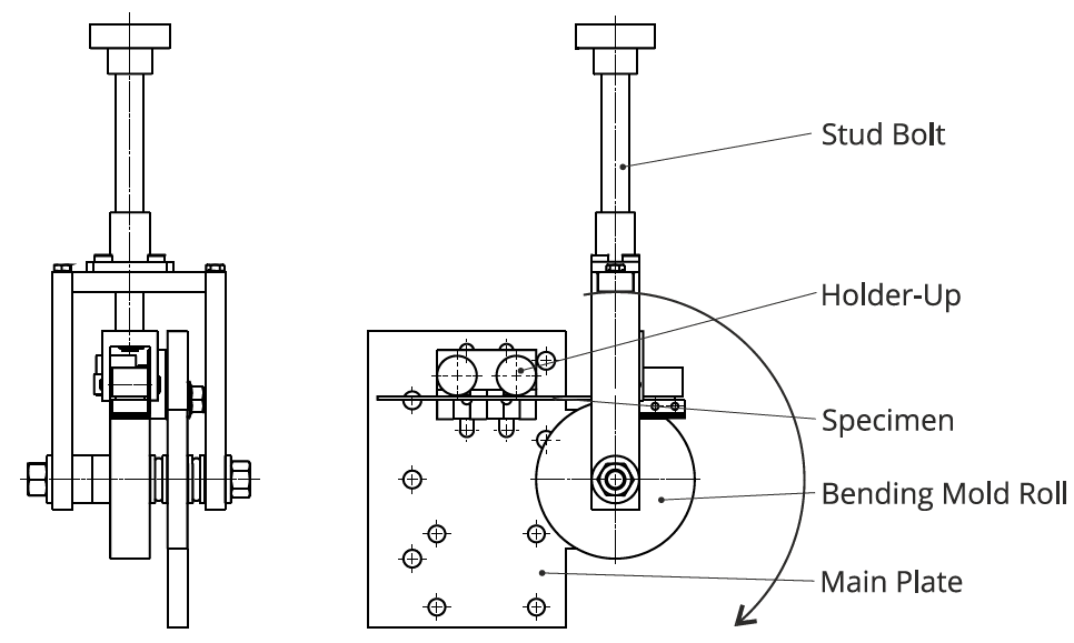
Fig. 3. Rotary draw bending device used for bending experiments
3 Results
3.1 Reaction Kinetics and Cure-Dependent Glass Transition
The exothermal heat flow data measured during DSC scans are used to develop a reaction kinetic model according to the methodology from [11]. The autocatalytic model

is chosen, containing four fitting parameters. E represents the activation energy, A is the pre-exponential factor, n is the reaction order and m is the autocatalytic constant. The universal gas constant R is a constant. Furthermore, cure-dependence of the glass transition temperature is described by the DiBenedetto equation:

which comprises another three parameters. 𝑇g0 is the initial glass transitions at p=0, 𝑇g∞ is the ultimate glass transition at p=1 and λ represents the DiBenedetto constant. The results of the fitting operation are given in Table 2.
Table 2. Parameters for the kinetic reaction model and the DiBenedetto equation

Depending on the heating rate the crosslinking reaction occurs between 60 °C and 250 °C. Experimental and model-based data are in good agreement (Fig. 4a). The glass transitions temperature can be described in good accordance with the experimental data by the DiBenedetto equation (Fig. 4b).
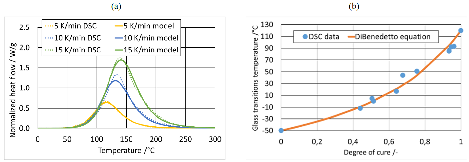 Fig. 4. Reaction behavior of the epoxy resin: (a) comparison of DSC data and model prediction, (b) cure-dependence of the glass transition
3.2 Tensile and Compressive Tests
The test temperatures used for quasi-static experiments were selected according to the determined glass transition temperatures. It is expected that the temperature difference (𝑇 − 𝑇𝑔) dominates the plastic deformation behavior. For partially cured specimens 𝑇𝑔 will be not exceeded in order to prevent post-cure. Temperature between 20 K and 5 K below 𝑇𝑔 were selected. The fully cured specimens were subjected to an additional test 10 K above 𝑇𝑔. Three specimens were tested for each configuration.
Table 3. Test temperatures for the quasi-static tests
As no necking was observed, true strain und true stress data for tension denoted εttr and 𝜎ttr 𝜎 as well as for compression denoted εctr and 𝜎ctr were calculated according to eq. (4) to (7) using the measured values for crosshead displacement Δl and force F:

In Fig. 5 (a-c) representative true stress-true strain curves of the performed tensile tests are shown. After an initially linear stress increase, which is associated with the elastic part of deformation, a maximum is reached followed by a drop of the measured stress values, which is probably related to intrinsic strain softening [12,13]. Both, the maximum and softening can be attributed to initiation of plastic flow. At low test temperatures, the resin shows higher stiffness and tends to brittle failure behavior. With increasing test temperatures, a transition from brittle to ductile behavior is observed. In this case, stress maximum and softening are followed by a rehardening. An increased DOC leads to a reduced modulus, yield stress and elongation at break. In Fig. 5 (d-f) the complementary true stress-true strain curves derived from compression tests are depicted. All specimens revealed a high degree of plasticity and ductile failure. The previously observed sequence of linear-elastic deformation, stress maximum, softening and rehardening is found again. Furthermore, the decrease in stiffness, yield stress and elongation at break with increasing DOC could be confirmed. Due to the lateral expansion of the specimens, maximum forces of more than 20 kN were recorded.
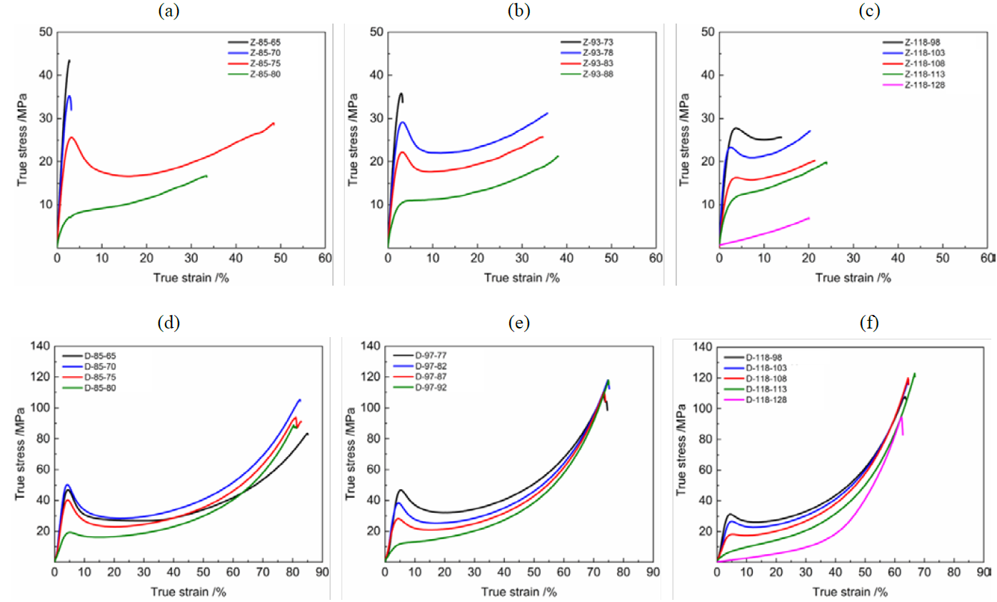 Fig. 5. Stress-strain curves determined in tensile and compressive tests at elevated temperatures using partially cured neat resin specimens
The elongation at break 𝜀𝑏 is expected to be of major importance for the deformability of the fiber reinforced epoxy resin. Hence, in Fig. 6 the measured results for 𝜀𝑏 are shown in dependence on 𝑇𝑔 and test temperature indicated by(T - Tg). It can be concluded that the lowest 𝑇𝑔 of 85 °C is best suited to realize large plastic deformations. While in tension mode, a maximum 𝜀𝑏 of 43 % was reached 10 K below 𝑇𝑔, in compression mode a maximum deformation of 90 % was possible when a test temperature 15 K below 𝑇𝑔 is used. With regard to temperature-induced post-cure during testing, it should be noted that a slight increase of Tg is possible. Preliminary analyses conducted with a comparable resin system revealed a Tg increase of 6 K after 10 min exposure to a temperature 5 K below Tg [10]. 10 K below Tg its increase is limited to 2 K in 10 min.
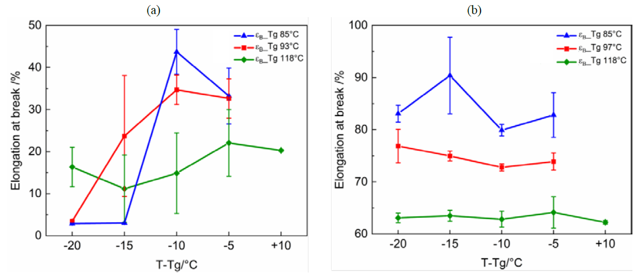
Fig. 6. Elongations at break determined in (a) tensile and (b) compressive tests in dependence on temperature and DOC
3.3 Bending Tests on Composite Specimens
The gathered knowledge from thermo-analytical and mechanical neat resin characterization was subsequently transferred to bending experiments on CFRP specimens. Table 4 compares the varied parameters with the results. Roll diameters of 32 mm and 48 mm were selected. Partially cured composite material with a Tg of 93 °C was chosen for both lay-ups. The test temperatures were determined iteratively starting with the most promising temperatures found during neat resin characterization. The initial bend angle was adjusted manually by rotating the stud bolt. After expiration of a defined dwell time at the initial bend angle, the specimen was unloaded, removed and measured. The results are presented by evaluating the final bend angle after unloading and the occurrence of damage patterns like fiber kinking, wrinkling or resin cracks (Table 4).
The specimens with ±45°-reinforcement showed overall good formability. Both tested temperatures of 80 °C and 90 °C resulted in predominantly plastic deformation. An initial bend angle of 90° and a roll diameter of 48 mm yielded a final bend angle between 84° and 88°. No visible damages occurred (Fig. 7a). An increase dwell time from 10 min to 30 min slightly improved the results.
Table 4. Parameters and results of the rotary draw bending experiments on composite specimens
|
Lay-up |
Tg (°C) |
Test temperature (°C) |
Roll diameter (mm) |
Dwell time (min) |
Initial bend angle (°) |
Final bend angle (°) |
Damage occurred? |
|
[45°/-45°/45°]S |
93 |
80 |
32 |
10 |
90 |
84,5 |
No |
|
[45°/-45°/45°]S |
93 |
90 |
32 |
10 |
90 |
87,5 |
No |
|
[45°/-45°/45°]S |
93 |
80 |
32 |
30 |
90 |
88 |
No |
|
[0°6] |
93 |
90 |
48 |
30 |
60 |
- |
Yes |
|
[0°6] |
93 |
120 |
48 |
30 |
60 |
- |
Yes |
|
[0°6] |
93 |
140 |
48 |
30 |
60 |
18 |
No |
In contrast to the ±45°-specimens, the material with 0°-reinforcement revealed rather elastic behavior leading to notable spring back after unloading. The previously used parameters were not suitable to avoid failure. To solve this problem, a reduced initial bend angle of 60° and a roll diameter of 48 mm were chosen. The specimens tested at 90 °C and 120 °C still showed fiber wrinkles and matrix failure on compression side (Fig. 7b). At a further increased test temperature of 140 °C, damage could be avoided, while the amount spring back remained comparatively high. A final bend angle of 18° could be reached.
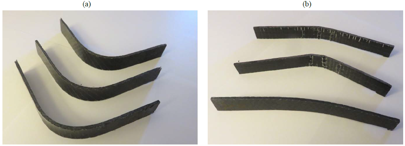 Fig. 7. Exemplary results of the bending experiments on CFRP composite specimens with (a) ±45° and (b) 0° reinformcement
4 Conclusion
Sustainable buildings and resource-efficient manufacturing processes represent essential challenges for future construction industry and architecture. In this context, novel rebars based on high-performance materials like CFRP are subject to current research efforts aiming at improved durability, increased design freedom and lightweight design.
In order to contribute to the required development of flexible and economic manufacturing methods, this work suggests introduction of secondary forming of thermoset-based CFRP rebars as a novel process. For this purpose, a commercially available epoxy resin system was selected and thoroughly characterized. Based on the assumption, that partial cure and elevated temperatures enable a notable increase in plasticity, a characterization program comprising thermo-analytical and mechanical tests was designed. DSC scans were used to develop a reaction kinetic model and to derive adapted cure cycles resulting in partially cured specimens. Neat resin specimens were prepared and used for quasi-static tensile and compressive tests at elevated temperatures. It was found that formability increases significantly when the glass transitions temperature is approached. In addition, a reduced degree of cure has a beneficial effect on plastic deformation potential. Crossing the Tg does not further increase the elongation at break of the neat resin. The gathered knowledge was transferred to bending experiments on CFRP stripes. Specimens with a reinforcement diagonal to the bending axes showed a high degree of plasticity and were unsusceptible to damage when deformed 10 K below and at Tg. Using a rotary draw bending device with a roll diameter of 32 mm, bend angles close to 90° were reproducibly realized. In contrast, specimens with a rebar-like reinforcement in 0°-direction were much more challenging to bend as they reveal fiber-dominated behavior. After some iterations, a temperature increase wide above Tg allowed a deformation to a bend angle of 18° without causing any damage.
Regarding these results, the feasibility of the initially envisaged functionalization of CFRP rebars by secondary forming require a nuanced assessment. On the one hand, the realization of structures with small bend angles like stirrups seems to remain difficult. On the other hand, a slight bending of CFRP rebars for use in shell constructions (cf. Fig. 1) appears to be indeed possible.
Further research is required to confirm the presented results. For this purpose, it is planned to perform bending experiments on rebars with circular cross section in order to further define the process window for secondary forming of thermoset based CFRP.
Acknowledgements
This research was funded by the Federal Ministry of Education and Research (project V4.16) within the Carbon Concrete Composites (C3).
