1 Introduction
Most modern electronic circuits in the industry are manufactured using printed circuit boards (PCBs). The PCBs are produced from glass-fiber-reinforced epoxy laminate with multiple copper layers. The cooper layers link the electronic components together, forming a circuit. The present work intends to contribute to the mounting techniques for PCB post assembly. For mounting electronic components in PCBs, fastening processes are commonly used based on drilling holes through the board to place them or attach various electrical components [1].
The Friction Riveting technique is proposed as an alternative to the press-fit technology for the assembly of components in PCBs. The frequently used press-fit technology for assembling of components on PCBs is a solder-free electrical assembly process. A pin is generally inserted tightly into a slightly smaller hole; the interference generated is enough to hold both parts in place and results in very good electrical and mechanical properties [2]. However, this method has some limitations, such as the number of processing steps, the need for pre-drilled holes on both sides of the plate, the use of an anvil, and connecting/mating screws [3].
Given the limitations of press-fit fasteners, Friction Riveting has been identified as a potentially advantageous alternative. The main benefits of using Friction Riveting in PCBs are the reduced number of process steps and shorter joining cycles, no need for pre-drilling and access form one single sides of the plate only. The friction-riveted fastener is directly anchored within the PCB through a single entrance with no mating screw required, leading to a decrease in component weight.
Friction Riveting is a metal-polymer hybrid joining technology, developed and patented in 2007 by the Helmholtz-Zentrum Geesthacht (HZG) [4-5]. The method is based on the principles of mechanical fastening and friction welding. One or more thermoplastics or composite components are joined with a cylindrical metallic rivet through frictional heating and pressure, where the former causes the rivet to plasticize and deform [6-10]. The feasibility of Friction Riveting has been demonstrated for a substantial number of material combinations and applications, but never for electronic applications. Studies have been conducted with hybrid friction-riveted joints of different aluminum alloys with unreinforced thermoplastics (Polyetherimide, PEI [11], and Polycarbonate, PC [8]). Additionally, the technique was also successfully applied in reinforced polymer, carbon, and fiberglass laminates (e.g., GF-PEI [12]; CF-PEEK [7], GF-PA6 [9], GF-P [10]) joined with titanium and aluminum rivets.
This work aims to study the joint formation of AA-2024-T3 rivets and FR4 laminates with single and double copper layers. The feasibility study follows a one-factor-a-time (OFAT) approach for parameter screening and optical microscopy (OM) to assess the joint formation of deformed rivet inside the laminates through the volumetric ratio (VR). The temperature evolution was recorded to understand the results of joints’ microstructure and local mechanical properties. The global mechanical behavior of the frictionriveted joints was analyzed by tensile testing.
2 Materials and Methods
2.1 Rivets
AA-2024-T3 extruded plane rivets were used with a diameter of 5 mm and a length of 60 mm. Table 1 presents the chemical composition of AA-2024-T3. The melting point of this aluminum alloy is between 502°C (solidus) and 638°C (liquidus) [13]. Fig.1 illustrates the microstructure and microhardness of the rivet material. The microstructure is characterized by elongated grains due to the extrusion process. A homogeneous hardness distribution is present with values around 155 𝐻𝑉 .
![Table 1. Chemical Composition of AA2024-T3 rivets [13].](docannexe/image/4327/img-1.png)
Table 1. Chemical Composition of AA2024-T3 rivets [13].
![Table 1. Chemical Composition of AA2024-T3 rivets [13].](docannexe/image/4327/img-2.png)
Fig. 1. a) Microstructure and b) microhardness map of the AA 2024-T3 rivet in the extrusion direction.
2.2 Glass-reinforced Epoxy Resin Laminate (FR4-PCB)
Glass-reinforced epoxy resin laminates, the most used material for PCB confection, with single copper layer on one side and double copper layer adhered to either board side were used to manufacture the joints. These PCB materials are named FR4 by NEMA (National Electrical Manufacturers Association, USA), where ‘FR’ stands for flame retardant material [14]. The thickness of the used plates is 1.5 mm, which is among the highest of PCBs commercially produced. The FR4 glass fiber epoxy is the most popular and versatile material used in PCBs, mainly because of the good resistance-weight ratio and the capacity to keep the high mechanical strength and the good insulating in humid environments [15]. Fig. 2 illustrates the FR4 microstructures used in this study, with double (Fig. 2a) and single copper layer (Fig. 2b), alongside the sketch of Cu-layer-FR4 distribution along the material thickness.
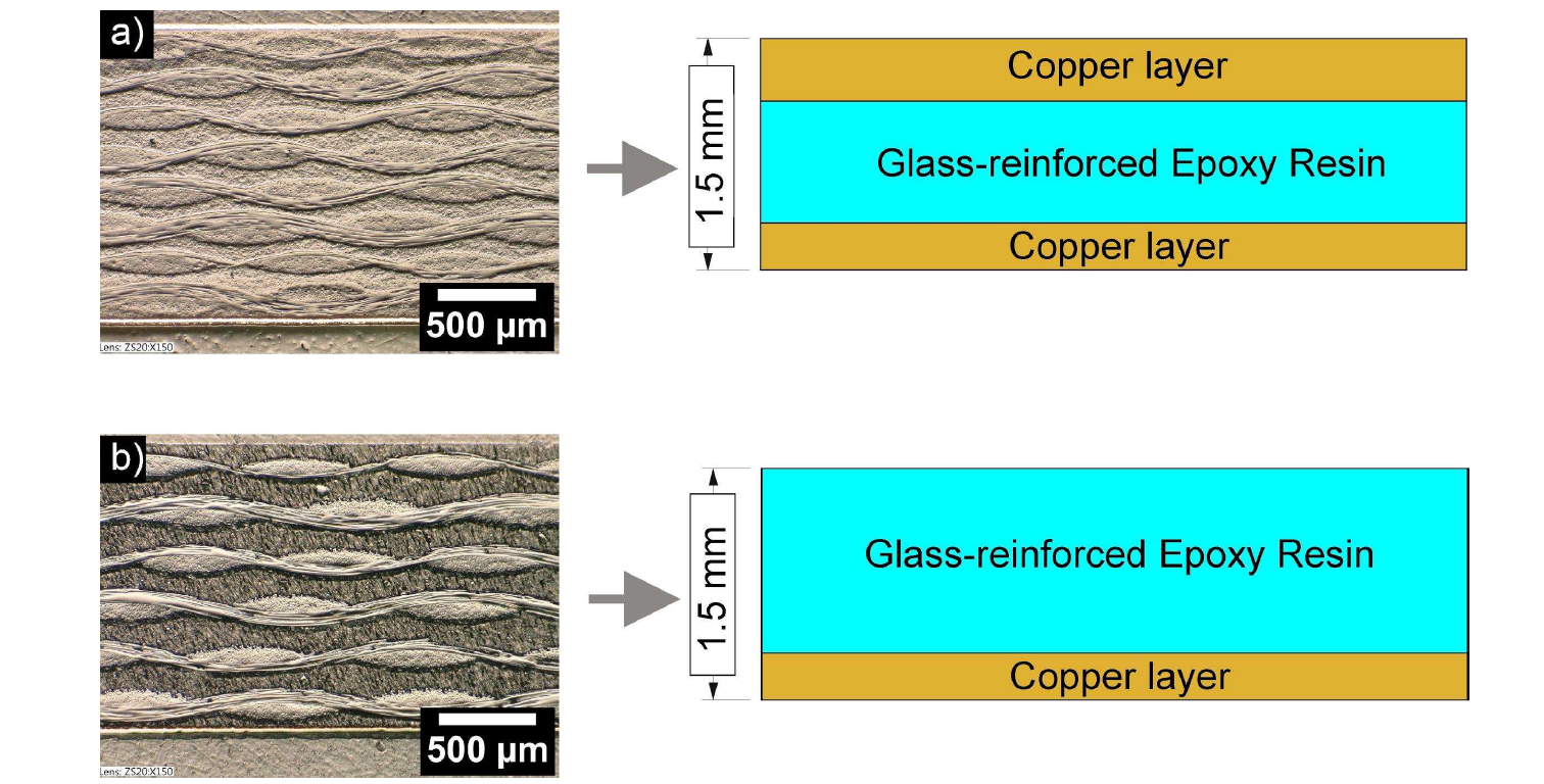
Fig. 2. The microstructure of glass-fiber-reinforced epoxy laminates (FR4-PCB) with a) double and b) single copper layer, alongside the sketch of Cu-layer-FR4 distribution along the material thickness.
2.3 Friction Riveting
The hybrid joints of AA-2024 rivets and FR4-PCB laminates were produced using a Friction Riveting laboratory equipment (RNA, H. Loitz-Robotik, Hamburg, Germany). A sample holder with a pneumatic clamping system (DZF-50-25-P-A-FESTO, Islandia, NY, USA) was used to fix the overlapped FR4 plates. This work adopted a direct-Friction Riveting process variant controlled by force and limited by spindle displacement [9],[16]. In Fig. 3, the schematic description of the Friction Riveting process is shown. The technique is based on frictional heating, resulting from the rivet rotation and its insertion into polymeric or composite parts (Fig. 3b). Forging force is applied when the metallic rivet tip is plasticized, deformed, and consequently anchored (Fig. 3c), resulting in a consolidated joint (Fig. 3d) [6].

Fig. 3. Schematic description of the Direct Friction Riveting process: a) positioning of jointing partners, b) rivet insertion into the polymer (friction phase), c) rivet plastic deformation (forging phase), and d) joint consolidation.
The joints were produced by varying three main parameters of this process variant: rotational speed (RS), displacement at friction (DaF) and joining force (JF). RS is varied between 6000 - 18000 rpm, DaF between 0.50 - 3.50 mm, and JF from 2000 to 4000 N. A one-factor-a-time (OFAT) approach was applied to obtain a combination of joining parameters until valid joints (deformed and anchored metallic rivet within the FR4-PCB plates) were obtained. Table 2 lists the two finally selected joining conditions investigated further in this work, characterized by a slight difference in the DaF values. The selected joining conditions have the purpose to show the significant difference in deformation and joint formation obtained by different plate stacking configurations and only minimal changes in displacement at friction (as a result of the reduced plate thickness). Condition 1 was applied to four FR4-PCB plates overlapping with double copper layers adhered to either side of the board. Condition 2 was used for two FR4-PCB plates overlapping with a single copper layer adhered to one side (lower side). It has to be noted, that the intention of the work was to produce overlapped joints of two plates. The additional two plates were intended to avoid welding of the rivet to the equipment’s working table in case of full perforation.
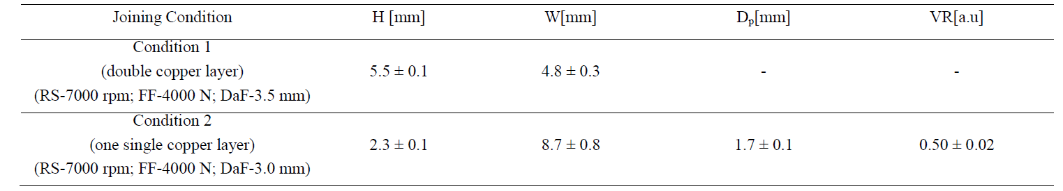
Table 2. Selected joining conditions investigated in this work.

2.4 Joint formation analysis
The joint formation of the AA2024-FR4-PCB hybrid joints was assessed by optical microscopy (LOM, Keyence VHX-6000, and Leica). The samples were prepared following standard materialography procedures. Mid-cross-section joint images were analyzed via LOM and measurements of the anchoring and deformation geometries were obtained: the maximum width (W) of the deformed rivet tip, its penetration (H) and the anchoring depth (DP) within the FR4-PCB plates. Including the original rivet diameter 𝐷, these values are used to evaluate the rivet anchoring efficiency by calculating the volumetric ratio (VR). VR describes the rivet anchoring considering the interaction volume between remaining plastic or composite material over the deformed rivet shape [17]:

2.5 Process temperature evolution, microstructure, and local mechanical properties
During the joining process, the temperature evolution was recorded on the softened material expelled as flash along the rivet shaft from the joining region employing an infrared camera (Image IR8800, InfraTec, Germany), using a filter gap between 150°C-700°C. The microstructure was analyzed by OM and the local mechanical properties were analyzed by Vickers microhardness (ASTM E384-992e1) [18].
2.6 Global mechanical properties
The joints’ global mechanical performance was investigated through assessment of the ultimate tensile force (UTF) by tensile/pullout testing. Tests were performed using a universal testing machine (100 kN load cell, Zwick Roell 1484, Germany) at room temperature and 1 mm/min transverse speed, in type “T” spot joint configuration, with 40 mm grip distance. This configuration uses a specially designed specimen holder manufactured, as shown in Fig. 4 [11]. Five samples manufactured from Condition 2 were tested, and their fracture behavior was analyzed.

Fig.4. T-pull tensile testing holder adapter used for the evaluation of the tensile force properties in Friction Riveting.
3 Results
Fig. 5 presents examples of the assessment of the joints’ anchoring zones within the mid-cross-sections for the two investigated parameter sets and material configurations. Three replicates were produced for each condition. The resulting geometrical properties, which characterize the joint formation, are summarized in Table 3. Fig.5a shows a representative joint geometry for Condition 1 (AA-2024-T3 rivet and FR4-PCB double copper layer), where the generated frictional heat resulted in drilling of the rivet through the four FR4-PCB laminates. The metallic rivet achieved 5.5 ± 0.1 mm of penetration depth into successive FR4-PCB plates without generating sizeable deformation of the rivet tip (W = 4.8 ± 0.3 mm, width of initial rivet diameter prior to the joining) and anchoring depth (DP = 0 mm), resulting in a joint with no volumetric ratio and the perforation of successive FR4 plates, therefore to a not successful Friction Riveting joint. Much improved joints were achieved for Condition 2 (AA-2024-T3 rivet and FR4-PCB single copper layer), see Fig. 5b. The slight change in DaF for Condition 2 had the purpose of reducing the rivet insertion depth to avoid successive penetration of multiple plates. Additionally, it is intended to verify if the heat generated is sufficient to produce significant deformation of the rivet tip into FR4-PCB with less copper layers. The combination of parameters and material configuration achieved heat generation levels sufficient for effective anchoring of the rivet into two FR4-PCB overlapped laminates without perforation of more than two plates. The gap between the two overlapped FR4 plates was caused by the large deformation (from 5.0 mm to 8.7 ± 0.8 mm). The joints obtained show 2.3 ± 0.1 mm penetration, 1.7 ± 0.1 mm anchoring depth, and 8.7 ± 0.8 mm width deformation. A significant volumetric ratio (VR = 0.50 ± 0.02) was achieved at anchoring depths below 3.0 mm, the lowest thickness achieved with the Friction Riveting process so far.
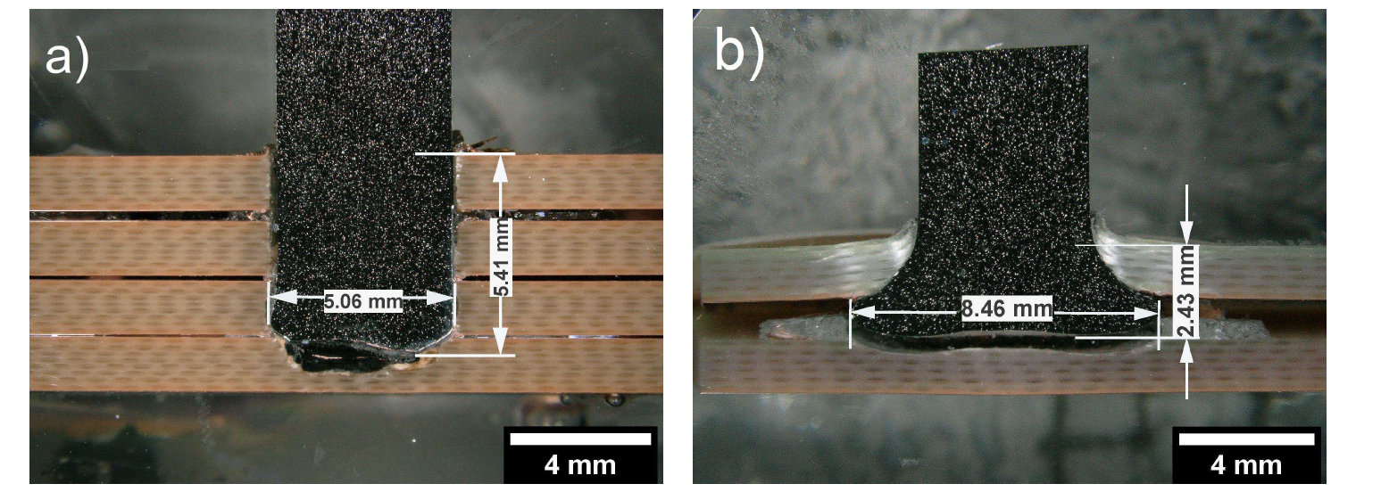
Fig. 5. OM-micrographs of joint cross-sections, produced with the joining conditions 1 and 2. H-values are related to the penetration depth and W-values to the deformation rivet tip of a) Condition1 (unsuccessful) and b) Condition 2 (successful joint condition).
Table 3. Geometrical features (W, H and DP) of the friction-riveted joints and calculated volumetric ratio, VR.
The different joint formations achieved might also be related to the strong anisotropic character of the FR4-PCBs material due to the significant difference between cooper and glass-epoxy thermal properties [19]. The placement of single or double-layer in the board significantly influences the generated heat during the Friction Riveting process, as the process starts with an initial Coulomb friction and subsequent changes in material viscosity during the rivet insertion.
Fig. 6 shows the process temperature measurements via infrared thermography (Fig. 6a) and the average peak temperatures (Fig. 6b) recorded on expelled flash material from three joint replicates manufactured with Condition 2. The average temperature obtained was 362 ± 7 °C, which is approximately 70% of the rivet melting temperature, which lies within the range of measured temperatures in friction welding based techniques applied to this alloy [13][20]. The temperature achieved shows that the generated heat is sufficient to promote the rivet deformation despite the minimal material thickness..

Fig. 6.a) Infrared thermography of the process temperature development during Friction Riveting. b) Maximum average temperature (362 ± 7 ºC) measured on the expelled thermoset flash material from three joints produced for Condition 2.
Fig. 7a shows the microstructure and the Vickers microhardness distribution of an AA-2024-T351 deformed rivet from the joining condition depicted in Fig. 5b. Different microstructural zones have been identified, similar to the ones obtained in previous studies of friction-riveted AA-2024-T351 joints in thermoplastic materials [11]. It shows that joint formation can be achieved in both thermoplastic and thermosetting polymeric / composite materials. A statement prior considered impossible due to the nature of thermosets and their high flammability and no melting possibility. As shown in the work of Borba et al. [22], this is not the case with the use of additives in thermosetting composites, as is the case for FR4 (mentioned in Section 2.2).
Fig. 7b presents the thermo-mechanically affected zone (TMAZ) of the metallic rivet. A realignment of grains is observed in the direction of the flow of forged and plasticized volume of material. Partial grain refinement is also seen, characteristic for dynamic recrystallization in aluminum alloys, as reported for other friction-based welding processes [23-24] as well. In the metal heataffected zone (HAZ) (Fig. 7c), no visual microstructural changes have been observed (see base material in Fig. 1b). More investigations through electron microscopy are required in order to identify phenomena such as static recovery and re-precipitation [8]. This can be caused by recovery, recrystallization, re-precipitation or averaging [11],[25]. Other friction-based processes like friction stir welding (FSW) lead to similar changes, as demonstrated by Milčić et al. [26]. The undermatching of microhardness in Friction Riveting as well as FSW of AA-2024, generally below 10%, is typically observed [21].

Fig. 7.a) Microstructure features of a Friction-riveted PCB-FR4 single copper layer/AA-2024-T351 joint (Condition 2) and Vickers microhardness distribution of an AA 2024-T3 deformed rivet. b) Thermo-Mechanically Affected Zone of the metal, TMAZ, exhibits grain realignment in the direction of the material flow in the forged rivet tip c) Detail of the Heat Affected Zone of the metal, HAZ.
Rodrigues et al. [8] measured similar temperature ranges performing Friction Riveting process joining AA2024-T3 with polycarbonate and the metal microstructure presented the same transformations after the process. These microstructure changes can be observed in others friction based process as demonstrated by Amancio et al. [21] However, the microhardness (Fig. 7a, left) shows a slight reduction compared to the base material. Changes in microstructure and local reduction of mechanical properties within the metallic rivet might influence the global mechanical behavior of friction riveted joints, as reported previously [8],[9]. Nonetheless, the anchoring efficiency determined by VR is dominant for identifying potential good/weak joints, as it indirectly (metal-composite interface is not considered for VR) considers the interaction of the deformation (both depth and width) with the remaining composite material around and above the anchored deformed rivet [9],[27],[28]. The global mechanical performance of the FR4-PCB-AA-2024-T3 joints was assessed by tensile tests for samples manufactured by Condition 2. The ultimate tensile force is obtained as 828 N ± 65 N, with fracture occurring within the composite base material. A comparison with other combination of materials is not relevant, given that the plate thickness in this study despite being overlapped, is the minimum reported so far for Friction Riveting [29].
Fig. 8b shows the final failure in the FR4-PCB material. Based on previous works [22][8], this type of failure through FR4-PCB occurs due to plate bending, followed by delamination (Fig. 8b and d). Bending tests of FR4-PCB and fracture analysis using SEM will be performed in the future to confirm the features of this failure. Since the anchoring depth was lower than the initial rivet diameter, joint failure within the rivet was not expected, despite the reduction of local mechanical properties in the rivet. The fracture occurring within the composite material and not within the deformation legs nor the weakened metal HAZ proves the soundness of the anchoring efficiency by the VR approach, namely sufficient anchoring was provided to avoid the full extraction of the rivet. Nonetheless, the composite structure might have been affected, therefore further investigations will focus on the structural and physical-chemical changes within the FR4-PCB material as well as the interface between rivet and composite.

Fig. 8.a) T-pull specimen prior to testing, b) cross-sectional view of failure through PCB plate, (c) lower and (d) upper FR4-PCB parts after T-pull testing.
4 Summary and Conclusions
The current work investigated the joint formation and inherent deformation/anchoring of 5 mm diameter AA-2024-T3 rivets within overlapped 1.5 mm thick glass-fiber-reinforced epoxy plates (FR4-PCB) via Friction Riveting. The first results of the anchorages of AA2024 in FR4-PCB are considered very promising. It was possible to achieve well-anchored joints, with 60% of the rivet tip deformed at 2.43 mm penetration depth in the FR4 laminate. The joints present significant anchoring efficiency (volumetric ratio VR=0.50 ± 0.02), achieved at thicknesses and anchoring depths below 3.0 mm, which is considered the lowest depth achieved so far with Friction Riveting. The maximum process temperature (362 ± 7ºC, approximately 70% of the rivet melting temperature) was sufficient for effective deformation and consequently mechanical anchoring of the rivet. The heating and the applied process forces resulted in microstructural changes and reduction of local mechanical properties, with grain refinement and realignment within the deformed rivet tip. The joints’ mechanical performance was evaluated in terms of ultimate tensile force, reaching 828 N ± 65 N, with failure occurring through FR4-PCB due to plate bending, followed by delamination. The rivet anchoring was sufficient to withstand the potential full extraction of the deformed metallic insert joint, which was prior demonstrated as the weakest joint behavior in all previously tested material combinations for Friction Riveting. Therefore, the mechanical anchor achieved in this work can be regarded as efficient.
This work constitutes a premiere by showing that it is possible to deform metallic rivets within thin composite plates at diameterto-thickness ratio below 1:1. Further works will investigate in depth the metallurgical changes in AA-2024-T3, the PCB-rivet interface, and the failure mechanisms related to tensile/pullout testing in this combination of materials and similar, alongside the changes in physical-chemical and electrical properties.
Acknowledgements
This work is supported by the HZG technology transfer fund in cooperation with Panasonic Industrial Devices Europe GmbH within the "FricBoard" project. This support is gratefully acknowledged.
