1 Introduction
In manufacturing technology, energy and resource efficiency during the production and application of products is becoming increasingly important, and this calls for intelligent lightweight design. Weight reductions can be achieved through the use of different lightweight construction strategies. Locally adapted material properties and component dimensions [1], as well as multi- material designs [2], can significantly reduce the weight of a product while maintaining its functionality and safety. This leads to a composite structure with a wide variety of materials and the use of tailored blanks, while making the joining task an important and sensitive production step [3].
Because thermal joining methods have severe limitations when it comes to joining dissimilar materials [4], mechanical joining processes are widely used for multi-material design applications [5]. Product life cycles are becoming shorter, and hence it is important to select the right joining technique early on in the concept design phase already [7]. To achieve the target weight for a new lightweight structure, it is important to choose the right materials for the specified mechanical loads and functionality. When selecting the appropriate joining technology for a multi-material design, this will frequently be a mechanical joining technique. Due to the wide range of material properties and the frequently application-specific suitability of mechanical joining technologies, computer-based selection of the right combination of material and joining technique can be helpful and even indispensable at the concept phase [8].
The use of a combined joining method employing a structural adhesive and a local mechanical spot joining technique (e.g. self- piercing riveting) is a highly effective way of joining multi-material combinations like aluminum and high strength steel [6]. Research into the fatigue life of hybrid-joined multi-material connections shows that the most favorable dimensions for the mechanical point joint will differ depending on the load case (lap shear, coach peel, static, cyclic or dynamic) [9]. Not only the shape of the auxiliary joint connector but also the mechanical properties of an identical geometry can have a big impact on the strength of the joint [10]. Most of the auxiliary joint connectors used in mechanical joining are made of steel, although there are investigations into the use of aluminum self-piercing rivets for homogeneous aluminum joints [11,12].
Manufacturing auxiliary joint connectors for the mechanical joining technologies (e.g. self-piercing riveting) is time-consuming and cost-intensive, since it involves several steps, such as forming, hardening and coating. Approaches are being adopted to reduce the manufacturing outlay by using corrosion-resistant and high strain hardening material [13].
So far, in order to optimize the joint strength and condition for a lightweight, optimized multi-material design as a function of the loading condition, the sheet wall thickness and the material combination, it has been necessary to try out a wide variety of joining techniques and an even greater range of auxiliary fasteners. To lower these high diversification costs for multi-material design, it would help significantly to enhance the variability and versatility of the mechanical joining technique used. Increased versatility in mechanical joining is the main reason behind the use of the friction-spinning technique in both the production of the auxiliary connectors and the joint setting process itself.
2 Process Principles
The friction-spinning process, which is used to custom-form the joint connector, uses the (self)-induced friction heat to reduce the flow stress of the material and thus extend the forming possibilities and reduce the process forces. The fundamentals of friction- spinning can be found in [14-16]. Fig. 1 shows the forming of the Friction-Spun Joint Connector (FSJC) in the first row and the joint setting in the second row, employing the friction-spinning technique in each case. During the forming process, the friction is generated by the rotating rod, which can be fed in as an endless semi-finished product and clamped in the collet and the rigid friction-spinning tool. The thermo-mechanical kinematic shaping is realized through the rotation of the rod and a two-way linear controlled kinematic between the universally applicable forming tool and the collet. The correct process control will also permit the mechanical properties of the FSJC to be adjusted. The joining takes place subsequently, with the same clamped position for the FSJC and the collet, and similarly employing the friction-spinning technique. In the final step of the joining process the separation of the FSJC takes place.

Fig. 1. Process principle of FSJC forming and the setting of the joint, including closing head forming and separation of the initial material.
3 Results
3.1 Analysis and concept of suitable FSJC geometry element
An analysis of current mechanical auxiliary joining parts shows that three general forms can be distinguished – “nail-shaped”, “solid-rivet-shaped” and “hollow-rivet-shaped”. Each general form can also be divided into the sub-geometries of “head”, “shaft” and “tip”. An analysis of the wide variety of auxiliary connectors in use revealed sub-geometries that are suitable for manufacture by friction-spinning, and these have been set out in a systematic manner on the left of Fig. 2.
The sub-geometries were subsequently checked in a feasibility study. This study revealed a wide variety of shapeable sub- geometries for serviceable FSJCs using rods and tubes with an initial diameter D₀ that ranged from Ø 14 mm to Ø 8 mm, made of aluminum EN AW-6060 in a T6 condition. The photo in the centre of Fig. 2 shows a selection of different part geometries, including different angled tips, hollow and grooved shafts and different-shaped heads. Combinations of these can be shaped using the same universally applicable forming tool. Studies of different initial rod diameters have shown that, due to the interdependency of the rotation radius and the friction speed, the number of shapeable geometries decreases with a smaller initial rod radius for the same process parameter settings in respect of the rotational speed and feed (in the parameter range of: D₀ = 8 -14 mm; n = 300 – 900 mm-1 ; vf = 15 – 240 mm/min).
After the feasibility tests had been carried out on the conventional friction-spinning test stand, further studies were transferred to a conventional CNC mill. While the friction-spinning stand is restricted in terms of the rotational speed (n max = 900 rpm) and feed range (f max = 240 mm/min), the CNC mill (DMU 50 from German company DMG Mori (n max = 10000 rpm; f max = 24000 mm/min)) can significantly extend the process limits, especially for rod diameters smaller than Ø10 mm, which are the usual dimensions employed in mechanical joining techniques.
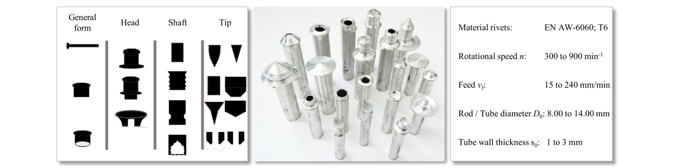
Fig. 2. A number of samples of general shapes and local part geometries of possible FSJCs (left); a selection of different realized part geometries produced with the help of friction-spinning (centre); used parameter range (right).
After the feasibility tests, the influence of different parameter sets on the mechanical properties was analyzed. Different rotation speed and feed settings, with an identical tool path, were thus used to shape the same FSJC. The top row in Fig. 3 shows an example of an FSJC geometry with a flat tip, a subsequent reduction in the outer diameter and an intermediate flange shape, together with the hardness measuring points in the cross section as well as the tool path and the parameter sets for this geometry. During the forming process, the temperature was recorded with a thermographic camera (VarioCAM hr from InfraTec). In the bottom row of Fig. 3, the temperature curves of the different parameter sets are depicted for a specific point, together with the maximum temperature during the shaping process. The curve progressions for the maximum temperature display similar characteristics for all the parameter sets. After an increase with a short peak and cooling between the pre-heating phase and the short diagonal run, the temperature then rises to its maximum. At this point, the reduction in the outer diameter and the shaping of the intermediate flange has been completed. It is obvious that the maximum temperature depends on the level of the friction speed and the applied time. The highest temperature thus results with the maximum rotation speed and the slowest feed (Tmax = 401 °C for nmax = 900 rpm and vf = 15 mm/min).
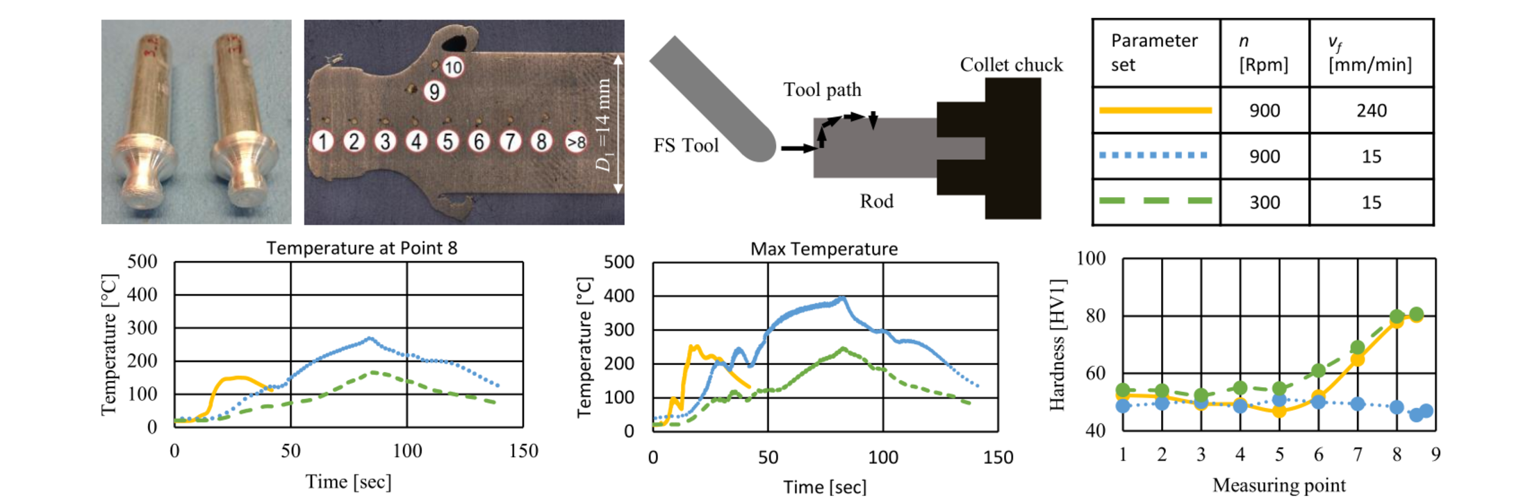
Fig. 3. Influence of the process parameters on energy input and hardness while shaping geometrically identical FSJCs in aluminum EN AW-6060 T6.
The varying amount of induced thermal energy leads to locally differing mechanical properties. In the case of the aluminum employed, it is the material softening range that varies. The hardness diagram for the three parameter sets (Fig. 3 right bottom) shows that, up to measuring point 5, the hardness is at an approximately constant low level. This can be explained by the temperature increase to at least 250 °C up to this point. The different hardness levels from measuring point 6 onwards are conditioned by the temperature flow within the sample. The temperature progression at point 8 (Fig. 3 left bottom) and the corresponding hardness indicate that the initial hardness can be retained if the temperature is kept below approximately 170 °C.
3.2 Manufacture and joint setting of FSJCs in pre-holed joints
Two basic rivet geometries were chosen for the joint-setting experiments with pre-holed sheets. On the one hand, the solid shaft rivet was chosen as a simple geometry for adjusting the shaft length and diameter to the different sheet thicknesses being joined and to the different volumes used to form the closing head. And, on the other hand, a hollow shaft rivet was selected for force- reduced interlock forming, using a spindle die for the shape guidance during interlock forming. The cross-sections of both basic rivet shapes are shown in Fig. 4, together with a corresponding hardness profile. Fig. 4 also shows a photo of a solid shaft variant with a pointed tip. The additional forming step required to shape the hollow shaft entails a higher heat input, which leads to greater softening of the base material of the rod. Both rivet variants are made from an extruded rod with an outer diameter of 8 mm in aluminum alloy EN AW-6060 in a T6 condition. To form the shaft, the rod is reduced by approximately 50 % through friction spinning.
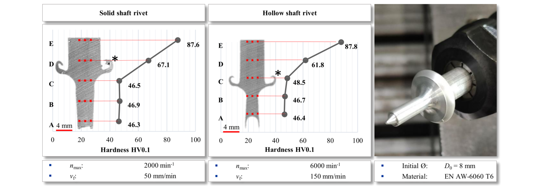
Fig. 4. Cross-sections of the two different rivet shapes and the hardness evolution towards the initial hardness (left and middle); inline photo of a clamped solid shaft rivet (right).
For inline rivet manufacture and joint setting in a single clamping step, two tool setups were mounted on the mill table (Fig. 5, left). The friction-spinning station holds differently dimensioned and oriented universally applicable forming tools to permit a high flexibility in shaping plus an optional turning tool to dress the rod between the joining steps. The joining station in the case shown has a lap-shear specimen holder with an integrated die-holding fixture for exchangeable die geometries (Fig. 4, right) and two sets of blank holders. One of these holds the sheets in position while the other prevents a gap formation during the joining process. To monitor the joining force, a load cell is positioned under the sample holder.
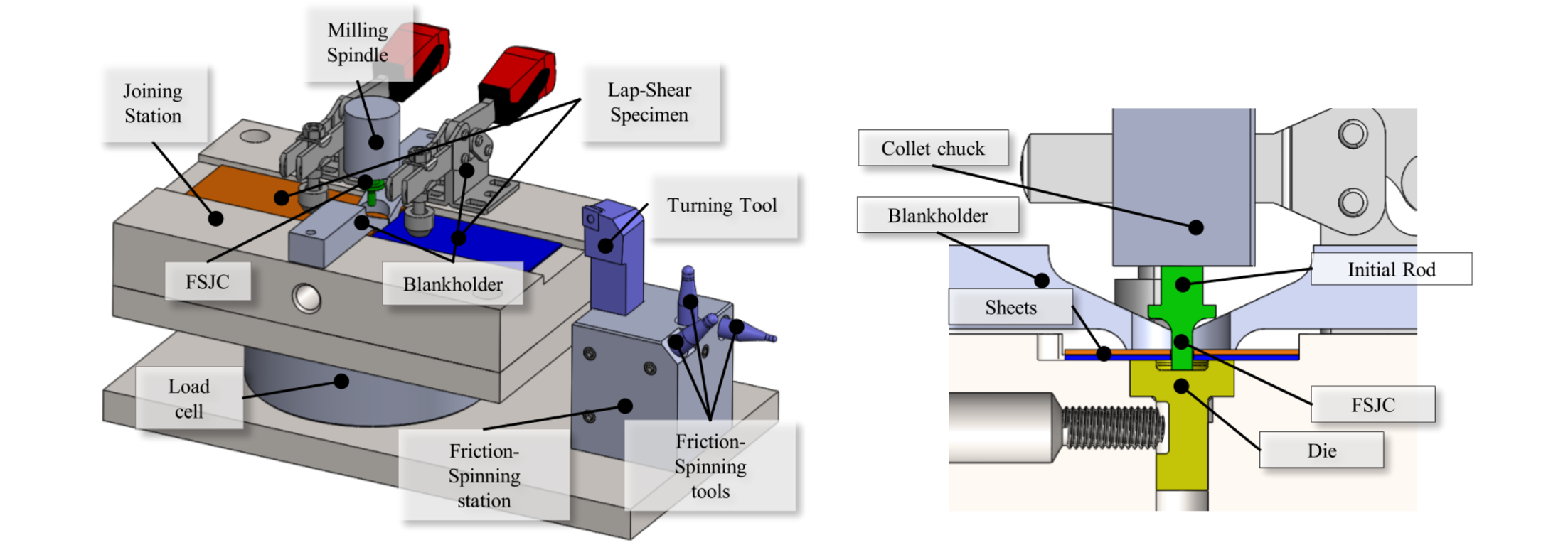
Fig. 5. Tool setup for the shaping and joint setting sequence (left); sectional view of the joint setting assembly (right).
The shape and length of the FSJC can be formed to meet the specification for the next joint to be performed, as a function of the sheet thicknesses, the closing-head volume and the pre-hole diameter needed for the required joint strength. The shaft of the rivet is tapered slightly towards the tip so as to increase the buckling strength. Fig. 6 a) shows examples of varying shaft geometries for the two basic rivet shapes. Fig 6 b) shows a sample of a friction-spun closing head formed with a hollow rivet and a spindle die.
The bore hole diameter of the pre-holed sheets is slightly wider than the shaft diameter of the rivet in order to avoid friction between the shaft and the sheets during the plasticization phase for the FSJC tip and to localize the friction-induced heat in the closing-head area of the die as far as possible. In the upsetting phase, the shaft diameter will expand to fill the bore hole, so that the joint has a force fit component in the effective bearing area.
If, for example, the overall sheet thickness layers differ over the workpiece to be joined when using tailored blanks or a varying number of sheets, only the shaft length l Sh has to be adjusted. The volume of the shaft must therefore be equal to the total sum of the borehole and the die volume (Eq. 1)). The attainable shaft length is limited solely by the resulting buckling length. In this case, the buckling length for the pre-friction and closing-head forming phase is case I according to EULER, changing to EULER case IV as soon as the shaft is upset to the extent that it is led by the bore hole. Through the EULER case change, the buckling force can now be increased by up to 16 times for the final die filling without any buckling of the shaft.


Fig. 6. Samples of FSJCs with different shaft lengths and diameters (left) and a formed closing head of a hollow shaft rivet on a lap-shear specimen (right).
Fig. 7 shows two joint cross-sections for the basic rivet shapes by way of example. The die form is adjusted to the tip shape of the specific rivet, as a round and spindle die, with the maximum diameter 10 mm and the maximum depth 2 mm for both dies. The hardness of the joint connector increases through the deformation due to strain hardening but is still at a low level compared to the attainable hardness of this aluminum alloy. To enhance the joint strength, further research should be aimed at lowering the hardness reduction during the rivet shaping process and having the hardness increased during the joint setting step by optimizing the process control strategy. In the feasibility test, only the pre-friction phase has a different feed rate so far. One way would be to localize the induced heat in the tip of the shaft to a greater extent by specifying the process parameters for a greater number of individual setting phases. This way, a better filling level could be expected for the closing head and higher work hardening in the shaft area.
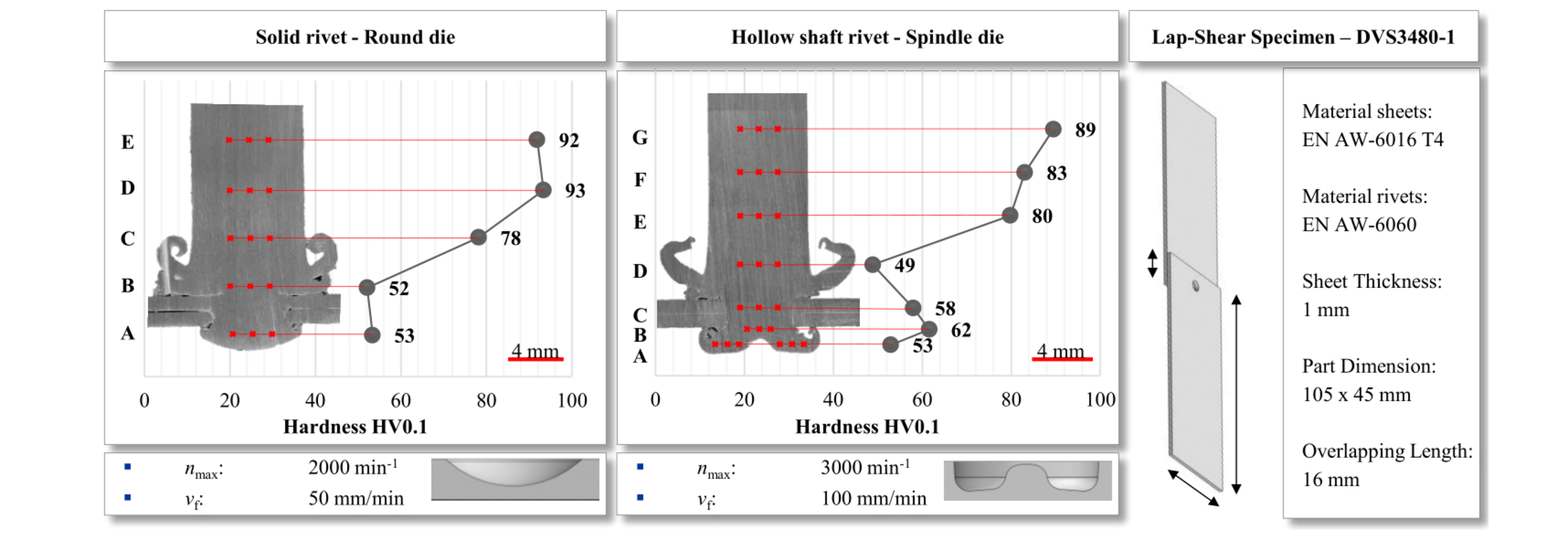
Fig. 7. Cross-sections of the two different closing-head forms (left and middle) and the geometry of the lap-shear specimen employed as per German standard DVS/EFB 3480-1 [17] (right).
The axial force in the joint setting process using aluminum rivets is pretty low compared to other mechanical joining techniques. The diagram in Fig. 8 shows two axial force progressions for the solid rivet joints with a round die depicted on the left of in Fig. 7. For relatively low feed speeds as shown in Fig. 8, the maximum force is more or less identical. For higher feed rates but equivalent rotation speeds, the axial force is considerably higher. The characteristic key points of the setting process are marked for the vf = 50 mm/min feed, but are also clearly recognizable in other feed speed force curves.
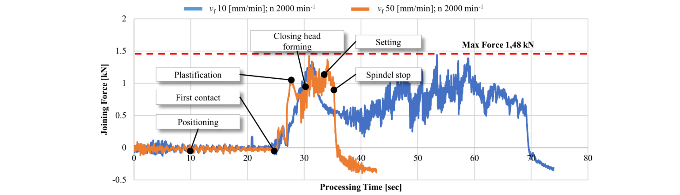
Fig. 8. Axial joining force progression for two different feed speeds for a joint setting of a aluminum solid shaft FSJC (EN AW-6060) in pre-holed aluminum sheets (2 x s = 1 mm).
4 Outlook
Further investigations will concentrate on optimizing the closing-head filling level and the corresponding die geometries in order to enhance the joint strength and stiffness by increasing the proportion of the form and force-fit component. In conjunction with this, the process management of the rotation speed and the feed variation over the setting path will be more aligned to the individual process steps. In addition, pre-hole-free joining with steel-FSJCs is the focus of ongoing studies. Proof of the feasibility of manufacturing basic steel (1.0503) solid rivets has already been furnished (see Fig. 9, left photo). In the next step, the specified part geometries, such as a ring groove head and circumferential grooves on the shaft have to be integrated into the rivet shape. The objective is to set FSJCs by friction-spinning without a pre-hole, either by using a die to form the closing head (Fig. 9 A) or without any countersupport or form-giving die when there is only one-sided accessibility (Fig. 9 B). In this case, the base plate has to have a certain stiffness, e.g. a thick-walled extruded profile.
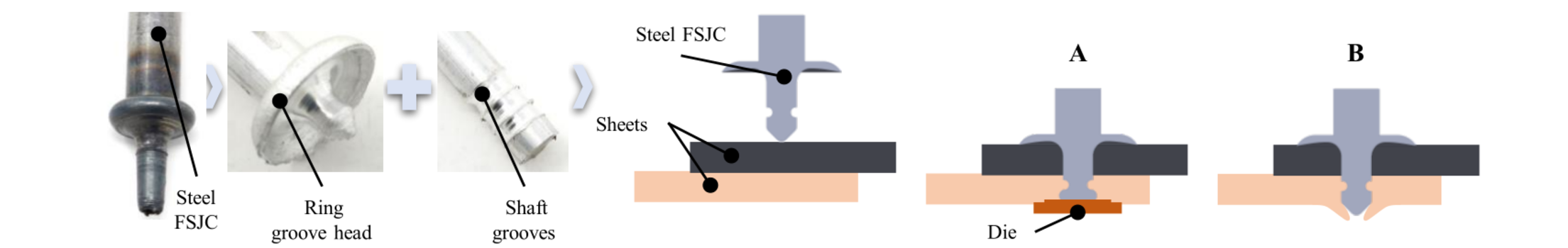
Fig. 9. Photo of a steel (1.0503) solid shaft rivet and aluminum (EN AW-6060) part geometries as a basis for the schematically shown pre-hole free joining concept with (A) and without (B) a die.
5 Conclusion
Studies carried out so far have shown that it is possible to form adjustable joint connectors by friction-spinning. Different basic rivet shapes can be inline custom-formed from the same semi-finished rod to best meet the requirements of the subsequent joining task. In this process, the dimensions of the rivet part-geometries can be adapted to the joint’s specification in terms of size and shape. First joints with aluminum FSJCs have been set in pre-holed aluminum sheets, whereby the joining force is significantly lower compared to other mechanical joining techniques for a comparable joint strength.
Acknowledgements
The authors from the subproject C03 centre of the collaborative research TRR 285 – Project-ID 418701707 –, carried out at the Chair of Forming and Machining Technology (LUF), Paderborn University, would like to thank the Deutsche Forschungsgemeinschaft (DFG, German Research Foundation) for funding this project.
