1 Introduction
As customer requirements increase, the demands on materials, tools and processes within manufacturing companies are rising [1]. Alongside the efficient use of resources, adaptation to customer needs plays an essential role in the manufacturing sector of metal forming today [1,2]. It is thus necessary to optimize the correlation between the material requirements and the material properties of a produced part. Using these material characteristics, it is possible to consider both the expected loads and the desired integrated functions and implement these on a local basis, thereby promoting material resource efficiency. Austenitic stainless steel offers favorable preconditions for this, since the metastable austenitic phase is not in an equilibrium state and can thus be transformed into α’-martensite with different properties in terms of mechanical and magnetic parameters through deformation- or temperature-induced energy [3,4]. The ferromagnetic nature of α’-martensite is fundamental for the work within this paper, since this can be detected and measured with micromagnetic measurement methods [5]. The objective of the first experimental investigations is to identify a correlation between the process parameters of a flow-forming process and the resulting deformationinduced α’-martensite content of the formed seamless tubes in metastable austenitic steel AISI 304L (X2CrNi18-9, 1.4307).
The main focus of this paper is on the influence of the process parameters of feed rate and wall thickness reduction per pass. The process parameters and the resulting deformation-induced α’-martensite content of the workpieces are presented in a data-based correlation model. The correlation model obtained from the experimental investigations within the scope of this work, will subsequently be integrated into the planned control loop and serve as a database of empirical data from previous experiments.
2 State of the Art
2.1 Flow-forming
Flow-forming is a process used to manufacture axisymmetric products on a rotating mandrel by plastically deforming a hollow metal blank, either in consecutive stages or in a single stage, with a number of co-rotating rollers generating the necessary deformation forces [6]. There are three processes in which spinning is applied: conventional spinning, shear forming using a flat metal sheet as the starting geometry, and flow-forming using tubes [7,8]. Another significant difference between flow-forming and conventional spinning, which is also an incremental forming technology, is the intended wall thickness reduction in flow-forming processes [9]. Reverse- and forward flow-forming are two main variations of tube flow-forming.
The configuration for the first variant results in an identical direction for the rollers’ axial movement and the workpiece material flow. Backward flow-forming on the other hand results in an opposing material flow [6]. Besides the axial flow, the material flow during flow-forming consists of radial and tangential components [10]. The ratio of these components depends mainly on the rollers’ attack angle, transition radius and exit angle [11]. Among others, Tsivoulas et al. [12] and Jahazi and Ebrahimi [11] have investigated the dependence of the rollers’ workpiece contact area and the resulting material flow. Their investigations indicate that the ratio of the axial to the radial material flow is determined by the ratio of the axial to the radial contact area of the roller and the workpiece. An analytical model for the calculation of the contact surface between the roller and the workpiece resulting from different roller geometry elements has been developed by Roy et al. [13]. Jahazi and Ebrahimi also found that the related feed rate influences the contact area ratio of the axial to the circumferential tool-workpiece contact in the forming zone [11]. Kleditzsch developed an analytical approach for calculating the equivalent plastic strain [14]. At present, no more detailed investigations on the phase transformation of metastable austenites by flow-forming are known.
2.2 Austenite-martensite phase transformation of metastable austenites
The austenitic stainless steel AISI 304L is composed of the metastable austenite phase (γ) with a face-centered cubic (FCC) lattice structure. During plastic deformation of metastable austenite, strain-induced ε- and α'-martensite phases can be produced [15,16]: Hexagonal close-packed (HCP) ε-martensite and body-centered cubic (BCC) α'-martensite [4]. The α'-martensite phase nucleates at the intersections of the shear bands [17,18].
The main factors affecting the strain-induced α'-martensite are the chemical composition [19], temperature [20], strain and stress (loading-dependent deformation) state, austenite grain size [21], and strain rate [22]. Magnetic measurements have been performed with a Feritscope and compared with microscopical analysis techniques and X-ray diffraction measurements [23,24]. Gorkunov et al. carried out a similar investigation by means of the magnetic Barkhausen noise method in plastically deformed austenitic stainless steel. It was found that, for an increment of strain-induced α'-martensite, the maximum amplitude of the measured Barkhausen noise signals undergoes an increase [25].
3 Experimental Investigations
3.1 Machine setup
All work-related forming operations took place on the flow-forming machine BD 40 from Bohner-Köhle illustrated in Fig. 1.
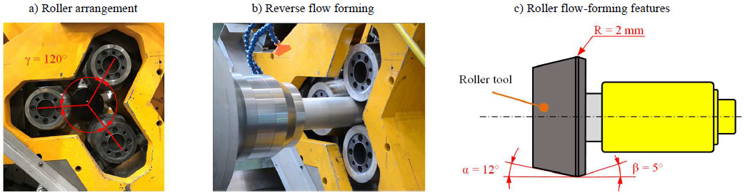
Fig. 1. Flow-forming machine setup.
The machine is equipped with three identical rollers, which are arranged at an angle of 120° to each other as shown in Fig. 1a. The rollers have all the essential flow-forming geometry features. These include an attack angle of α = 12°, a transition radius of R = 2 mm and an exit angle of β = 5°, as shown in Fig. 1c. For the external dimensions, a rolling diameter of 155 mm and a roller width of 80.3 mm can be measured. Three cooling hoses attached to the support ensure the alignment of the metal-working fluid jets during the forming process. The emulsion prevented the specimens from heating above room temperature. Fig. 1b shows the setup in motion during the process.
The forming was carried out according to the principle of reverse flow-forming demonstrated in Fig. 2. To simplify the illustration, only one of the three rollers is shown. Besides the mandrel, which has a diameter of 72 mm, the image illustrates how the tubes were positioned on it. As shown in Fig. 2, a positive-locking connection between the rotating spindle and the tube is what causes the tube to spin.
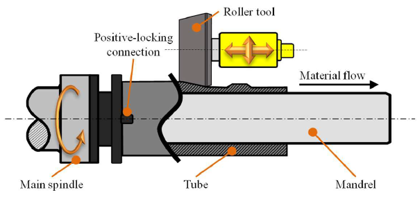 Fig. 2. Reverse flow-forming.
The semi-finished seamless tubes have an initial outer diameter of 80 mm and a wall thickness of 4 mm, although there are slight variations due to the eccentricity. Fig. 3 shows an example of a formed part from the DV test series which is described later on, to permit a better understanding of the flow-formed tubes. The image shows the different wall thicknesses resulting from a preset wall thickness reduction of 1 mm per pass. At this point, the focus is on the tube eccentricity that is shown, which leads to different initial wall thicknesses, e.g. w1 and w2, depending on the position on the tube circumference.
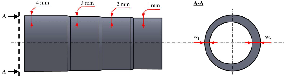 Fig. 3. Wall thickness reduction and tube eccentricity demonstrated on a sample of the DV test series.
3.2 Experimental design
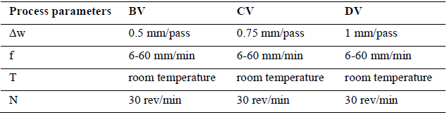
In this paper, the main focus is on identifying correlations between the process parameters of feed rate and the wall thickness reduction per pass and the resulting α’-martensite contents within the workpieces. The feed rates investigated were between f = 6 and 60 mm/min, with 6 mm/min steps in between. For the wall thickness reduction per pass, a range between Δw = 0.5 and 1.0 mm/pass was selected, with 0.25 mm/pass steps. Every preset wall thickness reduction per pass combined with the different feed rates resulted in three different series of tests: BV (ΔwBV = 0.5 mm/pass, f = 6-60 mm/min), CV (ΔwCV = 0.75 mm/pass, f = 6-60 mm/min) and DV (ΔwDV = 1 mm/pass, f = 6-60 mm/min). Each test series consists of ten experiments (one experiment per feed rate combined with the preset wall thickness reduction). Each experiment leads to one specimen. This means that BV, CV and DV imply separate test series, which differ by varying process parameters. The starting tubes do not differ across the test series except for the initial lengths, which is addressed in chapter 3.3. The temperature at which all the forming processes occurred was kept constant at T = room temperature. To exclude the influence and effects of the spindle rotation speed, this parameter was also kept constant at N = 30 rev/min. Table 1 summarizes the test parameters.
Table 1. Process parameters for the experimental investigations.
3.3 Process strategy
The forming strategy depends on the test series. As described, the necessary number of passes varies with different presets for the wall thickness reduction per pass. In total, the 4 mm wall thickness of all the tubes was reduced up to 1 mm, leading to the maximum total wall thickness reduction of Δwtmax = 3 mm. To provide sufficient space for the following micromagnetic investigations, the widths of the forming zones had to be at least 40 mm. The initial tube lengths were between 𝑙0 = 210 and 230 mm. As a result, for the BV test series, the number of forming zones had to be divided between two tubes. Fig. 4 shows the tubes after the forming process with the number of passes required for the forming zones, indexed by roman numerals, zero being the initial state.
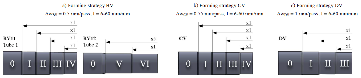 Fig. 4. Forming strategies for the different test series.
The process strategy includes the forming strategy and tool paths, illustrated for test series DV by way of example in Fig. 5. To simplify the illustration, only one of the three existing rollers is shown. The red arrows show the roller’s direction of motion. The DV test series includes three passes, each of which is illustrated with two images. The green lines in Fig. 5 indicate the initial length of the tube. It can be seen that the material flows against the axial motion direction of the rollers and causes tube elongation of Δ𝑙.
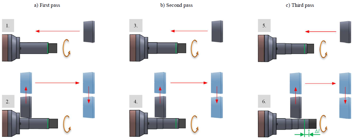
Fig. 5. Process strategy for the DV test series.
3.4 Measuring methods
In addition to the wall thickness measurements, two kinds of magnetic tests were performed close to the outer surface of the specimens. The Feritscope FMP 30 from Helmut Fischer measures the content of strain-induced α'-martensite by the magnetic induction method [24]. This sensor works in contact with the specimen and under static conditions and cannot therefore be used in closed-loop control systems. Micromagnetic testing with the 3MA-II device by Fraunhofer IZFP (Fig. 6b), by contrast, permits measurements without specimen contact under dynamic conditions, making it suitable for control systems. The α'-martensite content is not, however, measured directly by micromagnetic analysis.
Micromagnetic analysis is based on the magnetic Barkhausen noise (MBN) effect, described by means of the hysteresis loop in Fig. 6a. During magnetization, the walls that divide the magnetic domains within the material move in response to the applied field. This motion has a discontinuous character, due to the interaction of the walls with lattice defects, dislocations, phase changes, grain boundaries, precipitations and stresses [26–28]. On the MBN curve (Fig. 6a), the maximum amplitude of the MBN profile (Mmax) is the parameter of interest. Previous investigations show correlations between Mmax and the α'-martensite content [29,30].
This study focuses on correlations in flow-formed specimens, involving different process parameters, to formulate models that regulate closed-loop control systems. In a first stage, the measurements with the 3MA-II device (Fig. 6b) were performed under static conditions, in contact with the flow-formed specimens (Fig. 6c). In the near future, these correlations must be extrapolated to the measurements obtained under dynamic conditions.
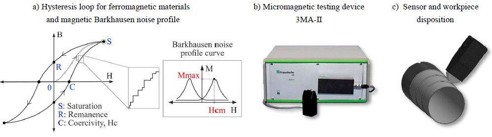 Fig. 6. Methodology of micromagnetic investigation.
4 Experimental Results and Discussion
4.1 Wall thickness reduction
The formed tubes in the BV, CV and DV test series with a varying number of forming zones were examined with regard to the wall thicknesses (Fig. 7). The yellow dot indicates the nominal wall thickness (w ideal) for each forming zone. In forming zone 0 the initial wall thicknesses deviate slightly from the ideal 4 mm. The deviation of the measured wall thicknesses grows with increasing feed rates. This can be observed for each forming zone and is probably caused by a smaller number of overrollings. This deviation rises as the total wall thickness reduction Δwt increases, due to the work hardening of the material. A direct comparison of the BV, CV and DV test series shows that the deviations tend to increase with larger wall thickness reductions per pass. This might be due to the smaller number of passes. In this way, the impact of effects such as material springing could be mitigated. Undesired deviations in wall thickness due to suboptimal workpiece or tool and machine behavior were to be expected. Effects such as elastic springback of the material and elastic tool behavior are known and will be detected in the near future by appropriate sensor application. This way, deviations of tool position and workpiece geometry will be monitored. Two co-travelling distance laser sensors will enable wall thickness measurement before and after the main forming zone. In addition, two stationary distance laser sensors will compensate for measurement errors caused by undesired deflection of the mandrel. The concept is described in Chapter 5.
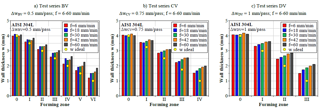 Fig. 7. Results of wall thickness reduction in flow formed specimens, produced with feed rates between 6 and 60 mm/min (12 mm/min steps).
For the following chapters, the degree of deformation in the radial direction, which is referred to as thickness strain φ, is used to present and compare the results. The negative values are given as absolute values. Here, only the wall thickness reduction starting from the initial wall thickness is of importance. Hence, forming in the tangential or axial direction is neglected.
4.2 Evolution of α’-martensite contents during flow forming with different process parameters
The measurements of α’-martensite by means of Feritscope FMP30 system were carried out close to the outer surface of the flow-formed components, up to a maximum depth of approx. 100 μm. As described in section 3.4, this system works with the magnetic-inductive measuring principle and the calculation of martensite content is based on the the investigations by Talonen et al. [24]. Fig. 8 shows a selection of results from the BV, CV and DV test series for a number of specimens. It indicates the resulting α’-martensite content in volume percent over the thickness strain as a function of the feed rate and reduction per pass. The α’-martensite content increases with higher thickness strain values, in agreement with measurements performed on stainless steel in [23,24]. Smaller feed rates lead to higher α’-martensite fractions, which tallies with investigations by Ferreira et al. [22] and Talonen et al. [31]. Moreover, a greater number of passes with smaller reductions per pass also promotes phase transformation. Both effects induce greater slopes of the curves, causing a saturation at smaller strains. This trend holds for all test series.
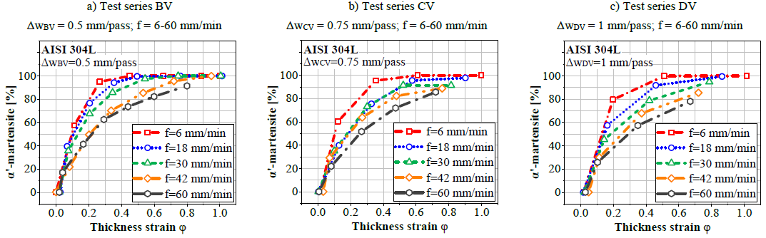 Fig. 8. Results of α’-martensite contents (vol.-%) for different strain conditions of flow formed specimens, with feed rates between 6 and 60 mm/min.
Fig. 9a shows a direct comparison of curves from BV and DV, illustrating the possible process window for α’-martensite content. Its value differs by up to 40 % for thickness strains of 0.2 and by 10 % for thickness strains of 0.8. For example, for BV (Δw = 0.5 mm/pass) and a feed rate of 6 mm/min, fully α’-martensitic microstructure occurs at 0.45 strain already, while for DV (Δw = 1.0 mm/pass) and a feed rate of 30 mm/min, phase transformation was not complete at up to a strain of 0.8. Fig. 9b illustrates the α’-martensite content over the feed rate and thickness strain for test series CV (Δw = 0.75 mm/pass) as a cubic interpolated surface, with the red dots indicating measurement values.
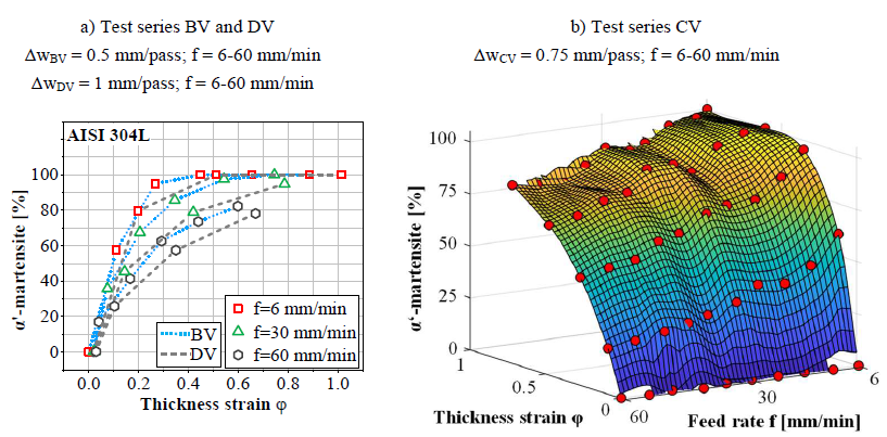 Fig. 9. Results of α’-martensite content over thickness strain as a function of reduction per pass and feed rate.
4.3 Correlation of α’-martensite contents measured with Feritscope and micromagnetic testing
Micromagnetic parameters are intended to be used within the softsensor concept in order to develop a model for the property-controlled specimen production. Correlations are thus required between these parameters and the α'-martensite measurements. The evolution of α'-martensite was characterized by means of micromagnetic investigations, using a 3MA-II device, to measure the magnetic Barkhausen noises (MBN). The maximum amplitude of the MBN curve Mmax is sensitive to the transformation from the paramagnetic austenite to the ferromagnetic α'-martensite. As illustrated in Fig. 10, Mmax increases with higher α'-martensite contents. These results agree with the investigation performed by Gorkunov et al. [25]. In Fig. 10, the saturation of α'-martensite for specimens produced at lower feed rates is evidenced. There is no clear influence of the thickness reduction per pass in the micromagnetic measurements.
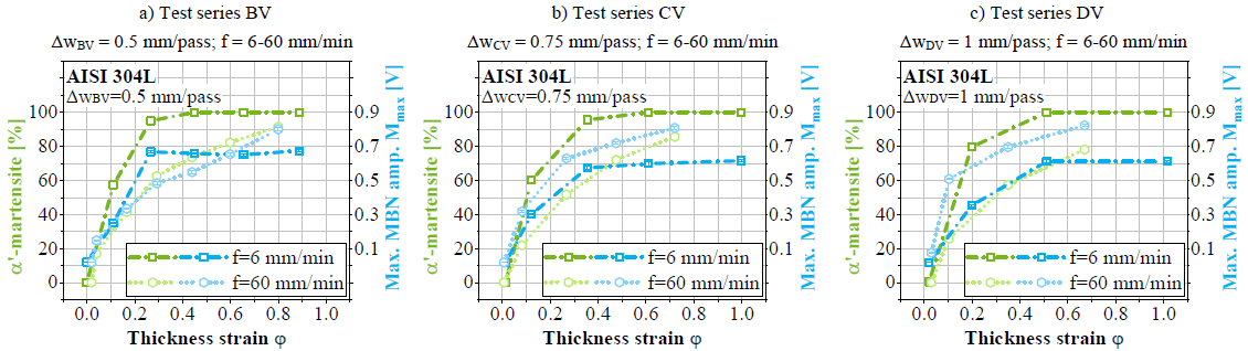 Fig. 10. Results of α'-martensite content correlated with maximum amplitude of Barkhausen noises Mmax for different strain conditions of flow formed specimens, produced with feed rates between 6 and 60 mm/min.
In Fig. 10, higher contents of α'-martensite are measured in specimens produced at lower feed rates. In addition, the increment of Mmax corresponds to higher α'-martensite values. However, the behavior of Mmax contradicts this idea. For the same thickness strain, the values of Mmax for specimens produced at 60 mm/min are above the values produced at 6 mm/min. The reason is that the micromagnetic measurements are influenced by strain hardening, phase transformation, surface damage and residual stresses. In this case, the Mmax measurements contain the effects of strain hardening, phase transformation and surface damage. It has been proved that Mmax increases with the surface damage [30,32]. Surface damage, characterized by roughness, is higher in specimens produced at 60 mm/min (Rz = 11.76 μm), while at 6 mm/min (Rz = 2.39 μm) the surface quality improves. This effect produces an attenuation of the Mmax measurements performed on specimens produced at lower feed rates. Fig. 11 summarizes the correlation between the α’-martensite content and the Mmax value. For the same α’-martensite content, the Mmax values decrease with lower feed rates due to the effect of the surface quality.
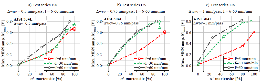 Fig. 11. Results of α'-martensite content correlated with maximum amplitude of Barkhausen noises Mmax for different strain conditions of flow formed specimens, produced with feed rates between 6 and 60 mm/min.
5 Conclusions and Outlook
The experimental investigations prove a direct correlation between the process parameters of feed rate and wall thickness reduction per pass for the resulting wall thickness accuracy as well as the α’-martensite content. It has been shown that higher accuracies and α’-martensite contents are achieved at lower feed rates. The same effect is evidenced for smaller wall thickness reduction steps.
Usually, process strategies for flow-forming aim to achieve a desired product geometry while accepting the resulting microstructure ‘as it is’. Considering the current wall thickness reduction per pass and the feed rate as actuating variables, it is intended to establish a closed-loop control to ensure geometrical accuracy as well as the desired material properties. This makes it possible to add novel characteristics to flow-forming products, e.g. an axially graded microstructure.
Geometry control is proposed to ensure the desired wall thickness reduction. By way of feedback, two laser distance sensors will be placed right in front and behind the main forming zone, axially moving along with the roller. The difference between the two signals yields the current thickness reduction. To compensate for measurement errors caused by undesired displacement of the mandrel and the workpiece during operation, two additional laser sensors, pointing to the tip of the mandrel, measure its position. The geometry controller then adjusts the rollers’ positions or feed rate based on the feedback signal.

Fig. 12. Model based control loop.
In order to ensure a desired α’-martensite content, an additional material property control is proposed. Since the α’-martensite content is not accessible to direct measurement, the 3MA-II measuring device determines the maximum magnetic Barkhausen noise amplitude, which is proven to be correlated with the α’-martensite fraction. The softsensor calculates its value, providing a property feedback loop. Both the controller and the softsensor rely on the correlation model based on data presented in this paper and adding up to form the model-based control scheme illustrated in Fig. 12.
The clear separation of the effects and mechanisms influencing the magnetic Barkhausen noise amplitude will be the scope of future work. Current work is focused on installing the sensors to form a closed loop and thus providing the basis for the control scheme.
Acknowledgements
The authors would like to thank the German Research Foundation (Deutsche Forschungsgemeinschaft, DFG) for supporting this project “Property control during spinning of metastable austenites” within Priority Programme SPP 2183 “Property controlled deformation processes”.
