1 Introduction
Bending is a widely used technique in the metal industry to form a desired shape in a flat metal surface and it comprises a large group of different methods. For the most common and elementary bending methods, research has already been substantially conducted. However, for more complicated bending processes where the number of distinct contact points changes in time, the existing literature is limited. Above all, the focus of these studies are generally on springback [1] to predict the final form. Literature that investigates the whole multi-point bending process are rare and specialized for one specific process [2].
In multi-point bending processes, four types may be defined depending on the freedom of movement of the dies [3]. The present paper discusses the bending of corrugated sheet. In this process the dies are all relatively fixed, i.e. the punches heights are set before forming, and thus the process belongs to the multi-point die group. Furthermore, multi-point bending allows three-dimensional surfaces to be formed, but for many products the process can also be viewed as forming a two-dimensional profile, in the case where no deformation occurs in the third spatial dimension. The applications of such corrugated sheets are extensive, e.g. the sheets are employed as moulds in the fibre cement industry. For this application, the dimensions of the final product must have sub millimetre precision, justifying the need for intensive and innovative research.
The development and use of an analytic model to predict the behaviour of a multi-point bending process has a number of advantages, namely that such models are less time-consuming than finite element models without an excessive loss in accuracy and they do not require an expensive experimental database as is necessary when building regression models. Next to this, in an analytic model, all of the parameters have a direct physical meaning, which provides useful insight into factors affecting the process, and allowing rapid extension to variants of dies layouts.
The model presented here is based upon recent research of air bending processes. In addition, with the multi-breakage effect present in large-radius bending, the loading scheme changes during the process. This multi-breakage phenomenon occurs when the contact area between a large radius punch and the plate is split in two zones and the force distribution on the plate evolves [4,5]. Vorkov et al. have investigated this phenomenon with experiments and regression models [6,7], finite element models [8] as well as with the construction of an analytic model with circular approximation [9,10].
As the latter in [9] only provides the internal bending moment and the bending force at the end of bending, a similar, but more accurate internal bending moment calculation will be performed. More specifically, the model of Wang et al. [11] will be utilized.
The specific multi-point bending process case of corrugated sheets, considered in this paper, is the industrial process where a wave pattern is bend into a sheet by pressing each wavelength in different bending steps as depicted in Fig. 1. The plate is first precisely positioned under the press (a) and one wavelength is pressed (b) by moving the punch (ram) down until the plate is completely pressed between the dies (c). After retraction of the punch, the springback brings the wave to its final form (d). Next, the sheet is accurately repositioned to form the next and equal wavelength and the procedure is repeated until the whole sheet is pressed.
During each bending step, several states can be identified regarding the amount of contact points. At first, the plate touches the dies at three points (at the convex die parts). While the punch is moving down, the plate makes contact at more points until it has eight contact points with the tooling. At the stopping position, the sheet is completely squeezed between the upper and lower dies.
Three phases are distinguished: the first phase is when the sheet is only in contact with the middle upper die, the second phase when the sheet also touches one of the upper outer die parts and the third phase where the sheet contacts all three upper die parts. Each shift to the next phase corresponds with an extra pressing force from the punch interacting with the plate.
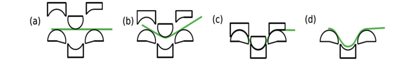
Fig. 1. Different bending stages
2 Model Composition
The main objectives of the proposed analytic model are to predict i) the evolution of the bending forces during bending and ii) the final shape of the sheet after springback. Starting from the known geometry of the problem, the coordinates of the contact points are identified, considering the multi-breakage phenomenon. Based on the geometry, the internal bending moment at the contact points is determined. The bending force can then be calculated from the force and moment equilibria. The springback can in a final step be calculated based on the bending moment.
The presented analytic model of such a wave bending process is supported on following assumptions:
-
No variation in the forces and the shape along the bend axis is assumed (plane strain assumption).
-
The elastoplastic stress-strain relationship is expressed with a combination of Hooke’s law and the Swift equation (1) for the isotropic strain hardening. The Young’s modulus for plane strain is given in (2) with 𝜈 the Poisson’s ratio.

The Bauschinger effect is neglected.
-
The friction forces are modelled with a simple Coulomb model:

Furthermore, the sheet is assumed to not move over the middle die.
-
With the circular approximation of the large-radius bending, it is assumed that the plate perfectly wraps around the dies between the contact points. The forces however will only act at the contact points. In reality, a gap will be present between die and sheet.
-
The curvature of the neutral line for thin plates can be approximated to the radius R of the dies plus half the thickness t. In reality, the neutral line doesn’t coincide with the middle of the plate.
-
No correlation between the bending steps are assumed. The previous bending step of the plate is assumed to have no effect on the current bending step. Furthermore, the model is constructed for the first wave, but the model is easily adopted to the bending of the middle or last wavelengths of the plate.
-
No thickness reduction of the sheet is present in the process.
-
The process is considered to be quasi-static, i.e. the time-derivatives are neglected and thus a zero acceleration is assumed.
-
Lastly, the influence of gravity is neglected as this force is minor to the other forces in the process.
2.1 Geometric model
As the problem is completely prescribed by the geometry and the position of the tools, i.e. the die dimensions and the position of the ram are known, all the remaining necessary geometrical dimensions of the sheet can be calculated. In Fig. 2, the constants, parameters and the bending angles used in the analytic model are depicted.
With the circular approximation, the plate is assumed to always be tangential to the convex dies. As a result, the bending angle 𝛾 can be calculated from the bending depth y:

and the length lb of the plate part between the contact points can be found:

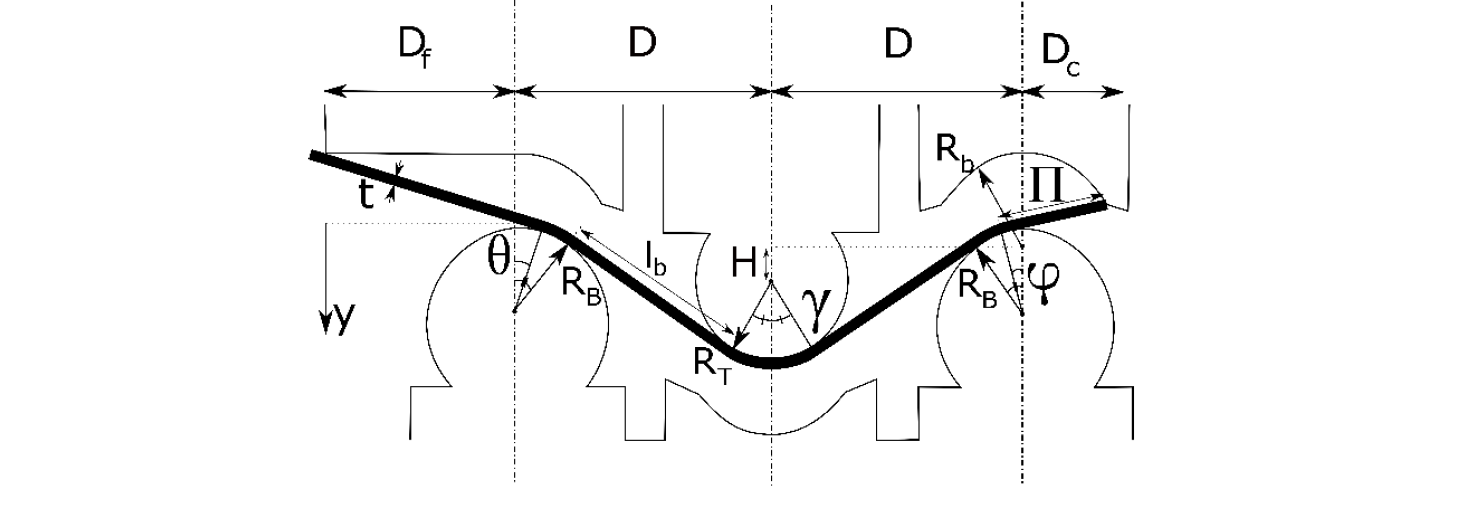 Fig. 2. Constants, parameters and bending angles.
Furthermore, the moment of transition to the next phase can be identified by finding the bending angle (or depth) where the plate makes contact with the upper outer dies. For the right side, this is achieved by solving the system of equations (4), (6) and (7).

with 𝜅 the angle with the vertical of the contact point on the concave upper die. The equation of the bending angle where the plate makes contact with the upper die at the left side is:

In the second and third phase of the process, the bending angles 𝜃 and 𝜑 can be obtained by substituting 𝛾 with the respective bending angle in equations (8) and (6-7).
2.2 Internal bending moment model
To find the forces interacting in the process, the bending moment in the contact points have to be calculated first. The stress distribution across the sheet thickness is illustrated in Fig. 3. The distance tel from the neutral line where the plastic yielding begins, is the point where plasticity start to occur as determined by the Swift law.

The internal bending moment is then found as the superposition of the elastic bending moment and the plastic moment [11]:

with w the width of the plate. Substituting the respective laws and considering a plane-strain deformation for isotropic materials, gives:


Fig. 3. Schematic representation of the stress distribution in the material. The dashed line is the neutral line.
2.3 Model regarding Force
With the internal bending moments at the contact points and the distances between the contact points known, all the forces of the process can be found by solving the system of equations of the moment equilibrium at the contact points A to F and the equilibrium of forces.

with MY the internal bending moment of contact point Y (A-F) and 𝐿⃗𝑋𝑌 the location vector from contact point Y to the point of interaction of force 𝐹⃗𝑋.
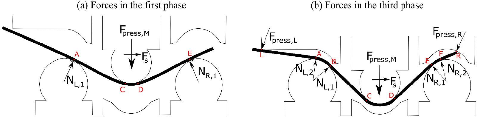
Fig. 4. Forces present in the process. The friction forces are not depicted for clarity of the diagram.
All the forces interacting in the system (except friction forces) are illustrated in Fig. 4. Depending on the position of the press ram and thus the current phase, the forces are represented by (a), (b) or a combination of both (second phase). For example, equation (14) for point C in the first phase becomes (Fig. 4a):

and for point B in the third phase (Fig. 4b):

2.4 Springback
Springback is a widely investigated phenomenon in metal forming as it is present in all forming processes. For three-point air bending, the springback is defined as an angle increase ∆𝛽 of a workpiece. For a wave bend, this measure applies to multiple circular bends as shown in Fig. 5. Applying the principles of the circular approximation [9], for a wave bending process the moment distribution at the end of the bending process can be approximated by a piecewise linear function.
The formula for the incremental springback angle is described as:

with M the moment, I the second area moment and s the arc length, which can easily be found due to the simplified circular approximation. Integrating the formula from a certain reference point gives the desired springback angle increase from that point:

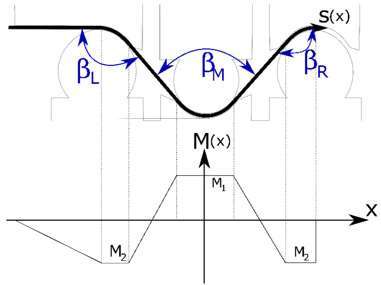
Fig. 5. The parameters of springback (blue) and the approximate moment distribution at the end of bending.
3 Finite element simulation & video processing
3.1 Finite element model
To validate the analytic function, the bending force and springback output is compared with a finite element (FE) model (Fig. 6).
The finite element model is implemented in the commercial package Abaqus. This software is used to solve the evolution equations (differential equations) for a complex geometry with known material properties. The mesh of the model consists of 2000 2D plane strain second order quadrilateral elements with 3 elements through the thickness. This has been found to sufficiently account for the through thickness strain distribution. Output of the simulations are strains, stresses, displacements, and forces throughout the entire process.
In the FE model, the total strain rate is modelled as an additive sum of the elastic and plastic strain rates analogous to the analytic model. The elastic strain is related to the stress by a generalized Hooke law. The material is assumed to be isotropic. Plasticity is considered to be rate independent with a Prandtl-Reuss flow rule in combination with a von Mises Hill criterion [12] and isotropic work hardening is used, with a Swift law (see above).
The FE model is built such that the sheet can be positioned and the ram movement in time can be chosen exactly as in the industrial process. The tooling is assumed to be perfectly rigid and contact modelling (with a Lagrangian penalty method) with the same coulomb model as previously mentioned is used.
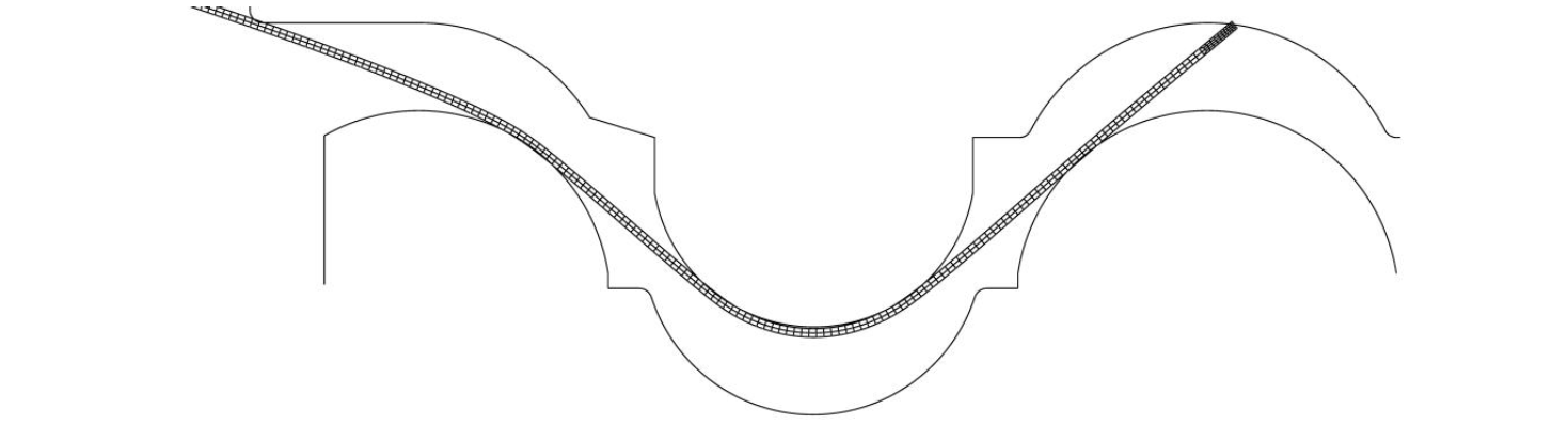
Fig. 6. Screenshot of the finite element simulation.
3.2 Process parameters
The material used in both the analytical as in the FE models has a Young’s modulus of 200GPa and a Poisson’s ratio of 0.3. The Swift parameters for the work hardening characteristics are K=750MPa, 𝜀0 =0.02 and n=0.2 and the Coulomb dynamic (and static) friction coefficient is 0.11 (resp. 0.39). The 2D FE simulations have been done for sheets with a thickness of 2mm and a width of 1000mm. The industrial process is filmed with a Sony HDR-PJ620 video camera.
4 Results and discussion
4.1 Bending force
In Fig. 7, the calculated bending force as a function of the bending depth from the analytic model and the FE model is shown. From the stepwise rise in total bending force calculated with the analytic model, the different phases in the bending process can clearly be distinguished. This is likely because of the assumption that the multi-breakage phenomenon occurs at all three convex dies at any instance. In reality, the sheet will first have elastic behaviour and will thus have a curvature larger than the die radii. Only when the bending continues and the curvature becomes smaller than the die radius, the multi-breakage effect is present. As a result, the FE bending force shows a more smooth and more accurate increase in force. In addition, the analytic model starts with a non-zero force at zero displacement due to the circular approximation. Overall, the analytic model presents the same trends as the FE model.
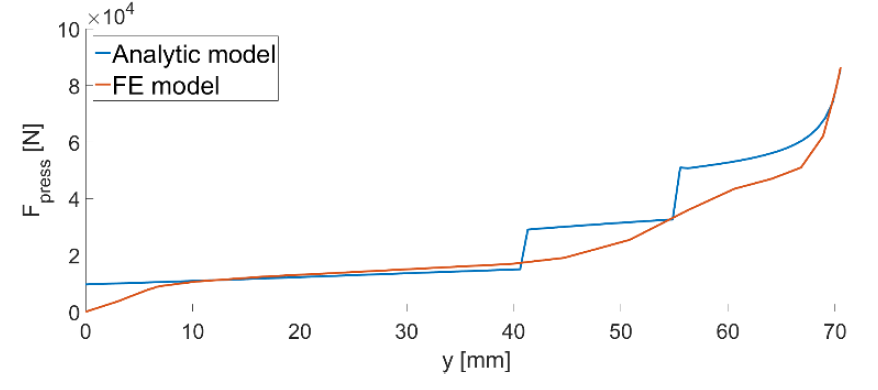
Fig. 7. The total bending force as a function of the bending depth from the analytic model and the finite element model.
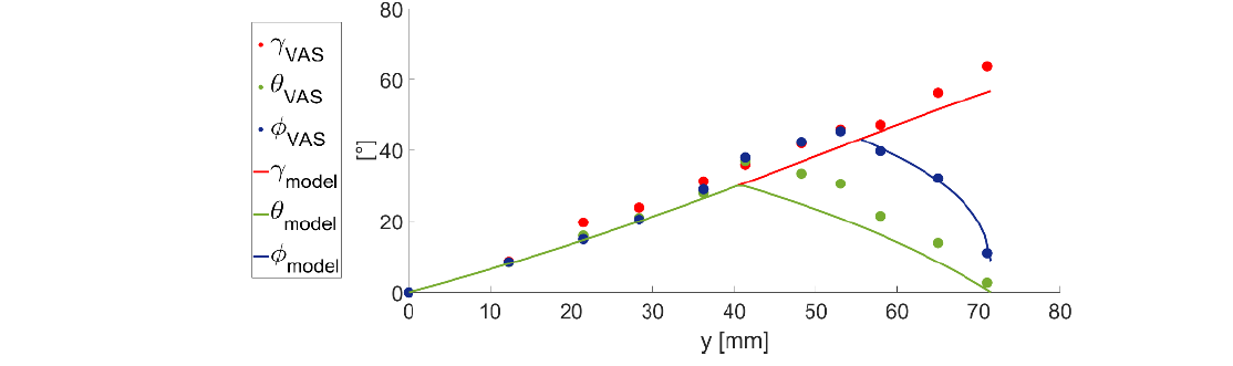
Fig. 8. The bending angles as a function of the bending depth retrieved from the video analysis (VAS) and from the analytic model.
4.2 Bending angles
The bending angles as a function of the bending depth obtained from the video analysis of the industrial process and the analytic model are depicted in Fig. 8. The measurement of the angles with the video processing has limitations: a gap in the third dimension between the tooling ends and the plate end and the horizontal alignment of the footage lying on the top of the bottom dies. The retrieved angles from the video analysis have thus a certain bias from the real angles, but the general trends are clear: 𝛾, 𝜃 and 𝜑 steadily increases with the bending depth until the second phase starts and 𝜃 begins to decrease to zero. When the third phase begins, 𝜑 also gradually diminishes to zero. Comparing the measured angles with the angles from the analytic model shows that the angles of the model roughly coincides with the course of the angles of the video analysis.
4.3 Springback
The difference in angles before and after springback for the analytic model and the finite element model are captured in Table 1. The springback of the central bend is higher than the left bend since at maximum bending depth the central bend is a more severe bend than the right bend. The small difference between the analytic and the finite element model for both the springback angles demonstrates that the developed analytic model can roughly predict the springback of the wave bending process.
Table 1. Springback properties.

5 Conclusions
In this paper, an analytic model for industrial wave bending with large radius dies was proposed that enables the user to predict the bending dynamics and the springback of the process. By comparing the analytic model with a more expensive finite element model, it is shown that the analytic model gives accurate results for both the process dynamics as the springback. Before being industrially applicable in process design, experimental verification of the force and springback is necessary.
Acknowledgements
This research is supported by a Baekeland Mandate (HBC.2594) from the Flanders Innovation & Entrepreneurship (VLAIO) and the company OptiQuench.
