1 Introduction
The reinforcement of concrete by steel fiber mainly increases the dissipated energy until total separation [1] and thus improves the post-failure behavior of the building material. Depending on the filling quantity, an increasing tensile and compression strength is also possible [2]. Steel fiber reinforced concrete exhibits a higher versatility compared to conventional reinforced concrete and can be directly added to sprayed concrete. As one of many examples of its applications, the use of steel fibers together with further add-ons allows the improvement of so-called Ultra High Performance Concrete (UHPC) [3]. The increasing strengths result in reduction of the layer thickness and contribute to the reduction of concrete masses [3] and of the release of greenhouse gases.
To exploit the potential of the reinforcement through steel fibers, an ecologically and economically efficient production method of the additive is required. The conventional procedure by wire drawing does not meet these requests due to a low flow rate and high energetic effort. Stahl patented an alternative production procedure by notch rolling and cyclic bending in 2010 [4]. During notch rolling, a wire strip is manufactured by imaging the rolls’ indentations negatively on both sides of the metal strip. The material in the region of the notches fatigues during the cyclic bending load, which is realized through a fulling process, until there is no more cohesion. A general layout of the process is given by Biallas and Merklein in [5]. The authors derive two general process methods: producing wires along or perpendicular to the rolling direction. They emphasize the need for further analysis of the process through experimental and simulative trials for evaluating the suitability determining the process parameters. For numerical implementation of the process chain for the test steel DP600 with a thickness t0=0.8 mm, they determine material models for both process steps based on several characterization tests. The paper at hand supplements the study by extending the derived material model of the second process step by a validation of the derived kinematic hardening parameters via a cyclic bending test and the consideration of a ductile damage criterion. To enable a test phase of the cyclic bending process and thus a validation of the numerical model, the production of wire strip with comparable characteristics to the notch rolling process is desired. To meet this intention, a stamping process is designed and evaluated regarding the expenditure of force and the geometrical properties.
2 Material Behavior under Cyclic Bending Load
The exact layout of the process parameters of the fulling procedure requires a comprehensive understanding and modelling of material behavior under cyclic bending load. In the following, the kinematic hardening and ductile damage behavior of a DP600 sheet metal (t0=0.8 mm) shall be evaluated through experiments. Based on this, the parameters of an isotropic-kinematic hardening model are validated and ductile damage parameters are derived. They are to be used for numerical implementation of the second process step. This work presents the execution and evaluation of tests in rolling direction (RD), the procedure for tests in transverse direction (TD) is to be performed analogously.
2.1 Kinematic Hardening
The fulling process causes a cyclic tension-compression load on the initiated notches. During such loading, specific metals exhibit the Bauschinger-effect [6] characterized by early yielding and a distinctive transient area after load reversal. For evaluating and modelling the hardening behavior during cyclic bending, tension-compression tests were presented in [5]. Table 1 lists the parameters of the determined isotropic-kinematic hardening model for RD specimens that are to be validated.
Table 1. Material settings of DP600 (t0=0.8 mm, RD) for modelling isotropic kinematic hardening with two back-stress terms [5].
![Table 1. Material settings of DP600 (t0=0.8 mm, RD) for modelling isotropic kinematic hardening with two back-stress terms [5].](docannexe/image/3826/img-1.png)
A process-oriented validation of the model by an experimental and numerical cyclic-bending test (CBT) developed by Merklein et al. [9] is performed. The experimental set-up is pictured in Fig. 1a. A rectangular specimen is clamped on both exterior sides and in the middle. The clamp set in the middle can move vertically (stroke s) by applying a stamp force F. The outer clamp sets with an initial distance d0 of 20 mm follow the movement horizontally. These kinematic relations allow a pure bending load along the radii r. The validation procedure seems especially purposeful since the caused stress state is similar to during the fulling process.
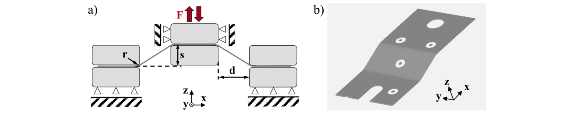
Fig. 1. Cyclic bending test (CBT). (a) Principal sketch of the kinematic relations. (b) Surface model of half of a specimen by ATOS (GOM, Braunschweig).
The load sequence follows the procedure of moving up to the maximum position smax=10 mm, going down to s=0 mm and moving up to smax again, so that two load reversals result. After the execution, half of the specimens’ geometries are captured by the three-dimensional optical measurement system ATOS (GOM, Braunschweig), as shown in Fig. 1b. The force-stroke curves are averaged to minimize the impact of scattering. The resulting course is given in Fig. 2a.
For validation, the CBT is mapped numerically in the simulation software LS-DYNA. For reasons of symmetry, only quarter of the set-up is modelled. The sheet is meshed by fully integrated shell elements with an edge length of 0.8 mm. The anisotropic yielding of the sheet metal is modelled via the Barlat 89 yield criterion [10] reduced to Hill 48 [11]. Subsequently to the explicit CBT simulation, an implicit spring-back simulation is performed. Fig. 2a and b present the resulting force-stroke curve and geometry after spring-back. In addition, results of a simulation modelling only isotropic hardening are considered to allow evaluation. Fig. 2a underlines that the use of isotropic-kinematic hardening models reaches a higher prediction quality of the force course than purely isotropic hardening. The RMSE can almost be halved. The error of the isotropic model must be evaluated even higher for a greater number of load changes. The simulation considering isotropic-kinematic hardening succeeds to picture the characteristics of the Bauschinger effect and shows a smooth transient area. It is assumed that the remaining deviations result from the isotropic hardening parameters since the already occur during the first loading. The analysis of spring-back behavior, which is presented in Fig. 2b, states that the prediction of the specimen’s geometry is satisfying for both simulation models. However, they both overestimate the resulting height.
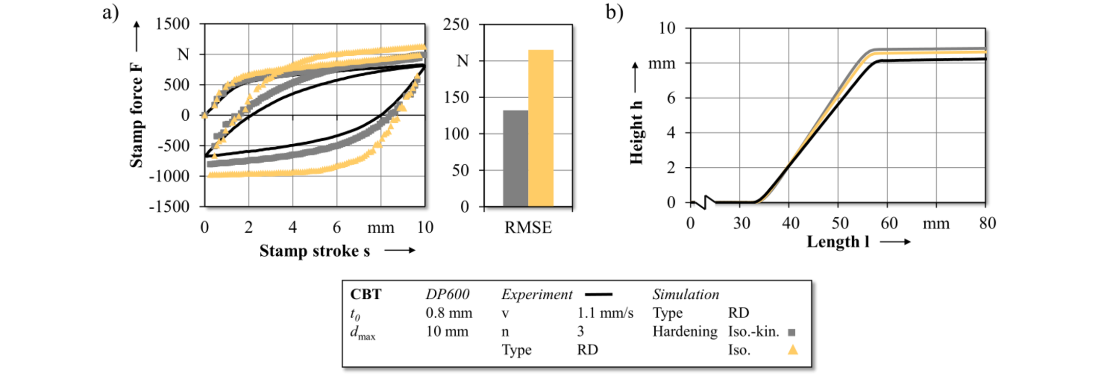
Fig. 2. Experimental and numerical results of the cyclic bending tests (CBT). (a) Numerical force-stroke curve compared to experimental course in RD. (b) Spring-back geometry of simulations and experiment.
2.2 Ductile Damage
Cyclic bending of the notched sheet results in ductile fracture. Its developing is dependent on the nucleation, growth and coalescence of voids, which occur primarily at the ferrite-martensite interfaces of a dual-phase steel [12]. Tekkaya et al. [13] proved that material damage detected through the existence of voids is mainly responsible for differences in fatigue strength. Thus, it is indispensable to include ductile damage modelling for the considered process. Two types of ductile damage models exist: macromechanical and micromechanical. Macromechanical models consider damage development in a purely empirical way. For modeling the above-described void mechanisms that are responsible for the development of macro cracks, micromechanical integration models were developed [14] that are less process-bound than macromechanical models. Continuum damage mechanics (CDM) models represent a further improvement and succeed to map the physical processes in the material [15] and to model interaction with mechanical material behavior [14]. The Lemaitre model [16] represents a model that predicts ductile damage satisfactorily and whose parameters can be determined relatively easy [14]. As shown in equation (1) [17], Lemaitre refers the equivalent stress σνm on the effectively resisting cross section derived through the damage variable D to determine the effective stress σ̅. The definition of the damage rate is given subsequently. The damage energy density release rate Y is given in equation (2) [17]. D shows a linear course starting from the damage threshold εpeff,d with a slope dependent on the damage energy release rate S until reaching the critical damage value Dc. ν represents the Poisson’s ratio, E the Young’s modulus, σH for hydrostatic stress.


The Lemaitre model will be used to model ductile damage of the test steel. The parameter determination is performed inversely on a global base by adjusting the simulative force-elongation curve of a tensile test model in LS-DYNA to a corresponding experimental curve. The curve matching method in LS-OPT by reducing the mean square error using the ASA algorithm is applied. The experimental data is derived from the optical strain measurements of the tensile tests [5] according to EN ISO 6892-1 [18]. Fig. 3 presents the simulation set up. The fully integrated shell elements’ size within the measuring distance is 0.5 mm. The application of a symmetry plane reduces the computing time. The elongation is measured by the displacement of two nodes with an initial distance equal to the optical extensometer distance (80 mm). The force is extracted from a cross-sectional set.
The material model MAT 104 [17] is chosen for representing the relevant material behavior. Due to low impact of anisotropy [15], isotropic yielding is assumed. For defining isotropic hardening, the Hockett-Sherby-approximated true-stress-true-strain curve of the experimental tensile test [5] is applied. Table 2 specifies the remaining material data. The critical damage value Dc of the Lemaitre damage model is set to a constant value of 0.3 [15]. The parameters 𝑆 and εpeff,d (bold type in the table) are adapted within the LS-OPT procedure. The starting value (sv) of εpeff,d is equal to the uniform elongation eu, since damage initiation is assumed when necking starts. The permitted values are limited to a range of approx. 5 % less or more than eu. The sv of S is set to 15 and the permitted values are limited from 1 to 30 [15]. The resulting optimum values of the parameters are also given in Table 2. Fig. 4 plots the resulting force-displacement curve of the simulation and the experiment. The model succeeds to predict the failure of the material satisfactorily. However, the material softening after passing eu cannot be mapped by the simulation considering the determined Lemaitre damage parameters.
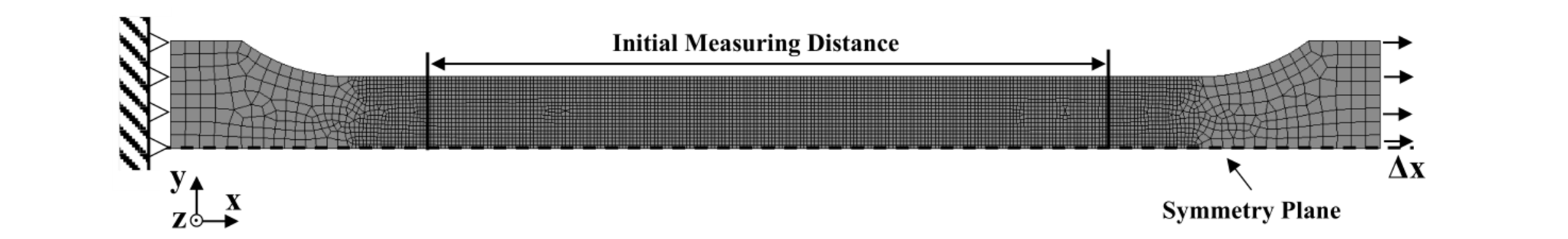
Fig. 3. Simulation set up of the uniaxial tensile test in LS-DYNA.
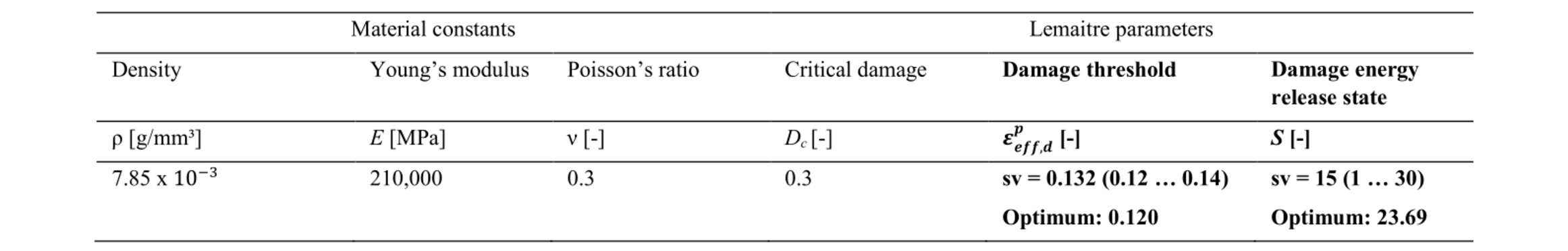
Table 2. Material settings of DP600 (t0=0.8 mm) for simulation model of tensile test in LS-DYNA. sv = starting value.
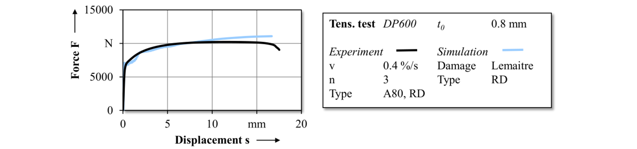
Fig. 4. Experimental and simulative force-displacement curve of the uniaxial tensile test for ductile damage parameter determination.
3 Design and Trial of a Model Process for the Notch Rolling
For validation of the determined material models, experimental reference is required. For a first approximation of the process implementation, a model process representing the notch initiation is determined, which is essential for a subsequent analysis of the cyclic bending behavior. Its application will enable a first validation of the numerical model and ensures the availability of wire strip for a evaluation of the cyclic bending procedure. As simplification, it is chosen to omit the continuous rolling movement, which leads to a discontinuous stamping procedure. During notch rolling, material is displaced from the main forming zone to the surrounding areas in front and next to the notch. Such material pushing causes compressive stresses along and tensile stresses vertically to the material displacement direction. For relatively high thickness reduction, it is expected that the yield strength is exceeded in the ambient material [19]. For referring the results of the model process later on, it must be considered that the material pushing ahead of the roll cannot be pictured in the model process.
Stamping tools with seven tips arranged in the middle of the compression surface with a distance w=0.9 mm, a tip radius rn=0.01 mm and a notch angle β=90 ° are placed in a tool device of a universal testing machine (Schenck Trebel and Zwick, 400 kN) as shown in Fig. 5. A specimen of DP600 sheet metal (t0=0.8 mm) is placed in between the tool halves and is compressed until the tools reach a minimum distance d min to each other. Experiments with dmin set to 0.3 mm, 0.4 mm and 0.5 mm are performed for specimens taken from RD of the sheet metal. Each test is repeated three times. As result, the force-stroke curve is extracted and the resulting sheet thickness and web height in the indented region of the specimens are measured by a manual microscope. Fig. 6a shows the considered measurements. For validation of the material model determined in [5], the stamping is modelled numerically in the simulation software Simufact Forming V14.
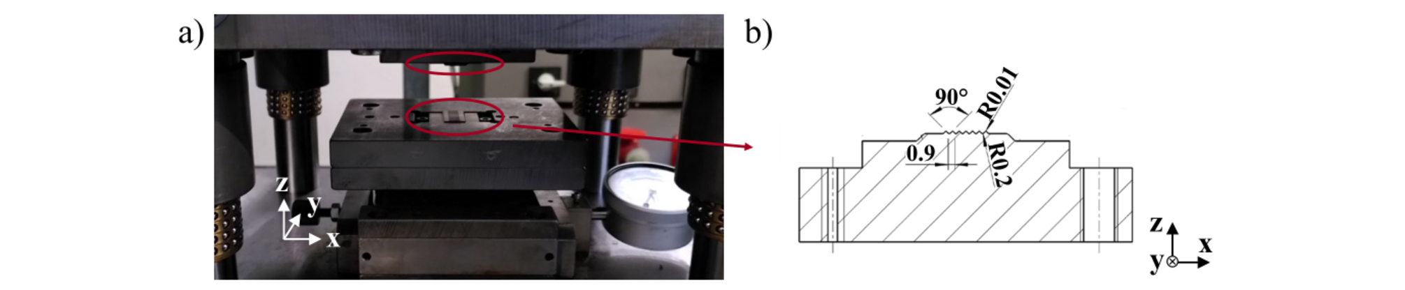
Fig. 5. Model process notch stamping. (a) Tool set up in the testing machine. (b) Cross-sectional view of one stamping tool.
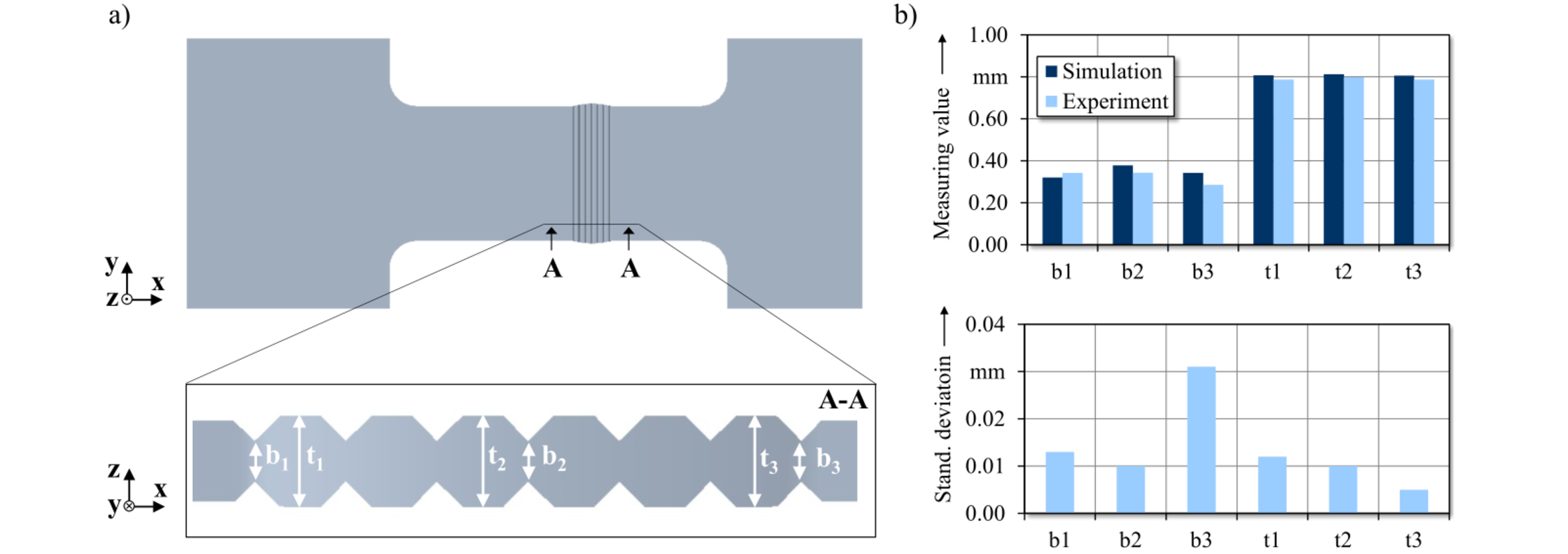
Fig. 6. Measuring of the notch stamping specimens. (a) Sketch of the specimen and definition of measurements. (b) Corresponding measuring values for a stamping test with dmin=0.3 mm in RD and the standard deviation.
Table 3. Maximum force values of the notch stamping process in experiment and simulation (RD).

Fig. 6b gives the averaged measuring results of the tests with dmin=0.3 mm as an example. The experimental thickness values show that no pronounced buckling occurs next to the indented regions. The sheet thickness is higher in the middle section and the notch in the middle is deeper than in the outer ranges. This is confirmed by the results of the further tests. It is assumed that slight tilting of the tools causes the differences of b1 and b3. Fig. 6a indicates that the specimen widens in notch direction. However, the deviating process sequence described above limits the suction capability with regard to elongation in continuous rolling.
The simulation model forecasts force rising to start a little later than in experiment, but the remaining smoothed force courses show similar behavior for dmin=0.4 mm and 0.5 mm and reach comparable Fmax as in experiment as presented in Table 3. The further course for modelling tests with dmin=0.3 mm clearly overestimates the experimental maximum force by 88 %. This is interpreted as an indication to check the extrapolation of the hardening law for validity. The analysis of the simulation measurement results allow the conclusion that the numerical model mostly overestimates the resulting web height, which might be caused by too high assumed elastic recovery. The variations in sheet thickness are minor.
4 Summary and Outlook
The application of steel fibers as concrete reinforcement promises a versatile construction material with improving strengths. To increase the productivity and to decrease the energy expenditure of the manufacturing procedure of steel wire fibers, the process chain notch rolling and cyclic bending is proposed. The extensive analysis of the production method requests the understanding and modelling of the material behavior. In addition to the material model suggestions derived in [5], the material model of the second process step is partly validated and extended. The isotropic-kinematic hardening model according to Chaboche-Rousselier is validated by applying a cyclic bending. Compared to a pure isotropic hardening model, the simulation applying isotropic- kinematic parameters succeeds to improve the mapping of the force-displacement curve. The deviations of the spring-back predictions of the simulations may be attributed to a diverging mapping of the isotropic hardening proportions and are to be reviewed by further analyses. As further supplement, the consideration of ductile damage is evaluated and the parameters of the Lemaitre damage model are derived inversely. The tensile test simulation considering the obtained parameter set pictures the material failure. The lack of modelling material softening can be also reasoned by diverging isotropic hardening models and will be part of future research. To allow first experimental implementation of the processes for validation of the derived material, a notch stamping process is designed and evaluated. It shows applicable data as a first evaluation of the material model for the notch rolling process. The derived wire strip will be used in further studies to allow implementation and validation of the cyclic bending process.
Acknowledgements
The authors wish to thank the German Research Foundation (DFG) for funding the corresponding research project 419390985 and SSAB for providing the applied DP600 steel samples.
