1 Introduction
A further reduction in fuel consumption and CO2 emissions in traffic can be achieved through lightweight design. This is resulting in an increasing proportion of high-strength steel and aluminium in car bodies. To join these materials, self-piercing riveting (SPR) is a well-established technique. By contrast to resistance spot welding, SPR turns out to be beneficial, due to its capability to join multi-material structures and its better joint properties [1]. The four stages of the SPR process are demonstrated in Fig. 1. Two or more sheets are clamped between a blank holder and a die. A punch presses a semi-tubular rivet into the sheets. The rivet pierces the sheet on the punch side before flaring in the sheet on the die side. This then creates an interlock [2].
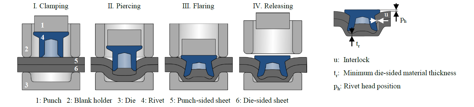
Fig. 1. SPR process stages and characteristic joint parameters in the cross-section of a severed joint according to [3]
Several methods can be used to inspect the quality of the resulting joint, especially in respect of its strength. The characteristic joint parameters as per [4] can be determined over the cross-section of the joint (see Fig. 1). These are an indicator of the expected joint strength. Standardised experimental tests or, as an alternative, numerical simulation are used for reliable determination of the joint strength [5]. For experimental examinations, specimens are tested destructively under defined load conditions using a testing machine. Parameters like maximum force, maximum displacement and energy adsorption until failure can then be determined on the basis of the measured force and displacement during the test. The failure mode can also be analysed. Typical failure patterns for self-piercing riveted joints, which are illustrated in Fig. 2, are known from [6] and [7]. With conventional rivets, whether the rivet foot is torn from the die-sided material or the rivet head is torn from the punch-sided sheet depends on the combination of the amount of interlock and the strength and thickness of the sheets. In general, a low strength in the punch-sided sheets results in the rivet head being torn from the punch-sided sheet and the emergence of a slot. Rivet fracture is promoted by brittle rivet materials. The rivet is essential for SPR. For this reason, it has been continuously improved in the past. A promising approach is the use of stainless steel with high strain hardening as the rivet material. This has certain advantages. Due to the corrosion resistance of the material, the coating is no longer required and, since sufficient material strength is achieved during forming, the heat treatment can be omitted. This shortens the manufacturing process. Because the strength of stainless steel is achieved by cold forming, systematic adjustment of the local strength is also possible. This offers the opportunity to improve the rivet’s deformation behaviour and hence increase the joint strength. Attempts to use stainless steel as rivet material have been published in [8] and [9]. The strength attained with the rivet materials used is not, however, adequate in respect of the requirements of modern sheet materials. High nitrogen steels, by contrast, provide excellent mechanical properties. Due to their high strain hardening, a strength comparable to the strength of common quenched and tempered rivet materials can be achieved. The main elements in the chemical composition of high nitrogen steel 1.3815 are N (0.76 m%), Mn (18.86 m%) and Cr (17.07 m%), whereas the most important elements in the common rivet material 38B2 are C (0.38 m%) and B (0.004 m%).
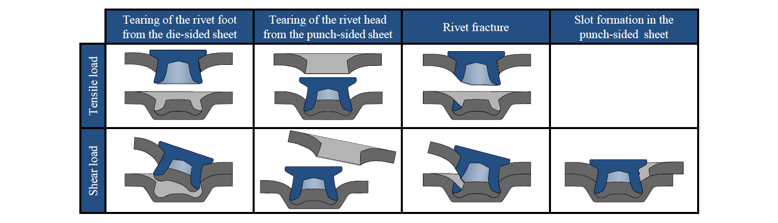
Fig. 2. Failure mode for self-piercing riveted joints
The focus of the present investigation is on the analysis and evaluation of the attainable strength of joints riveted by conventional rivets and rivets made of high nitrogen steel 1.3815. As in [3], the investigation is conducted for two challenging material combinations. Material combination 1 (MC 1) consists of high-strength steel HCT780X on both sides. Material combination 2 (MC 2) consists of aluminium EN AW-5083 on the punch side and HCT780X on the die side. All the sheets have a thickness of 1.5 mm. Experimental tests show the yield strength of steel HCT780X to be 565 MPa, with a tensile strength of 861 MPa at an elongation of 12.4 %. The yield strength of aluminium EN AW-5083 is 157 MPa and the tensile strength is 292 MPa at an elongation of 18 %. The steel sheets are galvanised, while the aluminium sheets are uncoated. Experimental sampling for both material combinations is carried out in [3]. For joining material combination 1, a rivet of type P and a flat die with a diameter of 8.4 mm and a depth of 2.0 mm are selected, while, for material combination 2, a rivet of type HD2 and a mandrel die with a diameter of 8.5 mm and a depth of 2.0 mm are selected. Both the selected rivets, the P-rivet and the HD2-rivet, are coated with Almac®. They are made of steel 38B2 and quenched and tempered to a hardness of 480 ± 30 HV10. Based on the properties of the selected rivets, as well as on the simulation-based analysis of the material flow and the stress and strain conditions within the rivet during the joining process, an improved rivet geometry permitting reliable joining of both material combinations with just a single rivet geometry is elaborated in [3]. The aim of the rivet design is to guarantee attainment of the required values for the characteristic joint parameters and a crack-free joint and to avoid any bending and compression of the rivet. In addition, manufacturability by cold forming and feedability to the riveting system using standard equipment are ensured. The rivet geometry of [3] is used as the target for elaborating a manufacturing concept for rivets in high nitrogen steel 1.3815 in [10]. A two-step concept is used for the cold forming process. The high strain hardening of the high nitrogen steel causes very high tool loads. The foot chamfer is thus increased from 60° to 70° compared to the target in [3] in order to reduce the stress prevailing in the tools. Due to the fact that the stress in the tools cannot be sufficiently reduced and that the tool materials used are already the most capable ones, it proved necessary to reduce the forming stroke.
2 Materials and Methods
As already mentioned, the investigation focusses on two challenging material combinations consisting of high-strength steel HCT780X and aluminium EN AW-5083 and on four different rivets. An overview of the rivets and their properties as well as a comparison of the cross-sections of the rivet geometries is given in Fig 3. The manufactured rivets made of high nitrogen steel 1.3815 deviate from the target of the cold forming process, especially in the area of the rivet head. The head diameter is much lower than intended because of the reduced forming stroke. An investigation concerning the rivet’s surface condition demonstrates that SPR regarding the joining process is possible without rivet coating [11]. Thus, the high nitrogen steel rivets are not coated. As the conventional rivets are heat-treated and thus the hardness is almost homogenous within the rivet, the hardness within the high nitrogen rivet results from the strain hardening during the forming process. Because of the high strain within the rivet head, the hardness is higher than the hardness within the rivets made of treatable steel in the same area. Nevertheless, before joining, the hardness within the rivet foot is lower. The deformation behaviour during the joining process and the change in hardness during the process are examined in [12].
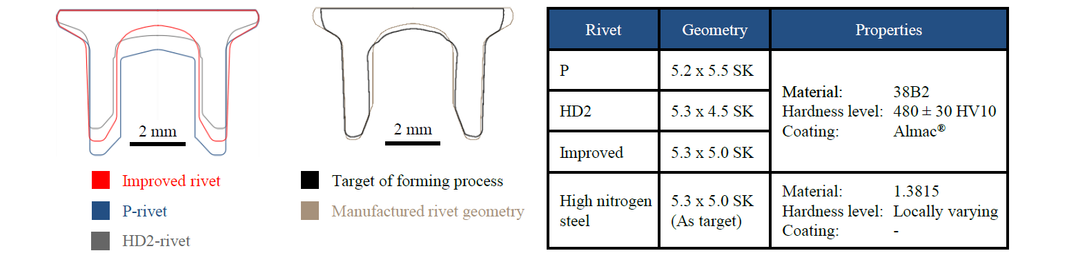
Fig. 3. Rivets under investigation and their properties according to [3]
Experimental tests are conducted to determine the strength of the riveted joints. For manufacturing the joints, a riveting tongs of type TOX TE-X 80.250.351 (TOX® PRESSOTECHNIK GmbH & Co. KG, Germany) is used. The joining velocity is 80 mm/s. As per [13], the load condition for characterising the joint strength is classified as a function of the fluctuation over time and the direction of the force. In the course of the present investigation, the joints are tested under three different load conditions. Quasistatic tests under tensile and shear load and cyclic tests under tensile load are conducted. The LWF-KS2-specimen is used to determine the joint strength. Only the LWF-KS2-concept allows the use of a single specimen geometry for all the load conditions. The quasistatic tests are carried out at room temperature with a testing velocity of 10 mm/min using the universal testing machine Zwick Z1484 (ZwickRoell GmbH & Co. KG, Germany). The test ends with the complete separation of the joined specimen. The force is measured at the traverse of the testing machine. The strain is measured by the GOM ARAMIS system (GOM GmbH, Germany). Five specimens are tested for each rivet and load combination of the material to be joined. After the tests, the measured force-strain-curves are evaluated and the failure mode is classified in accordance with the known patterns in Fig. 2. For the analysis of the fatigue strength, Wöhler curves are generated. For this, load-controlled tests with three load horizons and five repetitions each are conducted at a load ratio of R = 0.1. The loss of stiffness, which is marked by a defined frequency loss of 5 Hz or the surpassing of 2 x 10⁶ cycles, serves as a termination criterion. For the tests under cyclic load, a resonant testing machine of type RUMUL Testronic 150 kN (Russenberger Prüfmaschinen AG, Germany) is used. The machine is operated at full resonance. The test frequency results from the vibrating masses in the machine and the stiffness of the specimen and is about 40 Hz.
3 Results and Discussion
At the beginning of the investigation, experimental joining tests are carried out. The joining parameters for P-rivet, HD2-rivet and improved rivet are taken from [3]. With the high nitrogen steel rivet, the joining stroke is adjusted due to the deviation in the rivet length. The cross-sections of the joints riveted with high nitrogen steel rivets by comparison to the joining results from [3] are shown in Fig. 4. Additionally, the joining stroke and the measured joining force of the individual joints are given. All joints meet the required quality in the respect of the characteristic joint parameters.
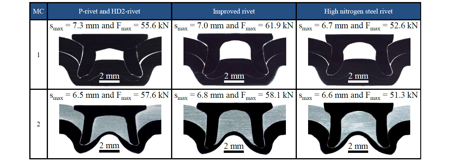
Fig. 4. Cross-sections of severed joints and joining parameters with different rivets
The joint strength is determined by experimental tests as explained above. The determined strengths of the joints under quasistatic load are shown in Fig. 5. As already mentioned in [14], it must be noted that the shear strength is higher than the tensile load in general. The dependency of the joint strength on the material strength of the parts to be joined, which is also explained in [14], is evident in the present study too. The strength of the aluminium limits the joint strength regardless of the rivet properties. However, the joint strength is significantly influenced by the selected rivet and the main differences caused by the rivets are not influenced by the load direction.
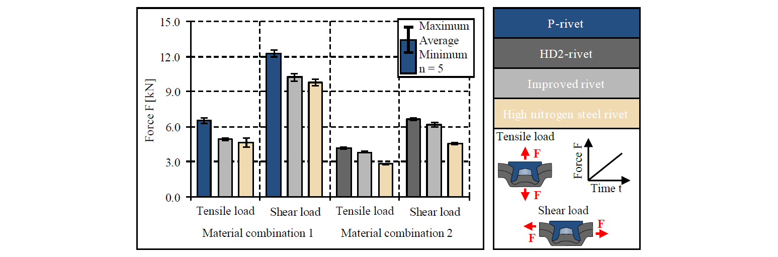
Fig. 5. Joint strength under quasistatic load with different rivets
The strength achieved with the improved rivet compared to the P-rivet is lower with material combination 1, while the difference compared with the HD2-rivet with material combination 2 is small. With material combination 1, the strength achieved by the high nitrogen steel rivet is similar to the strength achieved by the improved rivet. With material combination 2, however, the strength achieved by the high nitrogen steel rivet is even lower than that for the improved rivet. The reasons for these insights can be determined by means of an analysis of the joint failure mode (see Fig. 6). With material combination 1, the joints fail in all cases through the tearing of the rivet foot from the die-sided sheet. In this case, the amount of interlock has a big influence on the joint strength, and the lower interlocks achieved by the improved rivet and the high nitrogen steel rivet compared to the P-rivet are one of the main reasons for the lower strength. With material combination 2, the joints fail under tensile load through the tearing of the rivet head from the punch-sided sheet. Because of that, the strength achieved with the improved rivet is similar to the strength achieved by the HD2-rivet. The drop in strength that results when using the high nitrogen steel rivet is caused by the even smaller diameter of the rivet head, which is a consequence of the deviations caused by the forming process. Under shear load, the joints with HD2-rivet and improved rivet fail through the tearing of the rivet foot from the die-sided sheet. With the high nitrogen steel rivet, by contrast, the joint fails through a combination of the tearing of the rivet head from the punch-sided sheet and the tearing of the rivet foot from the die-sided sheet, which is also a consequence of the smaller rivet head diameter. The failure modes tally with the insights of [15]. With material combination 1, the determined joint strength is higher than the determined strengths with a similar material combination in [15] even for the high nitrogen steel rivet, while the joint strength with material combination 2 when using the high nitrogen steel rivet is on the same level as the results of [15].
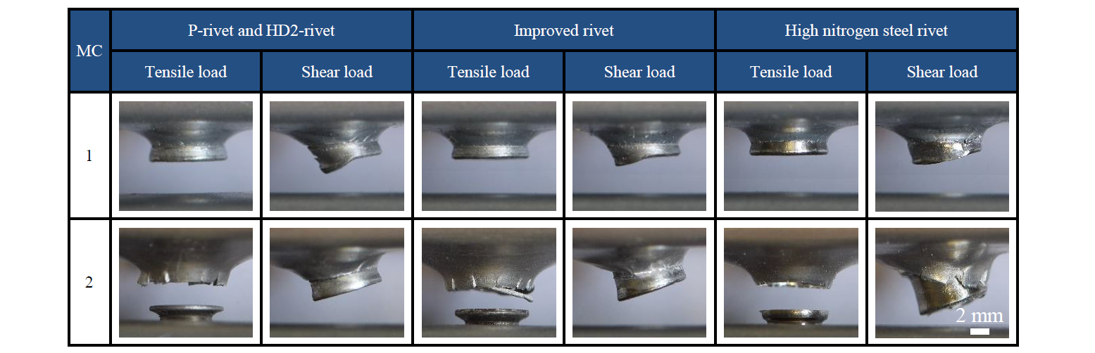
Fig. 6. Failure modes under quasistatic load with different rivets
The results of the Wöhler fatigue tests are shown in Fig. 7. With material combination 1, the fatigue strength with the improved rivet is shifted to a lower number of cycles compared to the fatigue strength with the P-rivet. The Wöhler curve with the high nitrogen steel rivet starts at the same amount of cycles as with the P-rivet, but the straight is more inclined. The joints fail, regardless of the type of rivet used, through the fracture of the rivet. With material combination 2, the results with HD2-rivet and improved rivet are very similar. With the high nitrogen steel rivet, starting at a similar number of cycles at the highest load horizon, the straight is more inclined. With material combination 2, no fracture of the rivet can be observed. In all cases, it is a fracture of the punch-sided aluminium around the rivet that occurs. Based on the findings of [16], it can be assumed that the fatigue strength under shear load is even higher than under tensile load, as is also the case with the tests under quasistatic load.
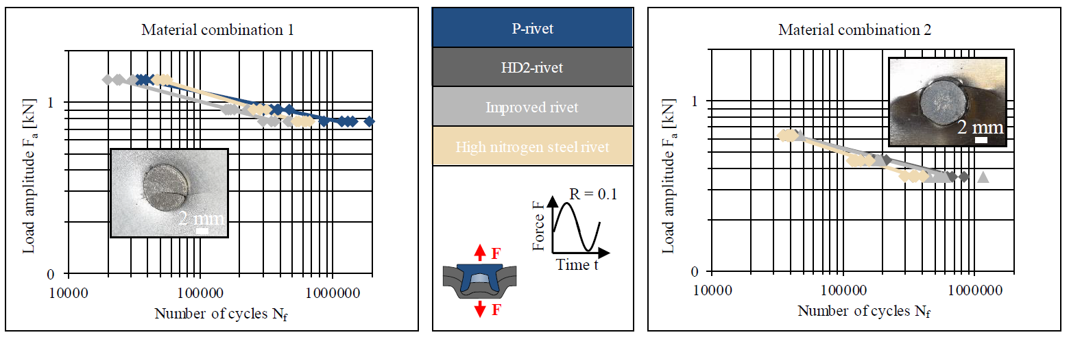
Fig. 7. Fatigue strength and failure modes of the joints with different rivets
4 Summary and Outlook
Driven by the advantages of rivets made of stainless steel, a concept for the use of high nitrogen steel as a rivet material was elaborated in previous papers. The present investigation focusses on the strength of self-piercing riveted joints with conventional rivets and rivets made of high nitrogen steel 1.3815. The joint strength for two different material combinations including the high strength steel HCT780X and the aluminium alloy EN AW-5083 is determined by experimental tests under quasistatic and cyclic load. Additionally, the joint failure mode is analysed leading to a more detailed process comprehension. For material combination 1 consisting of HCT780X on both sides, the joint strength achieved when using high nitrogen steel rivets is comparable to the results when using conventional rivets. On the contrary, for material combination 2 with punch-sided EN AW-5083 and die-sided HCT780X, the joint strength is lower compared to joints with conventional rivets. The main failure mode with high nitrogen steel rivets for material combination 1 is the tearing of the rivet foot from the die sided sheet. In this case, the lower strength of the joints with high nitrogen steel rivets can be attributed to the smaller interlock formation compared to P-rivets. As concerns the failure behaviour for joints of material combination 2, the failure mode differs depending on the load. Under tensile load the tearing of the rivet head from the punch-sided sheet is the reason for failure, while under shear load an additional tearing of the rivet foot from the die-sided sheet occurs. The observed results can be correlated with deviations between the target geometry and the actually achieved geometry of the manufactured rivets, which are a consequence of the reduced forming stroke. Thus, the lower joint strength results from the smaller head diameter of the high nitrogen steel rivets. Nevertheless, a competitive joint strength is achieved using the new rivets. Overall, based on the results of the present investigation, it can be stated that joints with an adequate strength can be realised with rivets made of high nitrogen steel. Thus, the high potential offered by high nitrogen steel as rivet material is confirmed. Future studies will involve correcting the deviations due to the forming process and improving the joint strength through the local adjustment of the material strength within the rivet. In addition, the corrosion resistance of the rivets and riveted joint will be examined.
Acknowledgements
The authors would like to thank the German Research Foundation (DFG) for their support of the research project “Forming and joining of semi-tubular self-piercing rivets made of high-strength steel with adapted mechanical properties and numerical analysis of the process chain” (ME 1840/8-1, Project-ID: 328853593), on which this paper is based.
