1 Introduction
Owing to the lightweight construction of car bodies, increased usage of lightweight materials, e.g., aluminium and magnesium, have been using in car body construction in addition to the classic steel materials. In car body assemblies, different components made of varying materials should be joined together. As a fixing method for hybrid joining with structural adhesive, mechanical joinings have the advantage of being able to fasten the joining partners of different materials without thermal introduction. In addition to the qualification of the joining process and the joint load-bearing capacity, the focus of the implementation of a novel joining process is on the characterisation of the dimensional stability. Hahn et al. [1], Neugebauer et al. [2] showed an out-of-plane bending of die-sided sheet in solid punch riveting due to the lack of the tool support. The bending effect is accumulated in the case of multiple joining, which leads to a gap formation. Similar distortion, although in the punch-sided joining partner, can be seen in the self-piercing riveting as well [3, 4]. In clinching, a strong in- and out-of-plane material flow occurs during plastic deformation, which causes an internal tensile stress in the sheet. If the fixing effect between the blank holder and the die cannot compensate for the tensile stress, the sheets joined bend up [5].
With regard to the shear-clinching (Fig. 1) [6] besides the penetration of the material in the out-of-plane direction, the material flows radially outwards during the joining process due to the hemispherical outer punch [7], so that a strong bending of the ductile joining partner on the punch side occurs [8]. Han et al. [9] indicated the modification of inner punch and blank holder is efficient in shear-clinching to decrease the out-of-plane bending further on the gap between the sheets and the global distortion. In addition, Hörhold [10] showed numerically that the outer punch radius and the friction conditions between the joining partners are decisive for the distortion as well. In general, these distortions can be determined experimentally using various optical measuring methods [9]. Numerically, the dimensional changing of joint partners in case of axial-symmetric joining can be estimated by means of two-dimensional modelling. However, in case of an asymmetrical scenario, a three-dimensional model is required.
To date, there are many approaches to the setting up of a three-dimensional model. Masendorf et al. [11] created a three-dimensional half-model by rotating the two-dimensional surface. Afterwards, the half-model is assembled with a single overlapped joint, so that the asymmetrical load simulation can be realised under three-dimensional condition. Dean et al. proposed in [12] a method for building up a three-dimensional clinching framework. It enables, by using of a user-defined anisotropic plasticity model, to evaluate the influence of anisotropic material behaviours on joint characteristics. Since the three-dimensional adaptive remeshing works in case of extreme deformation and subsequent material failure unstably in current commercial solvers, a full or partial three-dimensional model of a joining process, taking into consideration the fact that the material damage is still a challenge [13]. To overcome this difficulty in the simulation, some meshless approximations based on bond-based failure are common. Huang et al. [14] indicated a full three-dimensional SPR insertion modelling using Smoothed Particle Galerkin (SPG) method. Owing to the adaptive Lagrangian kernel in SPG, the large deformation during insertion can be defeated. By means of a defined bond failure criterion, the study shows a good agreement of joint properties between the simulation and the experiment. Similarly to this idea, the substitute modelling of shear-clinching with a material separation criterion, which is based on a defined separation stress of segments, is presented in this study.
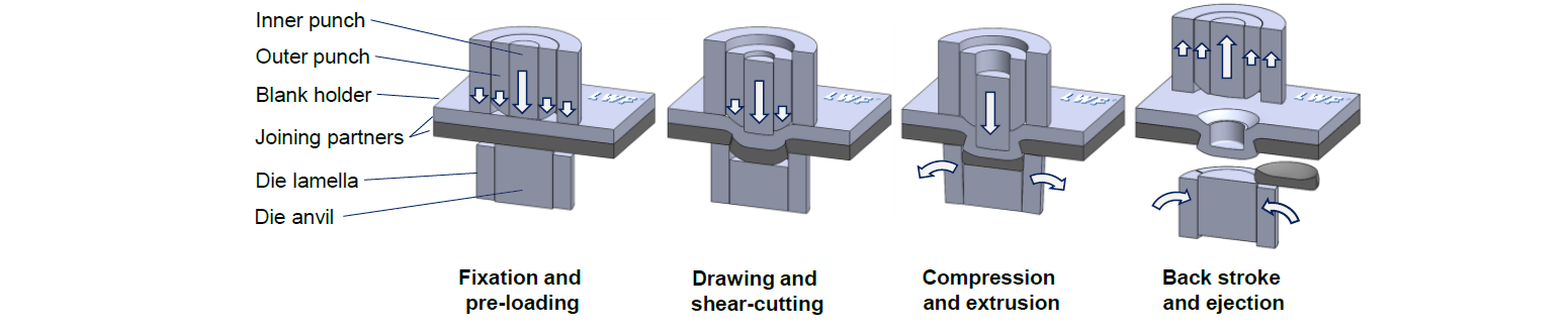
Fig. 1. Setup and principle of shear-clinching
2 Experimental procedures
The shear-clinching in this study employs a mixed combination of EN AW-6016 T4 and 22MnB5. The EN AW-6016 T4 assigned on the punch side has a sheet thickness of 2.0 mm. The 22MnB5 on the die side with a sheet thickness of 1.5 mm is press-hardened with an AlSi-coating. The detailed description of material properties is shown in Table. 1. A servo motor-driven clinching system ECKOLD DFG 500/150E with a feed speed of 40 mm/s was applied for joining. With regard to the shear-clinching system following [15], the punch-side tool set has an inner diameter di = 5.6 mm, the outer punch radius r = 6.0 mm. An opening die was positioned on the die side. The anvil has a maximum countersink mT = 2.1 mm. A 30 mm x 30 mm specimen for the single joining was used. The characteristics (Fig. 2) of joints were determined in microsections.

Fig. 2. Characteristics of a shear-clinched joint
Table 1. Mechanical properties of materials used

3 FE Modelling
Numerical simulations were performed using Simufact Forming 16.0, which enables a user-friendly modelling of mechanical joining processes, both two-dimensional and three-dimensional. To describe the plastic deformation of the joining partner, the flow curves of the materials described in Table 1 according to [16] were used. A Coulomb friction μ = 0.25 was defined according to [16] in the simulation.
A validated two-dimensional model for the shear-clinching has already been presented in [10]. The focus of this study is on the development of a three-dimensional model, which can be used for estimating the component distortion in asymmetrical situations numerically. In current Simufact Forming solvers, the forming process in the punch-sided sheet can be set up without damage criteria. Three-dimensional implementation of the separating process in the die-sided sheet remains a major challenge. The basic idea behind the design of a shear-clinching substitute model is creating an artificial separating plane in the die-sided joining partner during pre-processing. The separation process is defined by a segment-to-segment contact behaviour. In fact, a two-part die-sided sheet was constructed to implement the artificial separation plane. That means a pre-punched sheet and a slug. It is designed such that at the beginning of the joining process the two components remain bonded. During the joining process, they separate according to the stress, so that the shear-clinching separation process is carried out. Therefore, the focus is on the definition of the separation stress and the design of the separation plane.
In Simufact Forming, the contact settings of individual contact pairs is specified in the ‘Contact table’. Under the function ‘Mechanical properties’, it is possible to configure that the surface contact will be released when the normal stress of a node/ segment is higher than the defined separation stress. To stabilise the separation process, the contact tolerance and the contact bias factor can be applied.
To obtain a basic understanding of the separation process using separation stress, a two-dimensional punching simulation was applied. As shown in Fig.3, a non-linear separation line was designed in the 22MnB5. The small section with a height in z-direction of 0.23 mm corresponds to the edge feed and smooth cut area. The rest of the line clones the fracture surface. All of the values are taken from the experiment results in [10]. The difference in diameter of 0.02 mm in the small section is due to the setting of a delay in the cutting process. The reason for this is that the smooth cut area is mainly formed under shear stress, which cannot be defined using the separation stress. In addition, the meshing of the slug and the pre-punched 22MnB5 are shown in Fig. 4.

Fig. 3. Setup of a 2D-punching simulation with pre-punched sheet and artificial slug
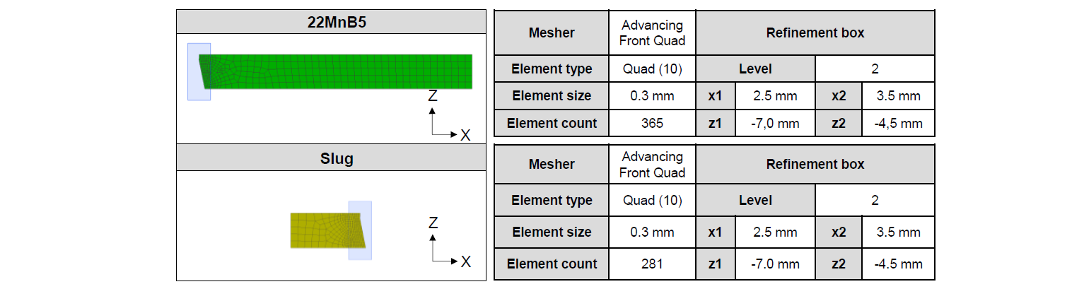
Fig. 4. Details of meshing in the punching simulation
After determining the separation stress for the shear-clinching is the separation plane on it. A theoretical separation line can be determined using the post-particles. In fact, ten post-particles were added along the fracture surface at 100%-forming in two-dimensional shear-clinching simulation. Afterwards, the original positions of the particles can be backtracked at 0%-forming. As Hörhold has already clarified the accurate description of the two-dimensional shear-clinching simulation in [10], it will not be repeated in this study. However, the backtracked line does not look like a regular line. Furthermore, it is difficult to clone the line exactly in a three-dimensional simulation. Therefore, a smooth line (Fig. 5) was used.
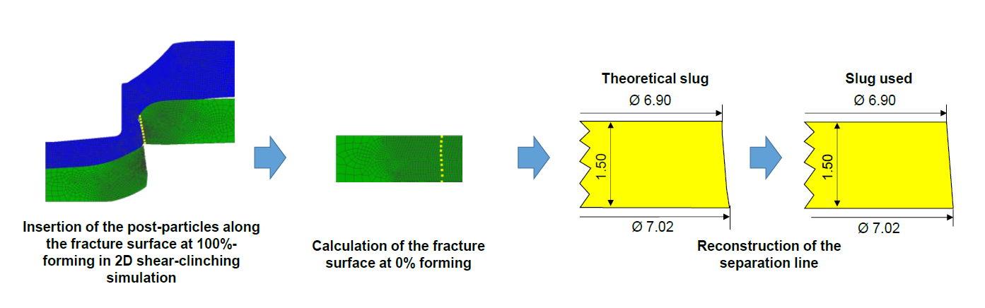
Fig. 5. Determination of the separation line in a shear-clinching simulation
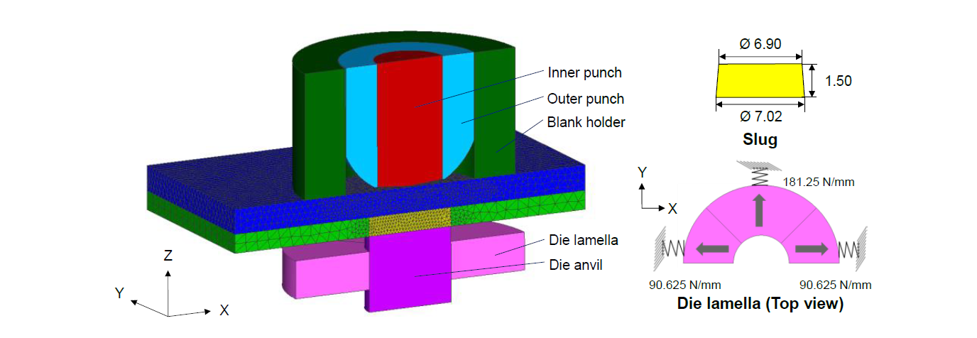
Fig. 6. Setup of a 3D-shear-clinching substitute modelling

Fig. 7. Details of meshing in the 3D-shear-clinching substitute modelling
Based on the two-dimensional shear-clinching framework, the setup of the three-dimensional substitute modelling is shown in Fig. 6. A half-model was used in order to reduce the computing time. The die lamella were built up as in real world, which allows a radial expansion. The lamella yielding in –x-direction is set as in [6]. In addition, the meshing of the components are shown in Fig. 7. In this study, a two-dimensional axially symmetrical substitute modelling was used as well, in which the die lamellae are designed in the form of an elastic hollow cylinder. Otherwise, the tool geometries and tool kinematics remain identical.
4 Findings and Discussion
For each cutting gap configuration, the punching simulation was carried out with different separation stresses. If the separation stress is too low, the punching is completed with a small maximum punch force. If the separation stress is too high, the artificial slug sticks longer to the pre-punched sheet, so that the sheet is strongly plastically deformed by the feed of the punch. As a result, the pre-defined separation line loses its dimensional accuracy. In order to determine the appropriate separation stress σ, the hole geometry after punching was considered in addition to the comparison of the maximum punch force Fp. It has been found that, taking this criterion into account, a few separation stresses can be specified for each cutting gab configuration. In this study, three separation stresses of each variant were recorded. The findings demonstrated in Fig. 8 show a good agreement between the simulation and experiment in case of the break angle β’. However, the maximum experimental punch force is slightly higher than simulated. The difference is due to the fact that during the punching the slug is cut under superimposed shear and normal stresses. In fact, the lack of limitations of a separation using separation stress findings in a smaller maximum punch force. Furthermore, by positioning the simulation findings with respect to the break angle β’ after punching and the separation stress σ (Fig. 9), a polynomial correlation (1) is determined. The separation stress σ tends to increase as the break angle β’ rises, thus defining a separation criterion for the shear-clinching simulation.

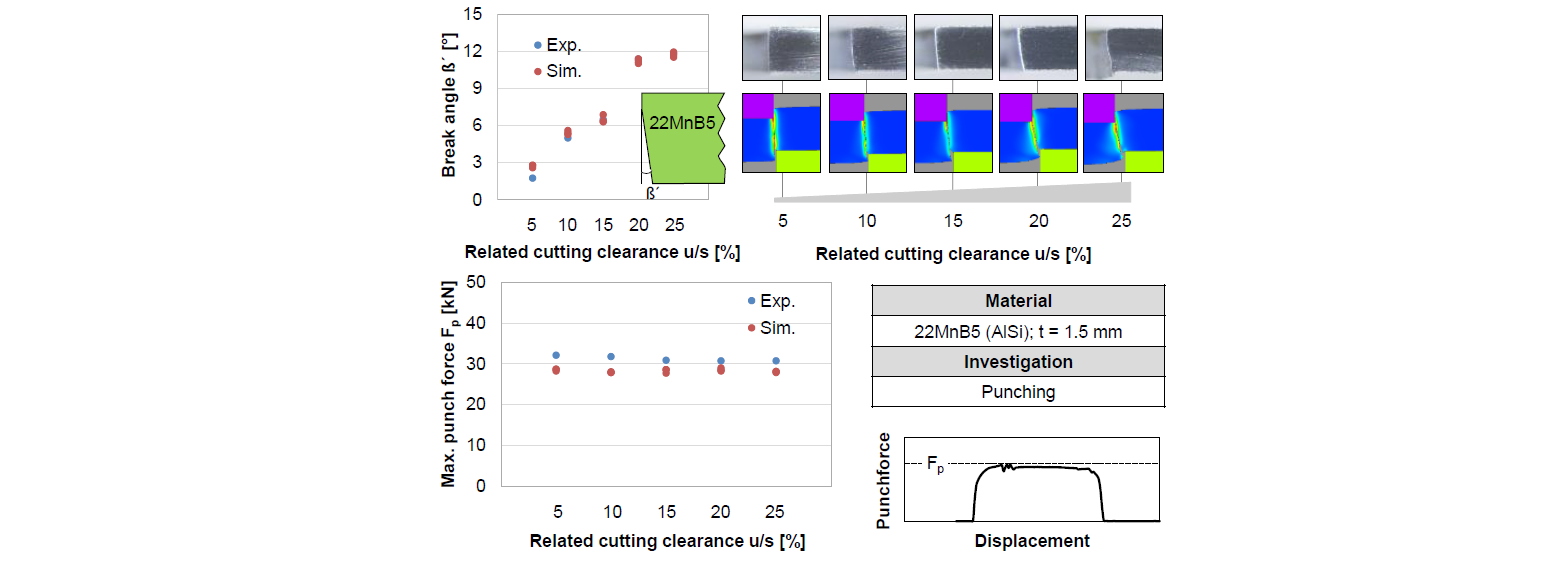
Fig. 8. Findings of the shear-cutting simulation using two-dimensional substitute modelling

Fig. 9. Derivation of the correlation between the break angle and the separation stress
The shear-clinching substitute model was tested initially for axial symmetric condition. Regarding the experimental investigation, the average break angle β in the steel portion after joining is 11°. This allows the separation stress σ to be set at 1450 MPa. In fact, a separation stress σ of 1570 MPa, with in the scattering range, was combined with contact tolerance and bias factor defined to ensure a stable process as well as good agreement between experiment and simulation. As demonstrated by the findings provided in Fig. 10, the shear-clinching substitute model built offers a good potential to represent the shear-clinching process qualitatively.
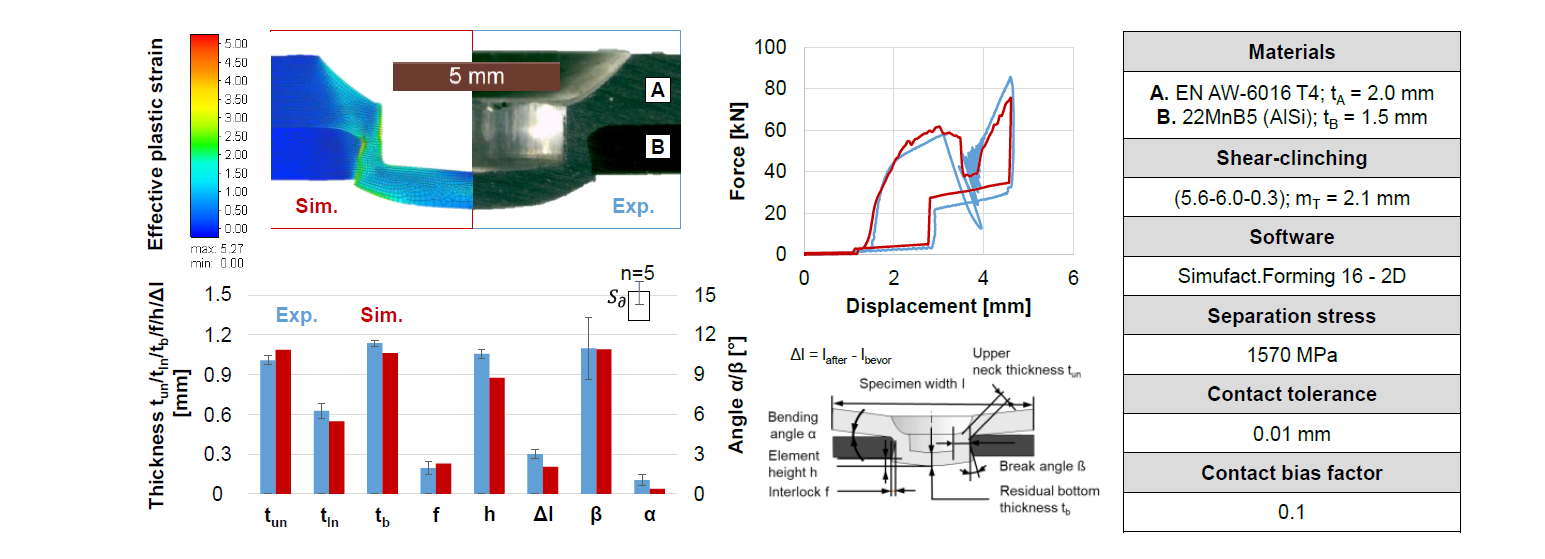
Fig. 10. Comparison of experimental findings and shear-clinching simulation using two-dimensional substitute modelling
In a three-dimensional simulation, the major challenge is to determine a compromise between the computational effort and the model accuracy. In order to reduce the computing time, a bigger element length was generally chosen. In addition, it was found that an automatic contact behaviour can significantly speed up the simulative process. However, in case of automatic contact, equilibrium of the entire system is required at the beginning of the simulation. In shear-clinching, the sheets are fixed between the blank holder and the anvil. Instead of a blank holder spring preload of 2.8 kN in two-dimensional simulation, a spring preload of 1.4 kN was defined in three-dimensional simulation in both the blank holder and the anvil. In terms of meshing, the tetrahedral elements are calculated much faster than hexahedra. Furthermore, it was determined that the tetrahedron is better suited for the description of plastic deformation. Fig. 11 shows a good agreement between the experiment and the three-dimensional simulation with regard to the force-displacement curve and the distortion. The separation stress verified in Fig. 10 works at this point as well. Using eight cores, it takes about two hours to calculate the joining process. Due to the rough meshing, the geometric accuracy in the simulation cannot be properly guaranteed. The significant deviations can be seen both in the joint characteristics and in the joint distortion. Other imperfections are due to the back stroke in the simulation since the contact tolerance was exceeded. In general, it can be said that the three-dimensional model built can offer a qualitative evaluation of the joint part distortion.
A great benefit of the 3D substitute model built is that the component distortion can be estimated in a non-axially symmetrical situation. As Fig. 12 shows, the joint is positioned asymmetrically in the sheet plane. Due to the different flow resistance in the aluminium part around the joint, more material was displaced to the side with small edge distance. This has resulted in a bulge at the edge. On the other side, which has a large edge distance, the sample edge remains unbent. Thanks to the built-up substitute model, not only the geometric changes but also the critic stress-strain states in the joining partner and especially on the narrow flange can be clearly determined.

Fig. 11. Findings of the shear-clinching simulation using three-dimensional substitute modelling
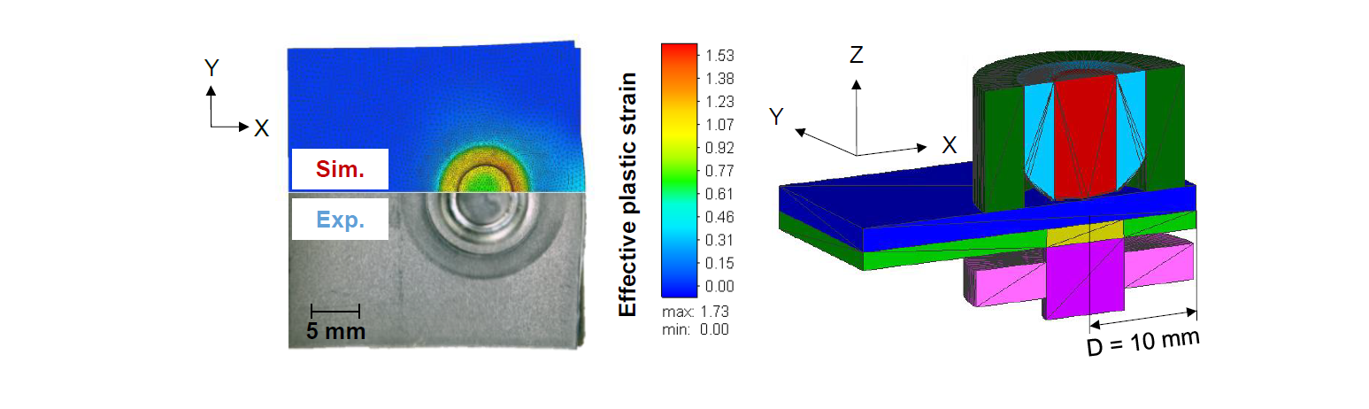
Fig. 12. Findings of shear-clinching asymmetrically
5 Summary
A three-dimensional shear-clinching substitute framework is shown in this study, in which the axially symmetrical and asymmetrical distortions can be estimated with low computational effort. In order to enable a fast and stable joining simulation, a defined separation plane in combination with a separation stress replaced the common macro mechanical fracture criteria in the die-sided sheet. The separation line was determined using post-particles in a validated two-dimensional shear-clinching simulation. The separation stress σ correlates with the break angle β’ in the die-sided sheet, which was defined by a punching simulation. Therefore, a three-dimensional substitute model was built. The functionality of the substitute modelling was tested initially axially symmetrical and then investigated with a quadratic half-model. In addition to the expansion of the punch-sided sheet, the bending-up effect was visible in the simulation. During the comparing experiment and simulation, the built three-dimensional shear-clinching substitute model was validated. Furthermore, the distortion by an asymmetrical joint was simulated using the substitute model built. This offers the possibility to numerically evaluate the influence of a local modification of the tool on the asymmetrical component distortion.
This study showed a three-dimensional modelling possibility for the mechanical joining processes containing a material separation. By eliminating the damage criteria, the simulation can be stabilised. Thus, a three-dimensional joining process can be realised within an acceptable calculation time with potential good dimensional accuracy. However, the material-specific separation criterion determined is only suitable for the 22MnB5. It should be noted that, the three-dimensional substitute model works if the slug separation is symmetrical. Future work will determine experimentally to what extent the slug remains symmetrical, so that the application limit of the model can be defined exactly. In addition, the influence of friction on the joint distortion will be investigated.
Acknowledgements
The authors gratefully thank the German Research Foundation for funding the used tools and equipment within the research project “Mechanical joining of dissimilar materials by shear clinching processes without pre-punching”.
