1 Introduction
To satisfy the increasing demand, aircraft manufacturers are looking for new materials and techniques to increase the capacity and the production rate of aircrafts i.e. continuous fibres composite materials. Among others, carbon fibres composite materials are characterized by high specific properties, compared to aluminium alloys, allowing mass reduction of aircrafts. Classically, high performance aeronautic composite parts are manufactured using prepreg plies, draped and cured by autoclave. This technology is considered as the reference in term of quality and mechanical properties. However, the prepreg manufacturing technique is quite long and expensive (storage, tooling, etc…). To overcome these limitations, aircraft manufacturers are investigating other manufacturing processes such as Liquid Composite Moulding (LCM). LCM consists in forming dry stacks of plies and adding a liquid resin afterwards to obtain the final part. No autoclave curing is needed, allowing production rate increase. At the same time, dry plies don’t need any specific storage facilities, helping to reduce storage costs. The HiTape® reinforcement, developed by Hexcel Reinforcements, is a newgeneration reinforcement dedicated to LCM. Composed of UD carbon fibres, maintained together by a low-density thermoplastic veil on both sides of the reinforcement, HiTape® is adapted to automated laying to obtain flat stacks that can be used for LCM.
The forming stage of these flat stacks strongly defines the final mechanical properties of the part and determines the possible defects such as wrinkling or peeling. Understanding and modelling HiTape® plies forming is then important to predict and increase the final part quality. The forming process considered in this work is called double-diaphragms moulding (Fig. 1). It consists in compacting a stack of HiTape® plies between two flexible membranes using vacuum to reach the 60% volume-fibre ratio (VFR) requirement imposed by aircraft manufacturers. Then, the stack is heated up to the melting temperature of the veil, allowing mobility between plies, facilitating forming and reducing defects generation. Finally, plies are deformed on a mould to obtain a three-dimensional dry preform, after cooling, ready for infusion/injection (Fig. 2).
The study developed in this paper aims to model the forming of a HiTape® stack using double-diaphragms process. Firstly, plies are studied individually. Afterwards, the stack is considered and a particular attention is paid to inter-ply areas.
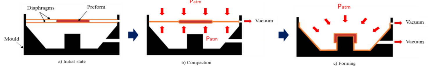 Fig 1. Double-diaphragms forming process.
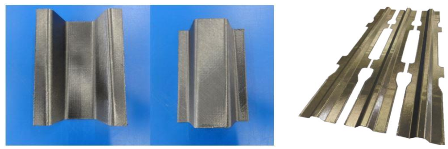 Fig 2. Examples of three-dimensional HiTape® preforms (after forming) [1] [2].
2 Description of the behaviour of a preform
2.1 Observation scales
We can consider three different scales to study composite materials (Fig. 3). The macroscopic approach describes the stack as only one continuous homogenous body. This approach offers low computation time but can introduce significant errors by neglecting inter-ply interactions. Using the microscopic scale, every single fibre of the reinforcement, as well as the intra-ply and inter-ply interactions, are modelled. This approach offers more precision but is also the most expensive one in term of computation time. Finally, the mesoscopic approach consists in modelling every ply of the stack as a continuous medium. Therefore, interactions between plies are considered but deformations are homogenised over the ply. This approach is a good compromise between computation time and accuracy. Moreover, characterization of plies and inter-plies behaviours for HiTape® stacks have be conducted in previous works by Bouquerel [5] [6].
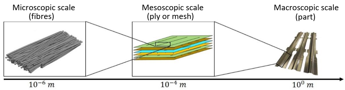 Fig 3. The different observation scales available for fibrous reinforcement stacks [1] [3].
2.2 Description of a ply and modelling
The HiTape® reinforcement is composed of long carbon fibres placed side by side to obtain UD tapes about 0.2 mm thick and 6.35 mm to 500 mm wide. On each side, a very lightweight and thin thermoplastic veil is placed to maintain the fibres in position and to facilitate handling and stacking of plies (Fig.4). Carbon fibres are well known for their quasi-inextensibility and their low bending stiffness due to their slenderness. Moreover, the low mechanical properties and density of the veil can’t provide any significant strength to the ply in any direction. Therefore, the UD fibre placement leads to transversely isotropic behaviour of the HiTape® ply whose plane of isotropy is normal to the fibre direction. This behaviour is characterized by quasi-inextensibility in the fibre direction and rigidities several decades lower in compression and following the others directions.
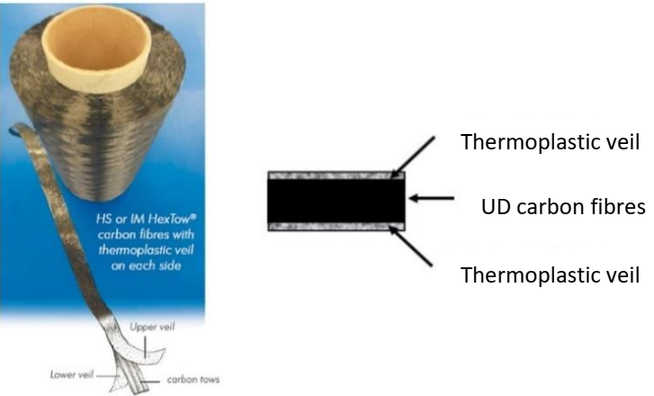 Fig 4. Presentation of the HiTape® reinforcement [1].
In this study, we consider a mesoscopic approach, modelling each ply of the stack as a transversely isotropic continuous medium. Regarding this hypothesis, the main deformation modes of a ply (Fig. 5) are those defined by the continuum mechanics (CM) for a fibrous medium: traction, compaction and shearing. However, these only modes are not enough to fully describe the complex behaviour of a HiTape® stack. Other deformation modes specific to structured reinforcements must be considered: out-ofplane bending, inter-ply sliding (friction) and opening.
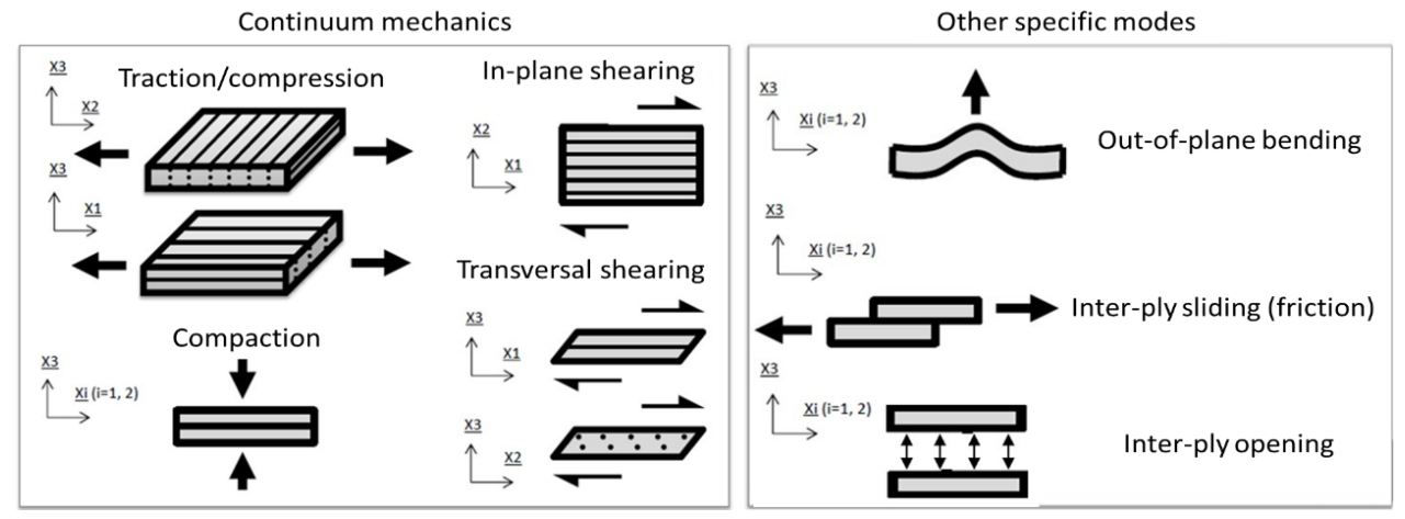
Fig 5. Deformation modes defined for structured composite reinforcements [4].
The out-of-plane bending behaviour of a fibrous ply strongly differs from the one defined for a continuum medium. Internal movements of fibres can occur during deformation, leading to a bending stiffness several times lower than the one defined for a continuous medium having the same membrane stiffness. In her work, L. Bouquerel [5] [6] characterizes the bending behaviour of HiTape® plies and highlights the non-linearity of the bending moment/curvature relationship (Fig. 6).
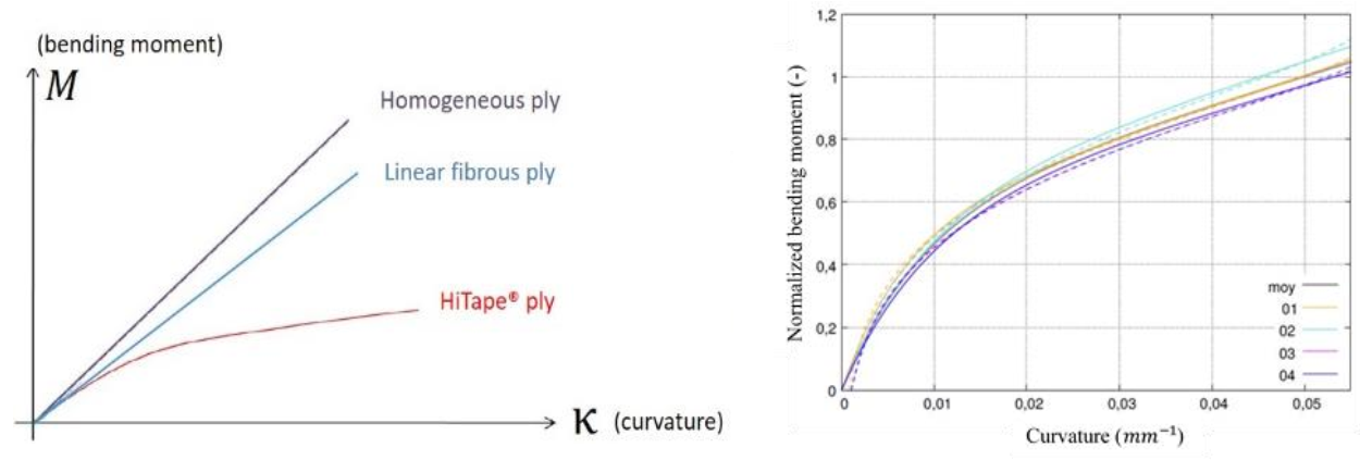
Fig 6. Description of the bending moment/curvature relation for different materials and experimental results obtained for one ply of HiTape® reinforcement [5]
2.3 Inter-ply behaviour
The bending moment/curvature relationship investigated by Bouquerel [5] [6] highlights that the HiTape® stack bending stiffness cannot be directly related to the bending stiffness of a single ply (Fig. 7). Inter-plies introduce a softening of the bending behaviour of stacks. This can be associated to a concentration of deformation along the inter-plies. Thereby, inter-plies modelling is mandatory to obtain reliable results.
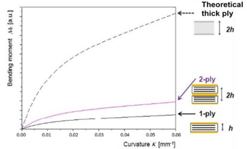 Fig 7. Impact of the inter-ply on the bending behavior of a HiTape® stack [4].
Characterization of the tangential behaviour of the interface between two HiTape® plies was conducted by Bouquerel [5][6] using a brand-new pull-through friction bench. The obtained tangential force/displacement relationship shows an increasing tangential force followed by a progressive damaging of the interface and tends toward a pure frictional state (Fig. 8.(a)). Dependency of the tangential behaviour to the pressure and sliding speed is also emphasized by this study (Fig. 8.(b)). Orientation of plies can influence the inter-ply tangential behaviour too [7] but still have to be characterized for HiTape® reinforcements.
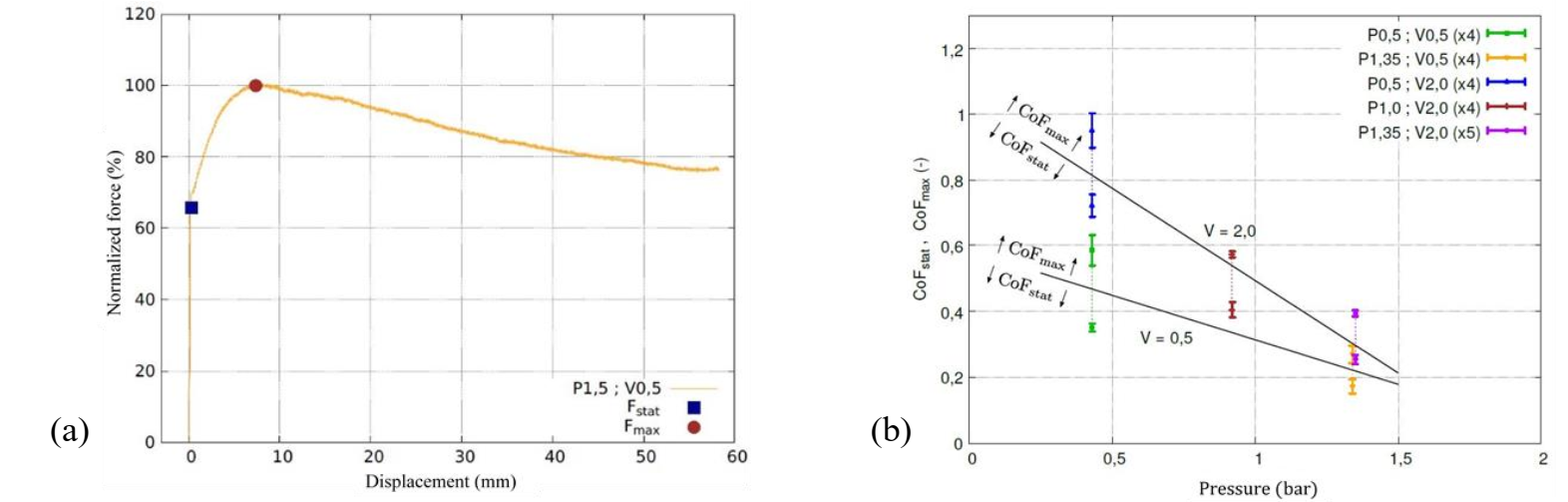
Fig 8. Tangential force/displacement relation of the interface between two HiTape® plies oriented along the same direction (a) and influence of pressure and sliding speed on friction coefficient (b) [5].
3 Numerical strategy
3.1 Element definition
One of the first problems to be solved when considering modelling the forming of HiTape® stacks using FE methods is the ply slenderness. Classically used linear or quadratic brick elements (respectively C3D8 and C3D20 in Abaqus) present strong locking phenomena for bending dominated applications at high aspect ratio. So, they cannot be considered for this application. Shell elements are sometimes used to model composite plies. However, shell elements have both displacement and rotational degrees of freedom (DoFs). Thereby, associating shell elements with others elements with only displacement DoFs is difficult. Moreover, the virtually zero-thickness of classic shell elements doesn’t allow for a straight representation of 3D stacks of plies.
In order to overcome these difficulties, specific solid-shell elements are considered. These elements combine displacement DoFs only and the 8-nodes 3D definition of brick elements, with the proper bending behaviour of shell elements, even for high aspect ratios. The chosen element was developed by Vu-Quoc et al. [8] and is implemented in Abaqus (CSS8 element). Based on the hexahedral element theory, the CSS8 element formulation is improved using Enhanced Assumed Strain (EAS) and Assumed Natural Strain (ANS) methods to pass both the membrane and the out-of-plane bending patch tests, even at high aspect ratios (several hundreds) [8]. These two methods consist in adapting the deformation field of the element by modifying or adding a term to some selected components of the Green-Lagrange strain tensor. Thereby, thanks to intelligent EAS and ANS modifications, most of the locking phenomena can be overcome (membrane, shear, Poisson-thickness and curvature-thickness). Considering the intraply shear locking [9] [10], no problems have been raised yet.
3.2 Constitutive law of a ply
The constitutive law defines a relationship between stresses and strains. Previously, we introduced the deformation modes that have to be modelled regarding a HiTape® ply. Only intra-ply deformation modes are considered here. Inter-ply phenomena will be considered afterwards (paragraph 3.3).
First, we consider an elastic non-linear behaviour for HiTape® plies. During forming, plies will undergo large deformations. Two principal approaches are used to model the behaviour of such an elastic fibrous material under large deformations: hypoelastic and hyperelastic models. Hypoelastic constitutive models link stresses and strains rates. They are generally used for material presenting small anisotropy. Moreover, the definition of an objective stress-rate tensor raises many difficulties.
Hyperelastic models (chosen in this work) are special cases of the hypoelastic theory supposing a non-dependency on time of the material behaviour. The hyperelastic theory is based on a simplified version of the Clausius-Duhem inequality, supposing no heat transfer and no dissipation because of the truly elastic behaviour that we are looking for. This results in a relation between the second Piola-Kirchhoff stress tensor S̿ , the Green-Lagrange strain tensor E̿ (or the right Cauchy-Green deformation tensor C̿) and a hyperelastic potential 𝑊(C̿) (equation (1)) [5] [11] [12].

This potential defines the material behaviour and many formulations can be found in the literature. In this work, a physical invariant-based formulation is chosen which consists in defining one physical invariant, as a function of the classical invariants of C̿, to describe each deformation mode of the material. According to the decomposition principle [8], 𝑊(C̿) is written as a sum of functions describing one specific deformation mode [5] [12] [13]. The hyperelastic potential formulation developed by Bouquerel [5], using four main deformation modes (elongation, isochoric compaction, lateral compaction and shearing), is chosen (Eq. (2)).

3.3 Bending/membrane response modelling
The hyperelastic potential introduced in equation (2) doesn’t take into account the out-of-plane bending deformation mode. We described, in paragraph 2.1, the special non-linear bending behaviour of a HiTape® ply that differs from the CM. An alternative approach is proposed which consists in decoupling traction and bending behaviours by modelling each of them independently thanks to different elements. The first element is only supporting the membrane behaviour of the ply without influencing the bending behaviour. A M3D4 membrane element is then used for its capacity to only model in-plane phenomena. Considering the bending behaviour, the previously introduced CSS8 element is chosen for its good capability in modelling bending dominated situations.
Then, elements are assembled using the embedded element technique (Fig. 10) [14] [15] [16] to provide a structural element supporting both decoupled behaviours. This method consists in defining the DoFs of one “embedded” element thanks to the DoFs of a second “host” element. In this work, the host element is the CSS8 while the embedded one is the M3D4. To avoid any influence on the bending behaviour of the ply, the membrane element must be located on its neutral surface (Fig. 9). Consequently, the previously introduced constitutive law must be wisely split between these two elements: the membrane elements supporting the elongation deformation mode while the solid-shell elements support the other 3D deformation modes.
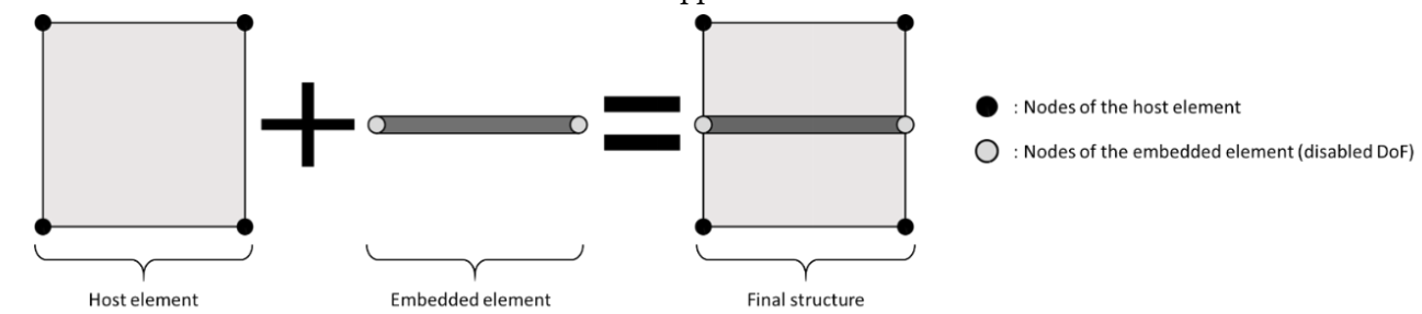 Fig 9. Embedded element principle.
3.4 Cohesive elements for inter-ply modelling
Modelling the interfacial area located between plies of a stack, under large deformations, is a real challenge. These zero-thickness areas are concentrating most of the through the thickness deformation. Characterization of the HiTape® inter-ply specific behaviour was carried out by Bouquerel [5] [6], using a pull-through friction testing bench. This specific behaviour was described in paragraph 2.3.
Many approaches can be find in the literature to described the behaviour of inter-plies inside a stack of reinforcements [17] [18] [5] [22]. Considering HiTape® stacks, the inter-ply thickness can be considered as equal to the thermoplastic veil thickness and, therefore, is negligible. Moreover, important sliding between two neighbouring plies is observed during forming. Consequently, techniques based on mesh reduction or kinematic enrichment can’t provide any sufficiently precise solution. Another approach consists in using contact algorithms. However, they are not developed to describe such a rich behaviour with cohesion, damaging and friction. Moreover, they are often accompanied by long computation times due to the numerous contact areas and are very dependent on the mesh.
Therefore, to model inter-plies in a HiTape stack, cohesive elements has been chosen. Linear cohesive elements can be described as 8-nodes zero thickness elements which behaviour is described by a traction-separation law. The literature introduces many cohesive element formulations. From the very first model only accounting for normal opening [19] to normal-tangent coupled models introducing friction [20] [21]. In order to describe the cohesive interaction as well as the friction between two HiTape® plies, a PPR cohesive zone model is chosen [22]. The behaviour of the interface is described thanks to a thermodynamically validated cohesive potential Ψ (equation (3)). First derivatives of Ψ, with respect to the normal opening ∆𝑛 and the tangential sliding ∆𝑡, correspond to the normal cohesive stress 𝑇𝑛 and the tangential cohesive stress 𝑇𝑡 respectively (equation (4))
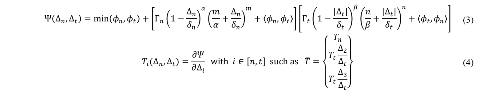
The other parameters introduced in equation (3) are fracture energies 𝜙𝑡 and 𝜙𝑛, final opening widths 𝛿𝑛 and 𝛿𝑡 and damaging shape parameters 𝛼 and 𝛽, associated to normal and tangential interactions respectively. Finally, some constant parameters associated with the normal (Г𝑛, 𝑚) and tangential (Г𝑡, 𝑛) openings are present. Graphs of the separation-traction law regarding to normal and tangential interactions are given in Fig. 10.
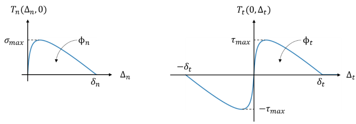 Fig 10. Stress/displacement graphs for normal and tangential interactions using PPR cohesive model.
The cohesive potential introduced by equation (3) doesn’t describe the frictional behaviour observed through experiments. In order to represent friction phenomena, when a negative normal stress (compaction) is applied to the interface, an additional term 𝑇𝑓 is added to the tangential traction 𝑇𝑡 (equation (5)). This one is calculated using a Coulomb’s friction law, where 𝜇 is the friction coefficient. To control the progressive apparition of friction, a damage-type parameter 𝜅(∆𝑡) is introduced [20].

An appropriate set of parameters for the cohesive model was determined using the results of Bouquerel’s characterization obtained with a pull-through bench. The cohesive-friction stress/displacement graph given in Fig. 11, shows the inter-ply constitutive law determined for a selected couple of pressure/sliding speed. This law is the one used for the numerical simulations introduced in paragraph 4. Dependencies on pressure and sliding speed are not considered here and will be studied later.
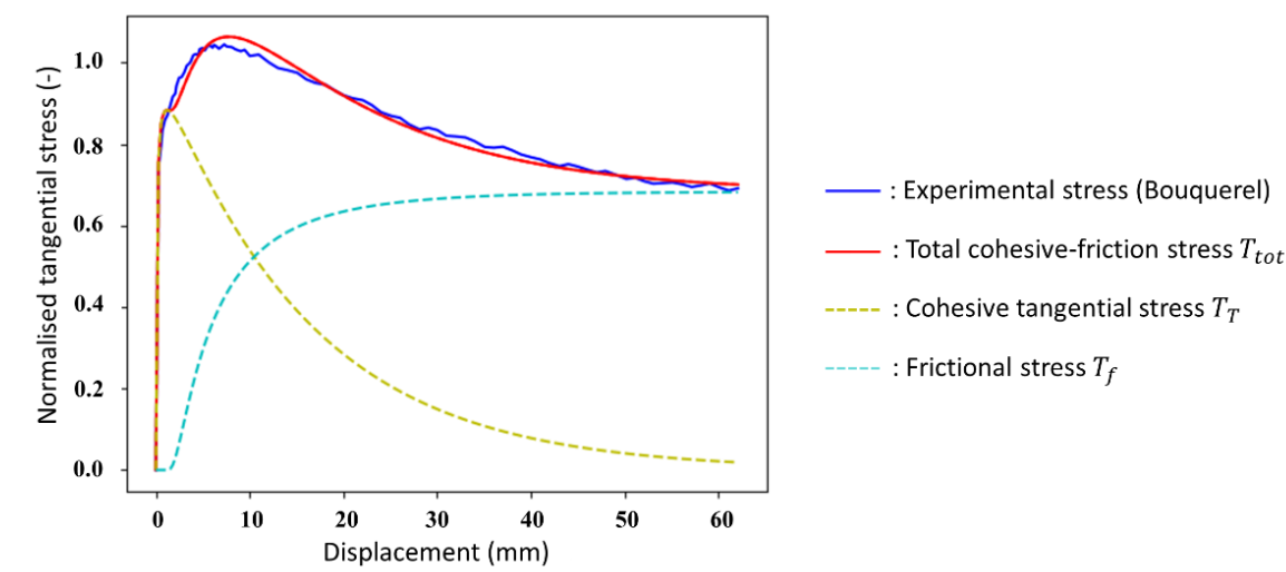 Fig11. Tangential stress as a function if displacement.
4 Results and perspectives
For validation purpose, both membrane and solid-shell element behaviours are described using isotropic elastic constitutive laws. Traction stiffness associated to solid-shell and membrane elements are determined according to Bouquerel’s experimental data [5] [6] to fit with bending and traction stiffness of a HiTape® ply.
The capability of the embedded element method to model the decoupling of traction/bending behaviours inside a ply has to be assessed. To do that, beam models, under small deformations, subjected to tensile and cantilever bending, have been studied. Deflection results obtained using embedded structures (M3D4 associated to CSS8) and only CSS8 elements are compared to the theory and confirms the capability of the embedded elements method to model one HiTape® ply.
However, our objective is to model HiTape® stacks. When stacks are considered, membrane embedded elements are no more located on the neutral surface of the structure. Consequently, membrane elements distributed across the thickness influence the overall bending stiffness 〈𝐵〉 of the whole structure. Looking for validation, simulations of N-ply perfectly bonded stacks (with N from 2 to 10) facing cantilever bending under small deformations were performed. A uniform pressure P is applied to the top surface of the stacks and the numerical values of maximum deflection, 𝑓𝑁, are compared with the theoretical values obtained using classical beam theory and considering the membrane distribution across the thickness. A good agreement between numerical and theoretical values is observed (Fig. 12).
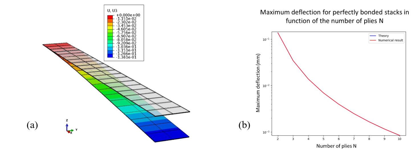
Fig 12. Result of cantilever bending simulation performed on a two-ply perfectly bonded stack (CSS8+M3D4) (Deformation scale factor: 10) (a). Comparison of theoretical and numerical maximum deflection in function of the number of plies for perfectly bonded stacks (b). Each ply is modelled according to the embedded element approach using membrane M3D4 and solid-shell CSS8 elements.
From experiments, Bouquerel [5] defines a bending moment/curvature relationship for a N-ply stack of HiTape® reinforcements (equation (6)).

Using this relation, we are able to calculate the bending stiffness for a N-ply HiTape® stack. To properly compare numerical and theoretical values for HiTape stacks, we consider a curvature 𝜅 equal to zero to stay in the small deformations hypothesis. It appears from this that the theoretical bending stiffness of bonded stacks is much larger than the one determined for a HiTape® stack from equation (6) (Fig. 13). As explained earlier, this difference comes from inter-ply phenomena that are not considered here for perfectly bonded stacks.
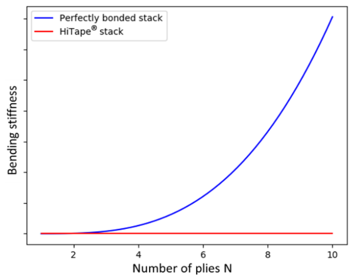 Figure 13. Evolution of the bending stiffness relatively to the number of plies for a perfectly bonded stack and a HiTape® stack (the y-axis has been voluntarily withdrawn for confidentiality reasons)
Therefore, cohesive elements are introduced between every ply of the stack to model these inter-plies phenomena. Regarding L. Bouquerel’s experimental results [5] [6], a proper set of parameters is used to describe the separation/traction frictional law of cohesive elements. Cantilever bending of N-ply stacks, with cohesive elements, have been studied. Numerical results of maximum deflection are compared to theoretical values, issued from equation (6), for a HiTape® N-ply stack (Fig. 14), and results in errors 𝜀2 = 8,81%, 𝜀3 = 0,3% and 𝜀4 = 2,92% for two, three and four plies respectively. However, the error increases with the number of plies. For example, considering a twenty-ply stack, the maximum deflection error reaches 22,4%.
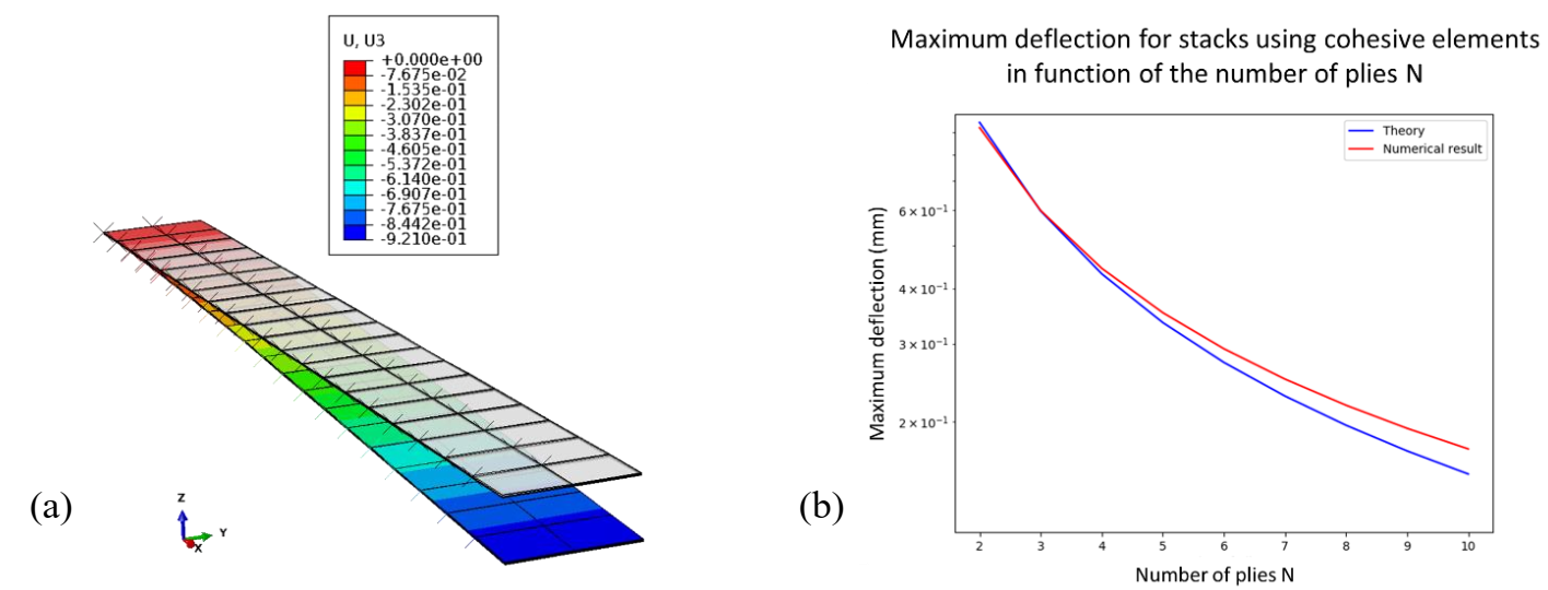 Fig 14. Result of cantilever bending simulation performed on a two-ply perfectly bonded stack (CSS8+M3D4) (Deformation scale factor: 10) (a). Comparison of theoretical and numerical maximum deflection in function of the number of plies for perfectly bonded stacks (b). Each ply is modelled according to the embedded element approach using membrane M3D4 and solid-shell CSS8 elements.
5 Conclusions
In this paper, we propose a new approach to simulate the aeronautical HiTape® parts forming process. The objective is to obtain an industrial-oriented simulation model allowing defects prediction and optimisation of the double-diaphragms process. Characterization of the behaviour of HiTape® have been conducted by Bouquerel et al.[5] [6] and is used in this study. Various methods have been presented to model a HiTape® stack, and its remarkable properties, and have been combined in order to obtain a global FE model. The embedded elements method [14] [15] [16] has been proposed for the representation of the decoupling of traction and bending behaviours of the ply. To avoid any locking phenomena that can appear for FE slender structures, particularly in bending dominated situations, solid-shell elements [8] are employed. The large deformations of stacks during forming requires an adapted constitutive law. L. Bouquerel [5] has determined an invariant-based formulation of a hyperelastic potential for HiTape® plies we will used for next simulations. Finally, modelling of the inter-ply areas represents a real issue. The selected approach is based on frictional cohesive zone element [22], allowing softening of the overall bending stiffness of the of the whole structure. The proposed global model for N-ply HiTape® stacks has been validated, through simulations, with N from 2 to 10, but still needs to be improved for thicker stacks.
