1. Introduction
Advantages properties of fiber reinforced polymers (FRPs) have promoted their wide usage in several applicative sectors, ranging from aerospace, automotive, through to naval and construction industries [1-3]. Advanced FRPs are multi-phase materials made of continuous reinforcing fibers, oriented in one or more specific direction, embedded within a polymeric matrix. In the recent years, the increasing request from industry of lightweight multi-materials components, pushed the scientific community to devote remarkable efforts towards the manufacturing, modeling, and processing of high-quality fiber reinforced composites [4-9]. One of the main drawback in FRPs is related with the poor surface properties. Nevertheless, recently, the development of manufacturing technique to metalize FRPs, is providing them interesting surface properties [10-12]. Despite of high specific strength and stiffness, corrosion resistance, and design flexibility, FRPs are affected by some drawbacks limiting their further application. As a multi-phase material, FRPs have an anisotropic behavior dependent on reinforcements’ orientation. This leads to excellent performance under longitudinal loading, but scarce (matrix dependent) behavior in case of transverse loading. In most lightweight composites, matrix is constituted by polymeric materials, both thermosetting or thermoplastic resins, whose main roles are to keep together the fibers, transfer and distribute loads, and protect them from the atmospheric agents. To improve the material properties and reduce anisotropic behavior, the most used strategy is to lay the fibers plies in different directions.
Hand layup has been the earliest manufacturing technique used for shaping composite products [13]. Also classified as a no-industrial process, this technique offers the advantage of low-cost suitability for the production of small batches. But as a manual process, the hand layup carries all the problems lead by the operator actions. From a quality point of view, this means that it is impossible to reach a standardization of all the pieces produced [14]. To improve the repeatability and reduce the human intervention, other manufacturing processes have been developed such as, among others, liquid composite molding, pultrusion, filament winding. Through the years, most of the manufacturing processes to fabricate fiber-reinforced composite products are based on conventional techniques such as the autoclave. But the demand for automation is rapidly increasing in the industry in order to achieve lower costs, repeatability, and reduction in material scraps [15].
Recently, the application of robotic manufacturing to composite layup led to the development of an innovative process, namely automated composite layup [15], based on the replacement of human operations by one or more opportunely programmed and eventually collaborative robots [16]. Robots need specific instructions which are mainly divided in two parts. The former regarding to the tool paths generation in geometric terms: the system receives information about the mold shape, the tool, the sequences and the strategies to apply, and it processes them providing an ordered set of cartesian coordinates with their orientations, which the tool must follow as output. The latter, concerning the generation of the trajectory from the kinematic-dynamic point of view, where the system works on the output of the first step, associates them an equation of motion and any boundary conditions about the specific position, orientation, speed and acceleration of the various axes of the robot [17]. Nowadays, the industry is evolving again, with the increasing introduction of autonomous production systems, based on the "Internet of things" and "Internet of service". Industrial robots, identified as the "key drivers" of industry 4.0, have evolved considerably in the last decades, become more productive, flexible, versatile, safe and collaborative, and thus generating an unprecedented added value in the entire industrial system. The "smart" factories, which going to be the core of Industry 4.0, will rely on information and communication technology for the evolution of the production line, but also of the supply chain, which will lead to a much higher level of automation and digitization. This is possible thanks to systems that are capable of self-optimizing and self-configuring, equipped with artificial intelligence, to complete complex tasks, in order to offer far superior efficiency and better-quality goods and services [18].
In this context, the present study aims to the implementation of a computational protocol and tools for composite manufacturing by automate layup process. In particular, the automated layup of dry fiber layers on a complex molds shape by robotic system. The molds shapes include different geometric features which require the adoption of different laying techniques, as shown in Figure 1.
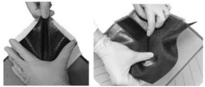 Fig. 1. Representative examples of distinct manual layup techniques.
The study of these techniques has led to the development of a specific end-effector, appositely designed to replicate the movements of the operator during the manual layup process. Moreover, different strategy and different tool paths have been investigated.
2. Materials and Methods
Discretization of mold geometry
The instructions taken by the robot are points coordinates and equation of motion that the tool has to follow. There are two strategies to achieve this aim: surface recognition by photogrammetric methods or by importing a CAD model of the mold. Even though the second method is not accurate as the first, because it's referring to a perfect geometry given by the software CAD model and not affected by manufacturing defects, it has been here adopted due to the simplification in surface elaboration and discretization. After choosing the cloud point processing method, the CAD file was exported in Standard Triangulation Language format (usually known as .stl format), and starting from it, the coordinate matrix was generated of the mesh nodes.
The tool chosen for the grid points generation was "Gmsh", an open-source software CAE widely used for FEM analysis, and to elaborate the cloud of points and program the tasks of the robotic arm and its end-effector, the software used has been Matlab.
A random positioning of the points of the mesh has been preferred due to the higher efficiency of the algorithm to search for the nodes as close as to the ideal crossing points generated for trajectory.
Being that several mold geometries could be processed, which could include different surface types, to increase the versatility of the program code, it is important divide the mold surface into elementary entities better managed by the software.
In this particular case under study, the complex mold surface has been divided into elementary surfaces identified in: flat, oblique, spherical, and fittings.
The choice regarding the chronological succession of the surfaces to be processed is obviously left to the operator, who can arbitrarily plan the process depending on the needs mainly concerned the mold shape and complexity.
Definition of the waypoints
The elaboration of the trajectory followed by the end-effector follows different steps as showed in Figure 2. The process starts from the coordinates’ identification of the ideal points belong to the trajectory, which have been subsequently compared with the real points presents on the mesh given by the discretization surface to identify the real waypoints. Working on each point coordinates X and Y separately, the real point will be considered if the distance between it and the ideal point is smaller than a certain quantity that identifies tolerance range specified by the user: smaller is the distance, higher will be the density of the points and higher will be the elaboration time by the processor.
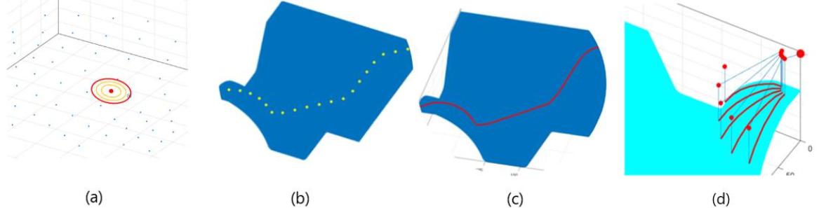
Fig. 2. Trajectories and routes identification steps: (a) real waypoint identification; (b) waypoints of a single route; (c) different waypoints interpolation for different geometry shape; (d) multiple routes and robot tasks generation.
In case there is no point inside this range, the distance will be increased of a small delta set in the algorithm, until a point will enter in the range as close as possible to the range requested from the user. Collected the coordinates of the real waypoints, the program interpolates the best approximate of the requested trajectory, or by increasing the number of considered points between two waypoints, or by interpolating the trajectory between using the mathematical models (linear, circular, cubic, spline) deemed more suitable by the operator. Obviously, the using of one method does not exclude the other and the operator is responsible to define the strategy deemed most relevant.
Added to the information regarding the points coordinates, the end-effector should be always perpendicular to the surface to be processed. To this aim, the Frenet-Serret triad, also known as TNB, was defined for each points of a curve three unit-vectors, called Normal, Binormal, and Tangent. Two of them are on the same plane of the osculating circle corresponding to that specific point, and the other one is always perpendicular to that plane. The TNB triad has been also implemented with the H. Gugghenheimer algorithm to avoid that normal and binormal vectors twist around the tangent as showed in the Figure 3 [19].
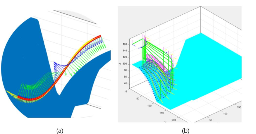
Fig. 3. Frenet-Serret triads: (a) showing the problem of the normal and binormal vectors twist around the tangent; (b) showing the result obtained after Gugghenheimer algorithm implementation.
Robot arm information
In addition to the information regarding the trajectory points, it is required also the configuration of the robotic arm and its end-effector. These information are included in the URDF which uses the XML standard to describe a robot which includes kinematic and dynamic behavior, visual representation and collision model. As showed in the Figure 4a, the robot description consists of a set of elements and of joins that connect them.
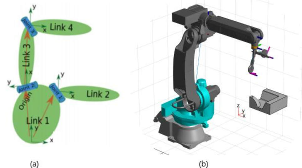
Fig. 4. (a): example of a robotic arm URDF model; (b) the robotic arm during a simulation test in Matlab.
The URDF model is then codified as a "Rigid Body Object" suitable for further handling in Matlab environment. The movements of the robotic arm are subsequently translated in PDL2 language, which can be understood by the manipulator control unit.
Given the significant number of parameters to set, entering by keyboard the inputs directly in the Matlab Command Window is quite laborious. Thus, to provide an easier handling of the software an interactive graphical interface, allowing users to easily define and modify all parameters, was implemented using the "App Designer" tool integrated into Matlab environment.
An exhaustive simulation of the robot movements is also essential in order to properly design the machining. The simulation has been performed in Matlab using the information contained int the URDF model and the .stl file (Figure 4b).
3. Results and Discussion
The first outcome of this study is the identification and processing of the mesh, starting from the 3D representation of the mold. The implemented algorithm proved to be effective in processing the geometries defining the mold surface. This capability is essential for all the further processes design and for their industrial applications since it allows users to process distinct and complex shapes. Although the surface recognize has been manually driven for this specific mold geometry, the algorithm can guarantee to the operator the freedom to define the sequence of the various process tasks of each mold's portions also establishing their sequence, like a traditional CAM software. Another result, which also opens considerable further developments, is represented by the generation of a number of ideal waypoints established by the user, which can describe a corresponding number of routes side by side. As already mentioned, the definition of these ideal points is the basis for the choosing and acquisition of those mesh points, which will become part of the tool path.
To make the robotic layup performed during this study as close as possible to the hand layup performed by the laminator, a specific end-effector has been carried out composed by three terminals: a cylindric wheel for a flat or oblique plane, a filleted wheel for fillets and narrow parts, and a small punch for the angles and vertexes (Figure 5).
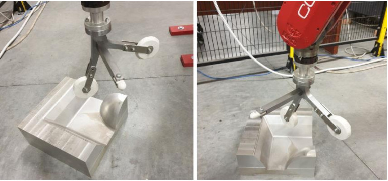 Fig. 5. The end-effector realized specifically for this study
Starting for a single route generation, numerical challenges were given by the management and storing of the various sets describing the routes. For this purpose, the triple indexing arrays have been useful, since they provide remarkable simplicity in data management, with a relatively low computational cost. Subsequently, the algorithm has been strengthened giving the user the possibility to set the different combining modes of the waypoint that define the various tool path. Parallel and polar placement path modes have been successfully implemented (Figure 6).
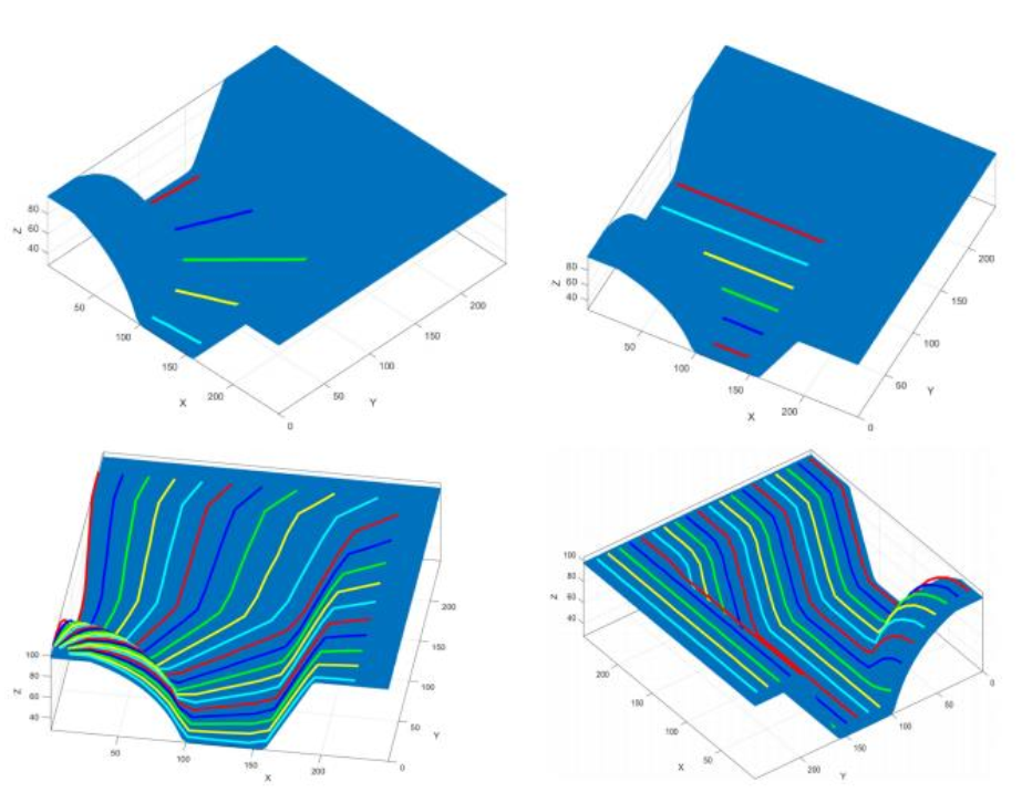 Fig. 6. Path placement definition: on the left picture side is showed a radial strategy; on the right side a parallel strategy.
Furthermore, the implemented code successfully recognizes the morphology of surfaces being processed, adapting the movement of the robot and of the end effector accordingly (Figure 7). This function, developed thanks to the subdivision the mold surface into several elementary portions, is essential to prevent the tool from getting in contact with unwanted surface portions during processing. Noteworthy, the algorithm effectively connected the generated multiple tool paths, creating a single layup movement, constituted by active steps (red curves and lines in Figure 7) and rapid passive movements (blue lines in Figure 7).
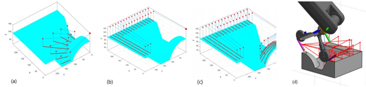
Fig. 7. Tool paths and tasks generation with different length and with the stopping points: (a) showing radial routes strategy; (b) parallel strategy; (c) example of multiple-tasks generation.
The code implemented with Matlab has been also compared with one of the most common used simulation software, RoboDK. Even if RoboDK software is very user friendly with an intuitive graphical interface, in which no programming skills are required, when the need to program a specific path for the end-effector occurs, it offers a number of a predefined tasks for the robot, which easy allows users to program the robot’s movements during the process according with the surface to be processed. In the case under study, with a complex mold shape, it is tough to find a predefined task that perfectly fit the surface geometry, forcing the user to adapt the strategy to use with the available movements offered by the software. In Figure 8, some of the strategy available to treat the different kinds of geometry present in the mold surface under study.
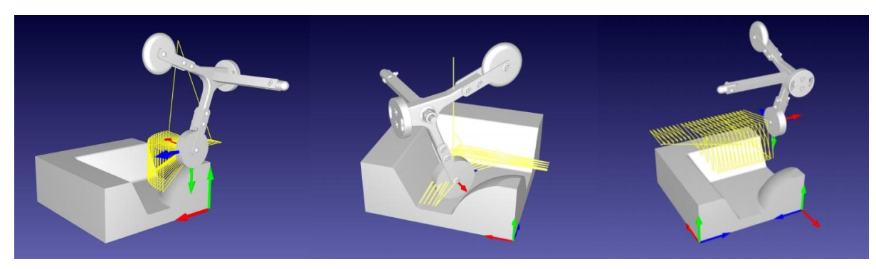 Fig. 8. Representative examples of some strategy available in RoboDK.
Programming in Matlab language is more difficult and requires some programming knowledge, but users have the possibility to program freely a paths and tasks, moving the end-effector trough routes closer to the manual processes, and to treats more than one kind of surface (flat, spherical, oblique) in one task. This offers to users the possibility to choose the strategy of layup which better fit the strategy used by manual laminator.
4. Conclusions
In this work a numerical tool for the definition of the deposition strategies for automated composites layup has been proposed and tested.
Starting from the discretization of the mold surface, assumed as input data, the implemented algorithm allows the user to identify elementary sub-surfaces and then to create the path for the robot and the end effector by the opportune definition of waypoints and the computation and adjustment of the Frenet-Serret triads along the trajectory, also providing the possibility to create a unique task for the robotic arm including all the passive movements.
The proposed code has been tested simulating the automated layup process on a complex mold, by means of a specifically designed end-effector and comparing the programming steps and outcome with the same operation conducted using a commercial package. It emerged that the implemented tool is more versatile if compared with RoboDK, offering the opportunity to create and connect paths, even if more programming skills are required. The computed tasks for the end-effector successfully approximate the manual strategies used by professional laminators.
