1 Introduction
Tailored blanks are a good solution for the increasing need expressed by the automotive and aerospace industries for efficient lightweight components [1]. The tailored blanks are developed to optimize the performances by combining different shapes, thicknesses, surface properties, or materials. Tailored blanks manufacturing is based on sheet cutting, flexible plastic forming, and advanced welding techniques [1–5]. The flexibility and the potentialities of this class of components provide the designer with countless solutions to increase efficiency and develop sustainable products [6]. It is clear that the design and manufacturing of tailored blanks require an approach based on the integration of production processes, materials, operations management, and quality assessment tools [7–10].
Among the welding methods, friction stir welding (FSW) attracted the attention of many researchers due to the high quality and mechanical performances of the produced joints, and to the flexibility of the process [4,11,12]. FSW is a solid-state welding process, meaning that the welded sheets do not reach the melting point and no melted alloys are involved. FSW is based on the solid intermix of the crystal lattice of separate sheets [13]. The intermix is achieves by the action of a rotating stirring tool. The stirring tool typically is constituted by a cylindrical body, equipped with a cylindrical or conical pin on its top surface, even if in some cases, depending on the joint configuration and the materials treated, the pin can assume a different shape [14]. The tool rotation and displacement are controlled by common CNC systems. The rotating tool penetrating and stirring the sheets generates a high heating effect. The consequent increase in temperature induces a local softening of the metallic alloys and promotes the plastic flow [15]. The rotating tool advances according to the welding line to be produced. As a consequence, the tool can be considered, under the thermal point of view, as a heat source moving along a predefined path. It is clear that, when the tool advances, the materials are subject to a fast temperature decrease driven by the contact with air at environmental temperature [16]. The plastic flow is driven by the tool rotation and advancement. Considering a section orthogonal to the tool advancing direction, an advancing zone and a retreating zone can be defined. On the advancing side, the rotation is in concordance with the tool advancing speed, while on the retreating side the two velocities are in opposition. The tool action promotes the materials’ plastic flow from the retreating side to the advancing side. Moreover, the tool plunging effect induces upward materials plastic flows [17]. The combination of fast heating, cooling down and the aforementioned plastic flows determine the typical microstructure of FSW joints composed of a nugget zone (NZ), a thermomechanically affected zone (TMAZ), a heat affected zone (HAZ), differing by the base material (BM) in the grain size and shape, and, therefore, in the mechanical properties [14].
FSW blanks are often shaped by adopting the single point incremental forming (SPIF) process [18–20]. It is a moldless process based on the local action of a forming tool driven by common CNC systems or robotic arms [21]. SPIF demonstrated higher formability compared to the conventional sheet forming methods [22]. A full description of the process, adopted equipment, performances, and limitations has been provided by Duflou et al. [23]. The presence of different zones characterized by different mechanical properties clearly affects the forming process. The adopted welding parameters determine the properties and the extension of NZ, TMAZ, and HAZ, and, therefore, the plastic behavior of the entire tailored blank. FSW joints have demonstrated in previous works high formability, in some cases even better than the BM one [9].
The present work aims to compare the mechanical behavior of FSW aluminum AA 6082 blanks welded adopting different tool rotational speed (TRS) and welding speed (WS) in butt joint configuration. According to the procedure described in previous works [7], the plastic behavior of the joints has been evaluated based on the microhardness of the cross-section. The phenomenological Swift law has been adopted to describe the evolution of the flow stress. The models, implemented using the ABAQUS suite integrated with several user subroutines, aim to simulate the stress-strain response in the tensile testing of coupons collected from FSW blanks transversally to the welding line direction.
2 Materials and Methods
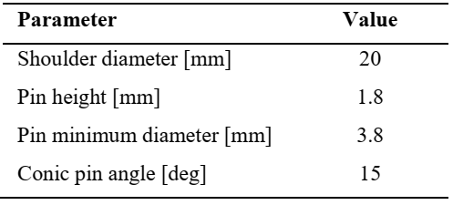
FSW butt joints of 2 mm thick sheets in aluminum alloy AA 6082 have been experimentally produced using a FAMUP MCX 600 CNC machine equipped with an HSS tool. The FSW toolpath has a length of 200 mm. The main parameters describing the tool geometry are reported in Table 1.
Table 1. Geometric parameters of the FSW tool.
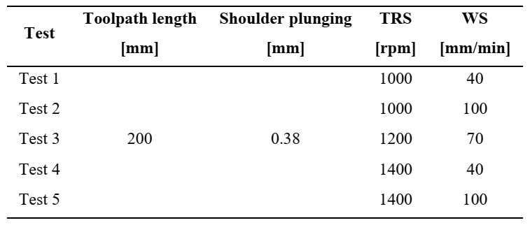
The welds have been produced adopting the process parameters reported in Table 2.
Table 2. Chosen process parameters.
Samples have been collected from the realized joints, embedded in epoxy mounting resin and polished, in order to observe the cross-section and evaluate the microhardness field. The micro-indentations have been done using a Leica VMHT-auto microhardness tester, using an indentation load of 100 g. The indentations have been performed on each sample along a 30 mm long path having his middle point corresponding to the center of the NZ.
The microhardness values have been used to model the plastic behavior of the welds, according to the procedure previously published [7]. Fig. 1 illustrates the sample modeled in ABAQUS, focusing on the discretization, and schematically representing the applied boundary conditions.
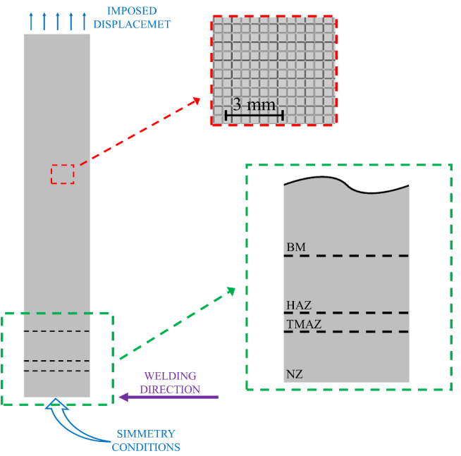 Fig. 1. Schematic representation of the implemented numerical model.
The modeled sample geometry is illustrated in Fig. 1. It represents a coupon 220 mm long and 20 mm large, cut transversally to the welding direction. In order to reduce the computational effort, half of the sample has been modeled and symmetry conditions have been applied to the symmetry boundary, corresponding to the centerline of the welding toolpath. An imposed displacement has been applied on the extreme edge of the sample, as described by the blue arrows in Fig. 1. Since in the problem addressed in these simulations the thickness of the samples is negligible when compared to the sample length and width, the coupon has been modeled as a planar surface and discretized by S4R shell elements, having 5 integration points along with the thickness. The elements, visible in the magnified view reported in Fig. 1, have initially square shape with dimensions 0.5 mm long.
The elastoplastic mechanical behavior has been modeled adopting Swift’s law, defined in Eq. 1:

where σY is the flow stress, ε-p represents the strain, while ε0 is defined by Eq. 2

In these two relations, the symbols k, η, and σ0 are parameters depending on the adopted material. The calibration of these parameters has been performed accounting for the microhardness results [7]. According to the microhardness distributions measured, the NZ has been modeled with constant properties. In correspondence with the TMAZ, the microhardness sharply drops up to a minimum, located at the boundary between the TMAZ and the HAZ. In the HAZ, the microhardness linearly increases from the minimum value to the BM value. The microstructure in the BM zone has not been modified by the process, therefore the microhardness is constant in that zone. Therefore, in NZ, the mechanical parameters k, η, and σ0 have been modeled as constants, while in TMAZ and in HAZ, they were linearly depending on the distance from the welding centerline. In particular, the yield stress decreases in the HAZ as the distance from the centerline increases. Conversely, in the TMAZ the yield stress value increases with the distance from the centerline. In the BM, which is the widest zone of the sample, the material properties are constant.
The described mechanical model has been coded in Fortran language in a user material (UMAT) subroutine.
3 Results and Discussion
Fig. 2 shows the microhardness profiles acquired on the cross-section of the produced FSW joints.
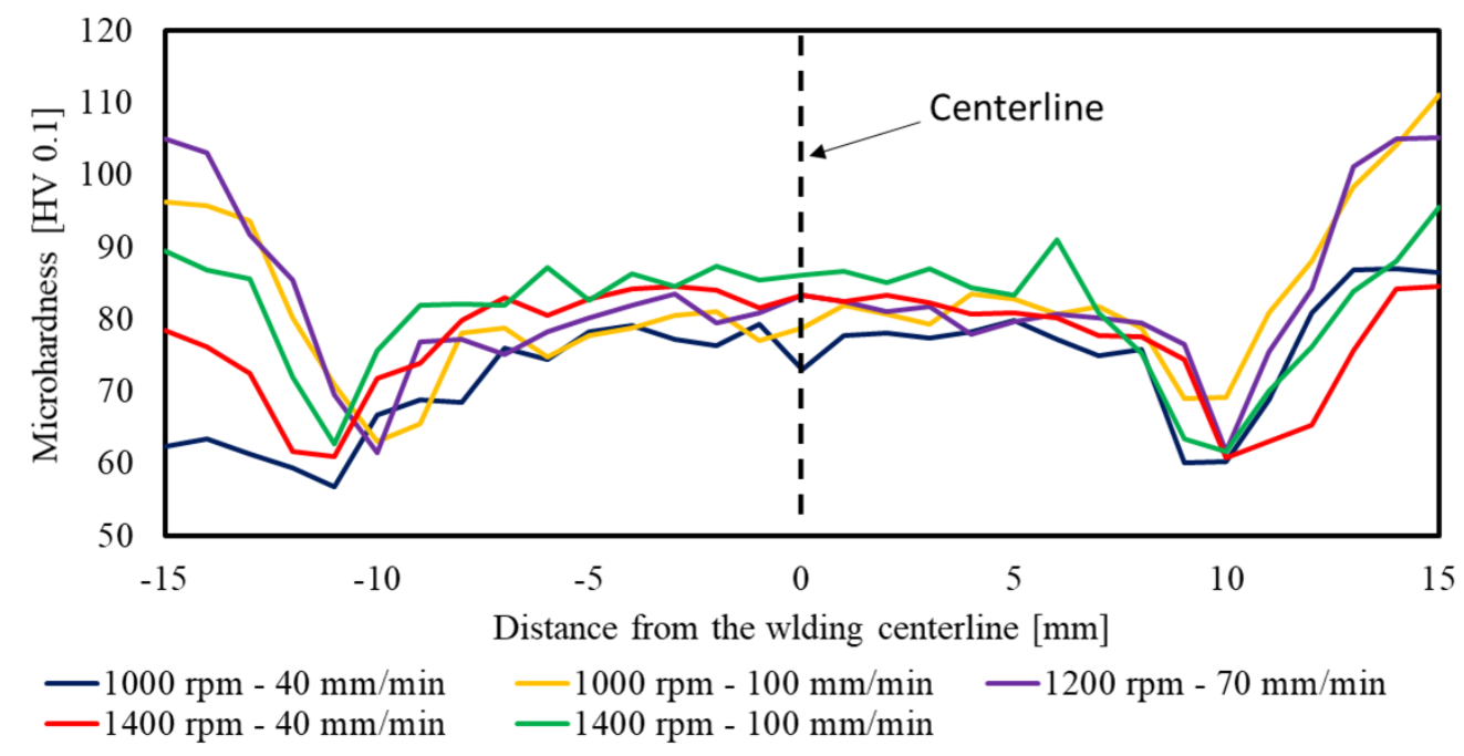 Fig. 2. Microhardness profiles acquired on the cross-section of the produced joints.
The FSW process has determined a decrease of the microhardness, from the BM value (110 HV100) to the profiles shown in Fig. 2. In general, the microhardness profiles exhibit qualitatively similar behavior. In the NZ, the microhardness oscillates around a constant value. The TMAZ corresponds with the sharp reduction of the microhardness. The minimum detects the boundary between the TMAZ and the HAZ. The numerical values of microhardness are reported in Table 3.
Table 3. Microhardness values measured.
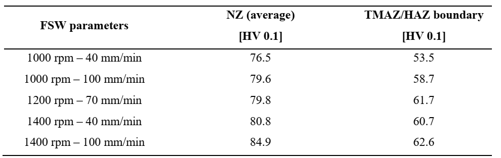
The results reported in Table 3 evidence that the higher TRS and WS provokes higher microhardness in the NZ. Indeed, the heat produced by the process depends on the stirring action and on the friction between the pin shoulder and the blanks. Therefore, higher TRS generates higher heat and, consequently, higher temperature. The hardening is related to the cooling rate, which depends on the temperature reached during the stirring phase and on the WS. Indeed, the higher the WS is, the faster the heat source moves away.
The contour plots reported in Fig. 3 illustrate the numerically computed stress and strain distributions relative to the simulation of the tensile test on the sample produced using TRS of 1000 rpm and WS of 40 mm/min, as a representative case.
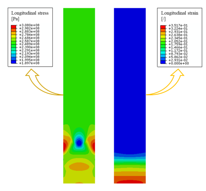 Fig. 3. Longitudinal stress (left) and strain (right) distribution evaluated for the case TRS=1000 rpm, WS=40 mm/min.
The distribution of tensions and strains reported in Fig. 3 evidence how the variability of the properties due to the FSW effects affects the mechanical behavior of the coupon. In particular, the difference in the yield points between the different zones determines a remarkable difference in the plastic strain. The applied displacement provokes severe plastic deformation at the NZ and the TMAZ. Indeed, these two zones are characterized by low yield stress. Conversely, in the BM, even if the tension reaches values up to 260 MPa, the yield (275 MPa) is not reached, and consequently, the final longitudinal strain is negligible if compared to the deformations in the NZ. This behavior is described by the stress-strain curves relative to 4 points picked along the central axis of the coupon in the NZ (at 4 mm from the centerline), in the TMAZ (at 9.5 mm from the centerline), in the HAZ (at 15.5 mm from the centerline) and in the BM (at 50 mm from the centerline), depicted in Fig. 4.
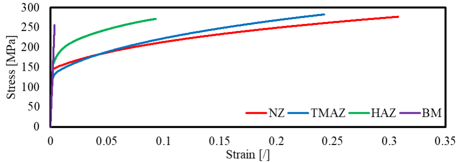
Fig. 4. Stress-strain behavior of the 1000 rpm – 40 mm/min coupon in four different points: NZ (4 mm from the centerline), TMAZ (9.5 mm from the centerline), HAZ(15.5 mm from the centerline), and BM (50 mm from the centerline).
It is worth noticing that the NZ plastic behavior presents a remarkably lower slope if compared to the TMAZ and the HAZ. This mechanical behavior agrees with experimental pieces of evidence reported in the scientific literature [14]. Indeed, from a microstructural point of view, the NZ experiences full recrystallization, which promotes the plastic flow. Conversely, the TMAZ and the HAZ experience a severe heat treatment which reduces the grain size and thwarts the crystal lattice sliding.
Fig. 5 depicts the stress-strain profiles in the five conditions simulated, evaluated in two geometrical points of the coupon axis: In the NZ (dashed lines) at 4 mm of distance from the centerline and on the boundary between TMAZ and HAZ (solid lines).
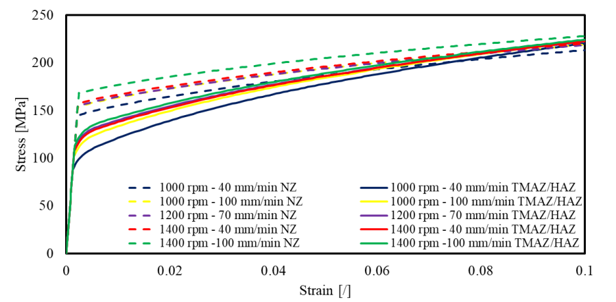 Fig. 5. Stress-strain behavior of the five modeled coupons picked along the coupon axis in two different points: in the NZ at 4 mm from the centerline (dashed lines) and the boundary between TMAZ and HAZ (solid lines).
It is evident from the curves that the samples realized at higher TRS and WS exhibits a higher yield point, due to the higher microhardness. Moreover, comparing the plastic behaviors of the different coupons simulated, it is evident that higher TRS and WS imply lower slopes of the stress-strain plastic curves.
4 Conclusions
This article presents a numerical approach to model the elastoplastic behavior of friction stir welded blanks of aluminum alloy AA 6082 in butt joint configuration, produced to be shaped by single point incremental forming. The material’s properties have been assigned to the samples based on the microhardness of the cross-section experimentally evaluated. The manuscript highlighted the following aspects:
· In friction stir welding processes, the microstructure, and as a consequence, the microhardness depends on the adopted process parameters. In the tested conditions the weld cross-sections present a microhardness ranging between 75 and 85 HV 0.1, remarkably lower than the 110 HV 0.1 of the base material. The joint produced using the highest TRS (1400 rpm) and WS (100 mm/min) presents the highest values of microhardness.
· The FSW operative parameters affect the elastoplastic behavior as well. The grain size variability along with the coupon, due to the stirring, the recrystallization, and the thermal cycle related to the FSW, determines gradients of properties in the produced joints. The yield stress and strain and the plasticity present remarkably different behaviors in the different zones of the sample.
