1 Introduction
Ultra-high strength steels are used in various industrial applications, such as vehicle and mobile crane manufacturing, where high strength is required but low weight is also especially beneficial. As a relatively flexible, cost-effective, and quick sheet-metal forming method, air bending is commonly used in these applications. The flexibility of air bending stems from the ability to achieve a continuous range of different bend angles without changing tools by controlling the punch displacement. The downside of UHSS is their limited bendability because of their generally low fracture strains and inability to sustain large amounts of local deformation.
Bendability is usually expressed as the minimum radius Rmin around which a given material can be bent to a 90° angle without surface defects appearing. The Rmin for ultra-high strength steels tends to be around 1 to 4 times the sheet thickness. However, bending with large radius punches introduces other challenges and disadvantages such as increased required bending force, larger springback and a tendency for a loss of contact between the sheet and the punch nose. In this phenomenon, also known as “multi-breakage”, the inner radius of the sheet becomes smaller than the punch radius and the loading scheme changes from 3-point bending to something akin to 4-point bending [1,2]. Multi-breakage and severe punch-sheet separation has been previously associated with a flat-top (or “nut-like”) bend geometry, in which the outside surface of the bend becomes flat at the centre [3–6]. Multi-breakage also affects springback and bend allowance, and the decrease of the inner radius may lead to higher strains than expected. Understanding of the phenomenon, its causes and effects is therefore essential for effective utilisation of large radius bending and bending of UHSS in general.
Multi-breakage (a.k.a. gap formation, loss of punch-sheet contact, punch-sheet separation, punch detachment, punch-sheet-liftoff etc.) in bending has been known as a phenomenon for a long time. However, research on the topic has been relatively scarce, and the varying terminology has made literature surveying on the topic quite difficult. Various analytical and semi-analytical models have been developed throughout the years for calculating springback, bend allowance, bend shape, bending forces, deformation etc. in air bending based on the tool geometry and material properties [7–16]. However, most of the models found in literature choose to ignore the multi-breakage phenomenon and its effects due to the convenience of the wrap-around assumption. This assumption can lead to significant errors in cases where multi-breakage commonly happens, such as large radius bending of UHSS.
Pourboghrat and Stelson [9] presented a model for predicting the nonuniformities in the punch-sheet contact and gap formation, i.e. multi-breakage. Larger Rp/t (punch radius to sheet thickness) ratios were shown to contribute to earlier gap formation, and higher friction coefficients were shown to delay the gap formation by increasing the tangential tension in the sheet. Punch friction was found to affect the gap formation more than die friction. Similar results on the effect of friction on multi-breakage and gap formation were also obtained in an FE-simulation by Burchitz [17]. Vorkov et al. [2,15,18] studied the contact point shift in multi-breakage and its effects on the moment distribution, bending force, springback and bend allowance. Ruoppa et al. [19] measured the inner sheet radii and punch-sheet gaps among other cross-sectional measurements in large radius bending of UHSS to 90° angles.
The aim of this study is to investigate the bendability of three UHSS grades utilising Digital Image Correlation (DIC) for measuring the strain distributions on the outer curvature. Likewise, the differences in the extent of multi-breakage and the bend shapes are studied, and these observations are correlated with the findings from the bending force and strain measurements and tensile tests. Bending tests with DIC strain measuring have been previously done by many authors [6,20–25], some of which have also measured the strain evolution during bending [20,23,24].
2 Experimental setup
Three thermomechanically rolled UHSS grades are tested in this study: 700, 900 and 1100 MPa grades. Table 1 provides the tensile properties of the materials, along with the minimum bend radius (to 90° angle) and die width (Wd) provided by a steel manufacturer for corresponding steel grades. The tensile data was obtained with ISO 6892 compliant specimens (straight section of 6 × 10 × 45 mm3) and speeds of 0.0025 1/s (to yield point) and 0.008 1/s (after yield point). The tensile tests were done both longitudinally (0°) and transversely (90°) to the rolling direction. The 0° and 90° tensile test orientations correspond to the transverse (TD) and longitudinal (RD) bend orientations, respectively.
Table 1. Mechanical properties and minimum bending values of the investigated materials. The yield strength (Rp0.2), ultimate tensile strength (Rm), uniform elongation (Ag) and total elongation with 40 mm gage length (A40) were obtained from tensile tests. The minimum bend radius to 90° (Rmin) and minimum die width (Wd) were provided by a steel manufacturer.
|
Material |
t (mm) |
Rp0.2 (MPa) |
Rm (MPa) |
Ag (%) |
A40 (%) |
Rmin (to 90°) |
Min. Wd |
|
700 (0°/90°) |
6.04 |
784/811 |
867/896 |
5.7/4.9 |
18.0/15.7 |
1 t |
10 t |
|
900 (0°/90°) |
5.99 |
983/1030 |
1054/1128 |
3.6/2.4 |
14.8/10.7 |
3 t |
12 t |
|
1100 (0°/90°) |
6.04 |
1127/1133 |
1157/1176 |
4.8/4.9 |
16.1/14.9 |
3.5 t |
14 t |
The materials are tested in both longitudinal (RD) and transverse (TD) orientations, referring to the bend axis being either parallel (RD) or perpendicular (TD) to the rolling direction. Rectangular specimens with width (bend length) of 100 mm and thickness of 6 mm were bent in room temperature using a Zwick 100 kN universal tensile test machine with purpose-build tools. The setup allows measuring of bending force, punch stroke and most importantly, continuous DIC measurement throughout the test through the openings in the lower tool. The punch is also stationary in this setup to ensure that the measurement area stays in focus throughout the tests. As the punch is stationary, the necessary punch stroke is produced with the lower tool moving upwards at a speed of 1 mm/s. For this study, punch radius of 12 mm and a die shoulder radius of 6 mm were used, with a 110 mm gap (die width) between the centres of the shoulders. The test setup and DIC camera positioning are presented in Figs. 1a and b. More information of the test setup can be found in Ref. [24].
The specimen width was chosen small enough to not exceed the force limit of the machine but large enough to ensure plane strain condition at the centre of the bend. The bending force is expressed as force per width (N/mm) to compensate for the small variation in the specimen widths. The punch stroke data was used to calculate the bending angles throughout the test according to ISO 7438 [26]. The punch stroke data was adjusted for the vertical elasticity of the setup (111.4 kN/mm) and play in the tools/sheet at the start (0.15 – 0.20 mm), determined by the Z-displacement measured with the DIC.
The DIC-system used for measuring deformation on the outer surface of the bend was Strainmaster by Lavision with a camera resolution of 2456 × 2058 pixels and an imaging frequency of 2 frames per second. The specimens were painted with a black-and-white speckle pattern to enable accurate tracking of points on the measured surface by the DIC-software. The effect of paint peeling was minimised by cleaning the surface thoroughly before painting and by conducting the test as soon as possible after painting so as not to let the paint dry too much and lose its elasticity. The displacement data of the tracked points is then used by the software to calculate the deformation on the measured surface. The facet size used for the DIC strain measurement was 15 × 15 pixels, with a step size of 5 pixels. The image scale was approximately 20 pixels/mm. Two filters were applied for the strain measurement data: an outlier filter for deviations over 4 times from the average in an 11 × 11 pixel area and a second order polynomial smoothing filter over a 5 × 5 pixel area, with polynomial extrapolation used for filling up missing vectors. From the obtained strain maps, strain distribution graphs were extracted from three lines positioned at the centre of the bend at 10 mm intervals as pictured in Fig. 1c.
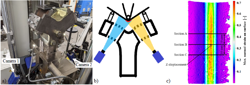
Fig. 1. (a) The test setup, (b) DIC camera positioning. and (c) the sections (A-C) and areas for the extraction of strain and Z-displacement measurements, displayed on a DIC-measured strain map of the 900 MPa grade in the longitudinal (RD) orientation at 90° bend angle
3 Results
Side view images of the bent specimens at 90° are provided in Fig. 2 and the strain distributions at 30, 60 and 90° bend angle along the section line B are presented in Fig. 3. It can be seen that the distributions are similar until 30° but start to differ as the bend angle increases further. The deformation in the 900 MPa grade keeps increasing mostly at the centre, while in the 700 and 1100 MPa grades, the deformation is spread out more evenly. Comparing the images in Fig. 2 to the distributions in Fig. 3, the relation between the different bend shapes and strain distributions can be seen clearly. In the 900 MPa grade, the deformation is concentrated in a very narrow zone in the middle and thus, the curvature change is also concentrated in the middle (Fig. 3b). Consequently, the inner radius of the sheet at the centre has decreased far below the punch radius, causing a pronounced gap between the punch and the sheet (Fig. 2b). The 1100 and 700 MPa grades can be seen following the punch more closely and the apparent small gap is mostly at the edge and caused by anticlastic curvature.
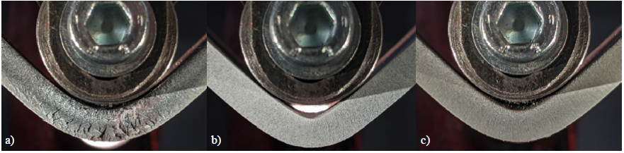
Fig. 2. Side-view images of (a) 700, (b) 900 and (c) 1100 MPa grades in the longitudinal direction (RD) at 90° bend angle
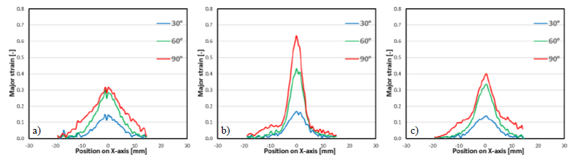
Fig. 3. Strain distributions at 30°, 60° and 90° extracted from section B of (a) 700, (b) 900 and (c) 1100 MPa grades in the longitudinal direction (RD). The X-axis positions of the datapoints are all from the start of the test.
The bending force measurements are presented in Fig. 4a and the development of the peak strains (average peaks of sections A, B and C) of each measured strain distribution relative to the bending angle are presented in Fig. 4b. The strain distributions all develop identically in the first 10 – 15° of the bending, as the loading schemes are identical (in 3-point bending), most of the deformation is still elastic and the elastic moduli of the materials are similar (200 – 220 GPa). After around 15 – 25° (5 – 10% max. strain) the different work-hardening properties of the steel grades start to show as the peak strain curves diverge.
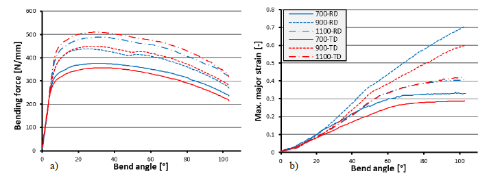
Fig. 4. The development of (a) the bending force and (b) the peak strain throughout the bending process
The Z-displacements of the outer bend surface are plotted in Fig. 5. The values were extracted from a 1 × 1 mm2 area at the centreline of the bend (as illustrated in Fig. 1c) and have been adjusted for the elasticity of the test setup (calculated as 111.4 kN/mm) and play in the setup at the start (0.15 – 0.20 mm). The displacement increases (i.e. the outer surface moves towards the punch) almost linearly between 10 – 50° for all materials. This is evidently due to thinning, as can be seen from the correspondence between the Z-displacements (Fig. 5) and the maximum strains (Fig. 4b) until the 50° bend angle. After around 50 – 55°, the displacements start to decrease, i.e. the outer bend surface starts to move away from the punch, indicating the start of punch-sheet separation (multi-breakage or gap formation). The start of multi-breakage can also be clearly identified from a turn in the peak strain curves of all steel grades at around 50 – 60° bend angle (Fig. 4b), and from a turn in the force curves at around 50 – 55° for the 900 and 1100 MPa grades (Fig. 4a).
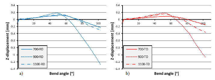
Fig. 5. Z-axis displacement of the centre of the outer bend surface in (a) longitudinal (RD) and (b) transverse (TD) bend orientations.
These observations can be explained as effects of the contact point shift in the multi-breakage phenomenon. Multi-breakage starts as the inner radius of the sheet decreases below the punch radius, which causes a gap between the sheet and the punch nose and a contact point shift away from the centreline. The contact points shifting towards the sides of the punch changes the moment distribution, which in turn increases the required bending force and restrains the strain localisation. The change seems more abrupt in the 900 MPa grade compared to the more gradual change in the other grades. This is understood to be a consequence of the localised strain distribution and the more pronounced multi-breakage of the 900 MPa grade. Presumably, the contact points move quicker and further apart when multi-breakage is more pronounced, resulting in a more abrupt change in the moment distribution compared to a case where the sheet follows the punch more closely.
The 900 MPa grade was also observed to form a flat-top or “nut-like” shape, unlike the other grades, due to the localised strain distribution and severe thinning at the centreline. Both 900 and 1100 MPa steels developed visible cracks or deep grooves on the outer surface, unsurprisingly, as the used punch radius is smaller than their minimum bend radii. The 700 MPa grade was deemed defect free.
Fig. 6 illustrates the negative correlation between the uniform elongation in tensile tests (Ag) and the peak strains in bending at 30°, 60° and 90° bend angles. The correlation seems good overall and improves as the bend angle increases. As Ag has been used as an indicator of global formability [27–29], the results suggest that the strain distribution in large radius bending is majorly affected by global formability. Consequently, global formability seems to be a significant factor in the bend shape and multi-breakage in large radius bending. Thus, the severe punch-sheet separation, thinning and “nut-like” shape of the 900 MPa steel are understood to be a consequence of its poor global formability (i.e. low Ag).
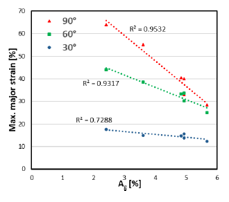
Fig. 6. Correlation of the maximum major strain in bending with the uniform elongation in tensile tests
4 Discussion
Bendability has been previously correlated to local formability (area reduction, fracture strains) [21,27,30,31], as it sets the limit for the highest local strain and curvature a sheet can endure without cracking. However, as demonstrated, global formability must not be ignored either as a factor in the bendability of a material since it affects the strain distribution, bend shape and multi-breakage, especially in large radius bending.
The minimum bend radius Rmin clearly does not provide enough information of the bending properties of the material, as seen by the contrasting behaviour between the 900 and 1100 MPa grades despite their similar Rmin values. A better alternative could be a combination of local and global formability measures, similar to what has been suggested by Hance [28] and Heibel et al. [27]. If factors for both the maximum local strain and strain distribution were provided, a more detailed description of the bending properties could be achieved, which would aid optimal material selection and tool choices for each specific case and application. For example, the smallest viable punch radius could be relatively easily estimated for all bend angles, not only 90°. The amount of punch-sheet separation and force increase due to multi-breakage could also be estimated, preventing accidental bottoming, and improving the maximum force estimations in large radius bending.
5 Summary & Conclusions
Air bending tests with DIC strain measurement were conducted on 700, 900 and 1100 MPa hot-rolled UHS steels. The strain distributions were found most localised in the 900 MPa grade, which was also deemed the cause for its severe punch-sheet separation (multi-breakage) and “nut-like” shape. A negative correlation was found between uniform elongation in tensile tests and the peak strains in bending, and global formability is understood to affect the bending properties of UHS steels significantly. Rmin as a measure for bendability was deemed insufficient, and better alternatives based on both local and global formability are called for.
