1 Introduction
Through-the-thickness reinforcements (TTR) provide mechanical connections between layers which improve the mechanical properties of the laminates. Several TTR technologies (such as 3D weaving, stitching, Z- pinning and tufting) have been proposed and studied in the literature [1-5]. Previously, tufting technology was only used for the manufacture of carpets, but currently, it has become one of the most effective technologies of the TTR. This technique is based on the One-Side-Stitching (OSS) technology. The tufting technology requires only one access to the preform and then continuity of the reinforcing thread throughout the laminate [1,2], making it ideal for reinforcing complex 3D structures. This process's advantage is that the loops are formed without generating tension within the preform when the thread is inserted.
Using the tufting technology to manufacture carbon composite parts by Liquid Composite Moulding (LCM) processes [6] enables the fabrication of high-performance composite materials for the aerospace and defense industries. As the first step of the LCM process, the dry preform should be shaped using a forming machine including punch, die and blank-holder components. This forming step provides the final shape of the complex parts where its control is based on the orientations and densities of the fibers and the minimization of defects that will influence the impregnation step (resin infusion) and impact the mechanical properties of the final part. Many input parameters substantially impact the forming stage, such as the architecture of reinforcement, punch shape, blank- holder pressure, the number of layers, etc.
The originality of this study lies in the experimental investigation of the deformability of (i) multi-layer 5HS carbon preforms with different stratifications (2 and 4 layers) at two blank-holder pressures (0.05 and 0.2 MPa) using a hemispherical punch, (ii) un-tufted and tufted preforms, and finally (iii) the interest of the localized tufting to reduce structural defects of the fibrous reinforcements during forming and to find a compromise between in-plane and out-of-plane properties.
2 Methods and materials
2.1 Tufting process
Tufting technology is based on conventional stitching. A hollow needle carries out the thread's insertion within the preform without generating any tension on the surface of the laminate and avoiding crimping and yarn breakage. The upward movement of the surface creates a loop due to the friction between the preform and the tufting thread. The tufting points then link the different layers of the preform together. A presser foot holds the already inserted loop in place until the next penetration of the needle. A suitable support material, usually sacrificial foam, contains the yarn on the preform's underside, which facilitates the formation of loops. Unlike stitching, tufting technology does not create tension in the inserted thread but it is recommended to use flexible and twisted yarns to avoid fiber breakage when the needle is integrated into the preform.
Several industrial devices were designed to automate the tufting process with the help of a robotic manipulator [5,7]. Fig. 1 shows the automatic equipment developed in the GEMTEX laboratory to handle tufting structures. As the main part of the equipment, a tufting head holds the tufting needle linked with a pneumatic jack to control the needle stroke. The feeding device provides the tufting thread with well-defined length and tension, and the presser foot holds the preform and applies a constant pressure during the tufting process. The framework offers all movements of various equipment. The tufting device is monitored by a control interface that allows the adjustment and routing of the different steps of the tufting process.
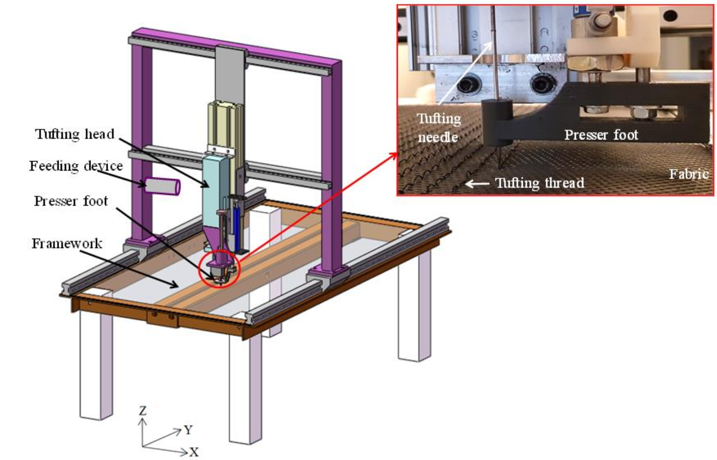 Fig. 1. Tufting device developed in GEMTEX laboratory.
2.2 Forming device
Fig. 2 shows the forming device used in the present study to characterize the textile reinforcements formability [8]. This device is equipped with a stamping punch which is actuated by a pneumatic jack. A blank-holder (square metal frame) provides a homogeneous distribution of the pressure applied by four pneumatic jacks. A transparent plexiglas die perforated in the middle and suitable with the shape of the punch. The preform is placed between the blank-holder and the die where the position of the fabric is controlled by a laser guide system. The transparency criteria of the two plexiglas plates (blank-holder/die) allows displaying the deformed reinforcement in-situ and in real time. The forming device is equipped with a load sensor (500 N ± 0.3%) that screen the evolution of the stamping force during the test, and a CCD camera is used to film the test in the top-view through the die.
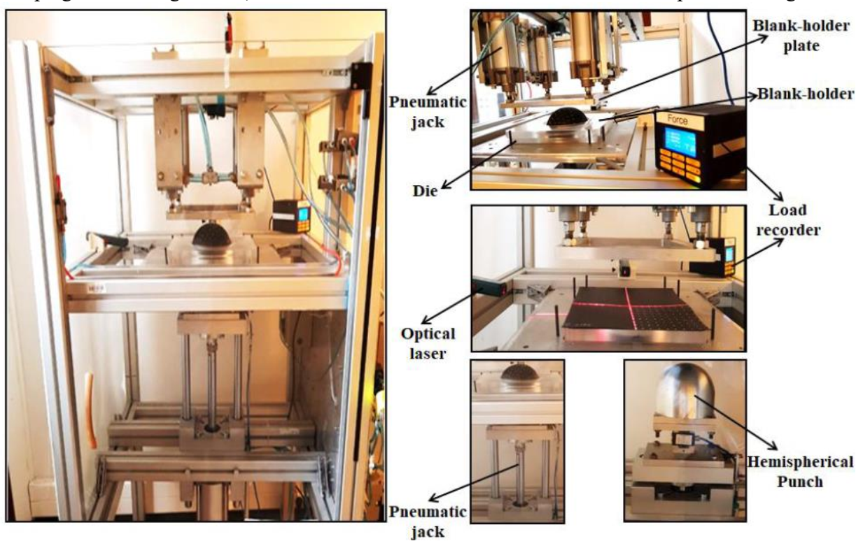 Fig. 2. Forming device and hemispherical punch.
Following the forming test, several specific properties can be evaluated: overall characteristics in terms of maximum material draw-in and forming force, as well as local properties such as the shear angle. Defects are also identified on the stamped preforms. The forming force is recorded by the load sensor connected to the machine. However, the maximum material draw-in is measured using the captures of the specimen before and after shaping. It is defined as the difference or the distance between the initial state and the deformed one. The maximum material draw-in was measured at the center points of four sides of the top layer oriented at 0°/90° for all tufted and un-tufted stamped preforms and evaluated as the average of the four measured values.
The preform's local properties are associated to the deformation modes, which are mainly related to shear strain for woven reinforcements. Experimental measurements of the shear angles are conducted through marking points. Before the stamping operation, a grid of white marking points is applied on each tufted or un tufted carbon preform, three points mark the angle between the warp and weft yarns formed the initial angle α=90°. After stamping, the white points move, and therefore, the angles between these points evolve. The angle between the warp and weft yarns is measured on the deformed preform using the recorded images and ImageJ software (Fig. 3).
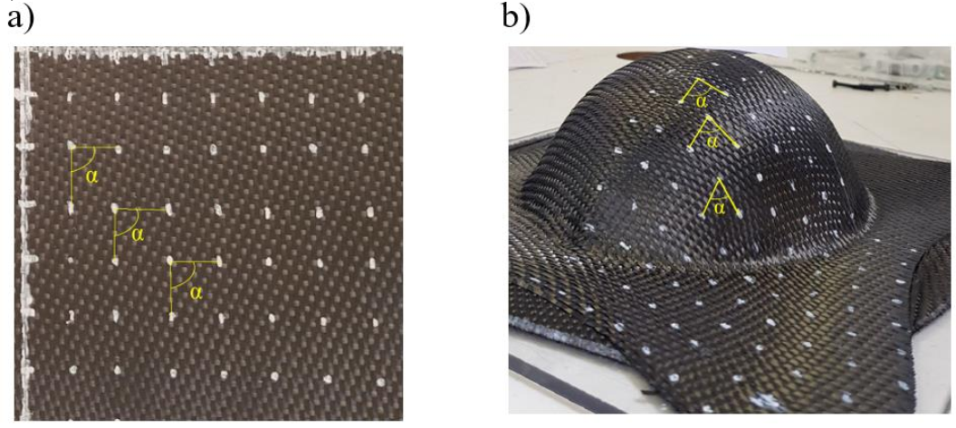 Fig. 3. (a) Initial state and (b) Deformed state.
2.3 Materials
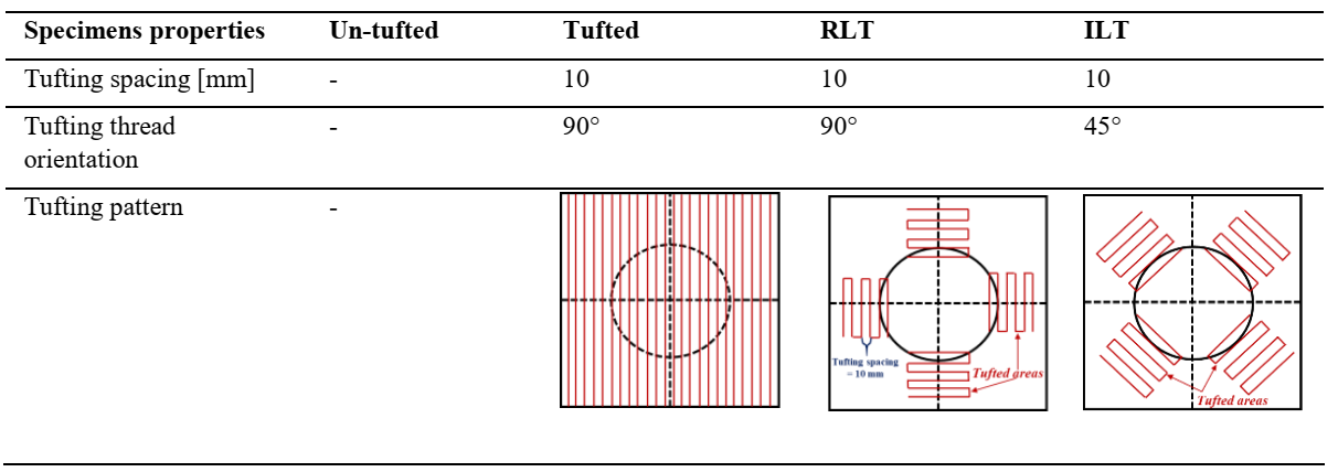
A five-harness-satin woven carbon fabric with an areal density of 290 ± 10 g/m² was used for this study. It is made of 6.5 warps/cm and 6.5 wefts/cm with a nominal thickness of 0.3 mm. Two stratification kinds of the woven fabrics are used: two and four layers oriented respectively at [0°/90°, -45°/+45°] and [0°/90°,-45°/+45°]2. The tested preforms' dimensions are 280 × 280 mm2. All samples were tufted with a cracked and twisted pure carbon tufting thread (134 Tex; 240 Tr/m) via a hollow needle of 2 mm diameter. In order to optimize the tufting process of two-layers dry carbon preforms, two localized configurations have been proposed: Right Localized Tufted (RLT) and Inclined Localized Tufted (ILT). The two localized tufting approaches consist of reinforcing only the most stressed area, the transitional zone of the punched preform, during stamping test. The main properties of
tested specimens are summarized in Table 1.
Table 1. Main properties of tested specimens.
3. Results and discussions
3.1 Forming force
The mean value of the forming force recorded on fully tufted and un-tufted preforms for both stratifications ([0°/90°, -45°/+45°]; [0°/90°,-45°/+45°]2) and for the two applied blank-holder pressures (0.05 MPa and 0.2 MPa) is shown in Fig. 4. The experiments were repeated three times at the two pressures and for all tested specimens where the error bars pointing out the standard deviations are shown on the graphs.
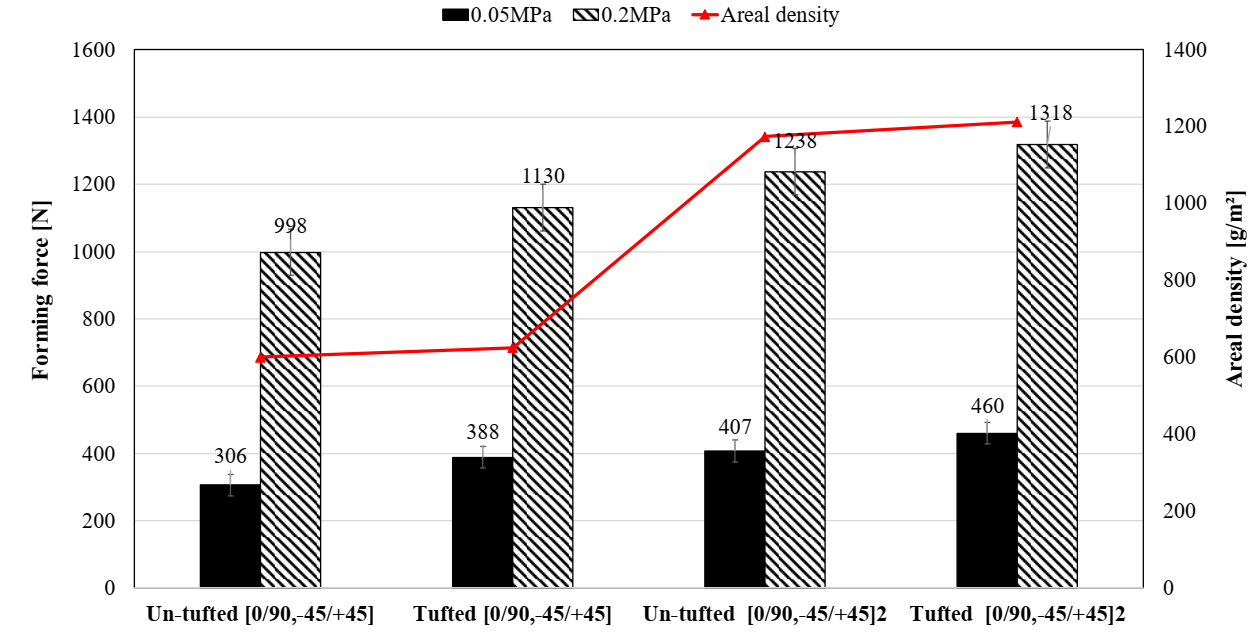 Fig. 4. Forming force of un-tufted and tufted preforms for both stratifications.
In the case of two reinforcing layers ([0°/90°, -45°/+45°]) and at a given pressure, the forming force varies proportionally with the increase of the areal density. The un-tufted preform has a punch force value less than the tufted one. The increase in blankholder pressure from 0.05 MPa to 0.2 MPa is marked by the rise in the forming force for all tested preforms. This is due to the increase of the friction forces in preventing ply sliding through the matrix and the blank-holder.
The same results were recorded for the preforms composed of four plies ([0°/90°,-45°/+45°]2) where the increase in blank-holder pressure leads to an increase in the forming force for all specimens.
However, for the localized tufting, the punch force of ILT is similar to the un-tufted while RLT is the highest one (Fig. 5). It is easier to stamp the ILT and un-tufted preforms than the RLT structure. The six rows of localized tufting are in normal incidence to the out-of-plane movement of the forming punch. The inclined rows, particularly at -45°/+45° in the case of ILT, promote more the movement of the fibrous reinforcement than those oriented at 0°/90° in the RLT configuration.
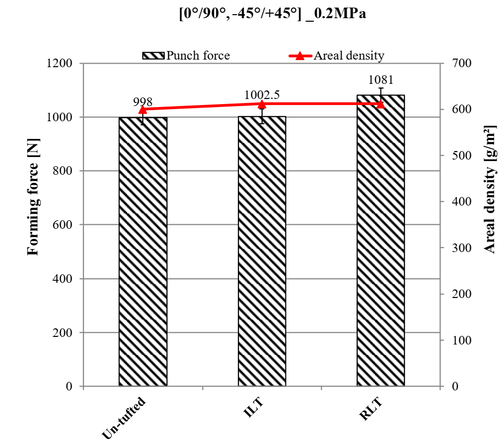 Fig. 5. Forming force for the [0°/90°, -45°/+45°] un-tufted and locally tufted preforms.
3.2 Maximum material draw-in
Fig. 6 a) highlights the maximum material draw-in of fully tufted and un-tufted carbon preforms for both stratifications. The highest material draw-in values are recorded for the un-tufted preform in comparison with the fully tufted structure. For the untufted preform, the layers have more degree of freedom and more shearing, which increases the material draw-in. The presence of tufting threads in the whole surface of the fabric prevents its material draw-in. The addition of the tufting thread leads to a reduction of the inter-layer slippage that impacts the yarn tension and, subsequently, a lower material draw-in.
The increase in pressure (from 0.05 to 0.2 MPa) reduces the average material draw-in for all tested specimens. This increase of pressure causes an increase of the inter-plies (ply/ply) and intra-ply (reinforcement roving/tufting thread) friction coefficient where the yarn tension is proportional to the blank-holder force. The augmentation of the friction forces leads to align the reinforcement rovings which become highly stretched.
Regarding the localized tufting (Fig. 6 b)), both optimized configurations reveal a similar material draw-in (27 mm) which is lower than that recorded on the un-tufted preform. The localized insertion of the reinforcement thread reduces the shrinkage of the dry preforms. The maximum material draw-in of two locally tufted preforms is lower than that of the totally tufted preform (Fig. 6). Thus, the two configurations proposed in localized tufting make it possible to reduce the material draw-in without increasing the punch force.
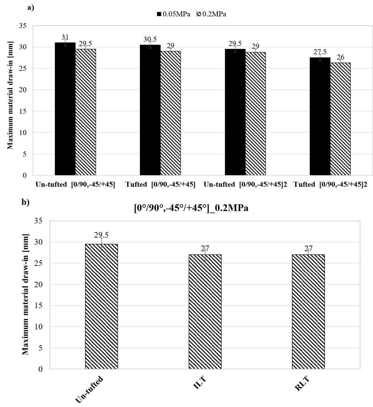 Fig. 6. Maximum material draw-in of: (a) [0°/90°, -45°/+45°] and [0°/90°, -45°/+45°]2 un-tufted and fully tufted preform and (b) [0°/90°, -45°/+45°] untufted and locally tufted preforms.
3.3 Shear angle and macroscopic observations
By raising the blank-holder pressure from 0.05 to 0.2 MPa, the shear angles increase, particularly in the transitional zone (Fig. 7). The tufted preform has a lower shear angle than the un-tufted fabric. This is due to the reinforcing thread which constrains the rotation between yarns during stamping. Similar shear angles are registered for both [0°/90°, -45°/+45°] and [0°/90°, -45°/+45°]2 stratifications for all tested specimens.
For locally tufted preforms (RLT and ILT), the ILT configuration exhibits the highest values of the shear angle just after the untufted preform. The tufting rows of the RLT prevent more the deformability of the fabric than the tufting rows applied at ±45° for the ILT. Thus, the ILT configuration is the most suitable for shear deformability. RLT and ILT preforms exhibit shear angles significantly greater than the totally tufted preform as shown in Fig. 7.
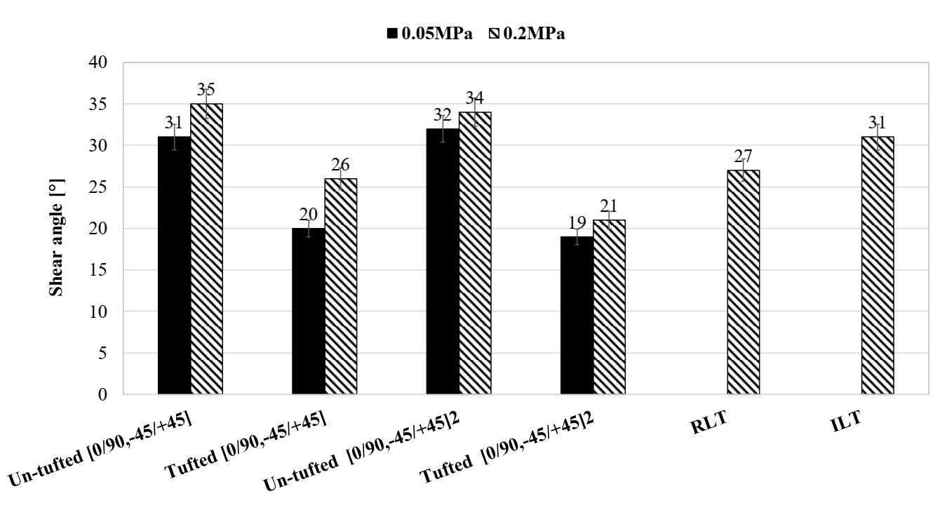 Fig. 7. Shear angles at the transitional zone of all tested preforms.
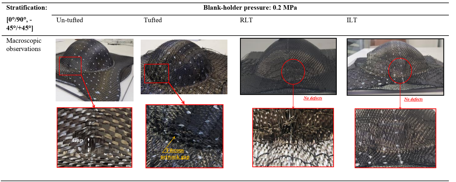
Regarding the macroscopic observations, more defects are recorded for all tested preforms by doubling the number of layers and the increase in the blank-holder pressure. These observations show that the stamping of the un-tufted preform does not generate noticeable defects compared to the tufted structures. A large gap is created between the yarns due to the increase of friction force where all tested preforms registered an intra-ply yarn sliding phenomenon on the transitional area.
A significant reduction in structural defects has been recorded for both RLT and ILT preforms where neither damage of the fibrous network nor removal swallowing of the loops were detected. No buckles and no inter-yarn slippage were recorded. Table 2 represents macroscopic observations of [0°/90°, -45°/+45°] stratification of tufted and un-tufted preforms tested at 0.2 Mpa.
Table 2. Macroscopic observations of tufted and un-tufted preforms.
4 Conclusions
Several tufted preforms with different stratifications ([0°/90°,-45°/+45°] and [0°/90°,-45°/+45°]2) were manufactured in order to study their deformability behaviour. The results show that the increase in the areal density and the blank-holder pressure lead to an increase of the punch force for all tested preforms. However, the material draw-in decreases with the rise of the pressure and the addition of the tufting points. The presence of the tufting thread reduces the inter-layer sliding as well as the material draw-in. Shear angles and macroscopic defects increase with the increase in blank-holder pressure for un-tufted and fully tufted preforms.
For localized tufting, it has been shown that the two innovative configurations present a similar punch force and a lower material draw-in than the un-tufted preform. The shear angles of the two localized tufting solutions are clearly significant compared to the fully tufted preform. The macroscopic observations reveal an absence of defects for RLT and ILT preforms.
In the future work, the studies about the in-plane mechanical properties, especially shearing behaviour, of tufted and un-tufted preforms will be highlighted.
Acknowledgments
The research presented in this paper was funded by the National Research Agency (ANR), France, in the scope of the project COMP3DRE "COMPosites 3D REnforcés".
