1 Introduction
Fiber reinforced composite materials are applied in the aerospace industry to enable lightweight, high performance aerostructures that help reduce fuel consumption and CO2 emissions. Press forming is a manufacturing technique for small to medium sized thermoplastic composite components in high volumes. In this process, a pre-consolidated blank is heated above the melting temperature of the polymer, quickly transferred to a press, shaped using a set of molds and solidified at the mold temperature whereafter the new part is released. This fast process can be applied to a wide range of materials and part geometries. Although, traditionally, woven fabric reinforced blanks of uniform thickness are employed, the aerospace is currently moving towards blanks of non-uniform thickness based on UD tape materials. Typical benefits of thermoplastic tape materials include good mechanical properties due to a high fiber volume fraction and opportunities in automated manufacturing of tailored components.
The challenge with press forming lies in the complex relations between part design, process design and final part quality, because a variety of defects can occur. Design tools in the form of finite element based composite forming simulations have been developed to address this challenge. However, increasingly complex parts in more demanding (structural) aerospace applications call for a more accurate prediction of wrinkling defects, particularly for UD materials.
The material description is one of the major aspects to consider for the overall accuracy of composite forming simulations. Deformation mechanisms are defined and used to ease the understanding, characterization and modelling of the overall deformation of a laminate [1]. Continuum based simulations typically model each ply in a laminate individually and distinguish the mechanisms of in-plane shear, bending, ply-ply friction and tool-ply friction. These individual mechanisms are characterized experimentally and described using models or look-up tables in the simulation. In-plane shear deformation is required to shape the material onto doubly curved surfaces without wrinkles, meaning that its characterization is essential for the prediction of wrinkling defects in complex parts. The current research addresses the accurate measurement and modelling of the intra-ply (in-plane) shear mechanism for thermoplastic UD tape materials.
A variety of characterization methods have been developed to measure intra-ply shear on thermoplastic UD material; an overview is provided by Haanappel and Akkerman [2]. However, no clear consensus has been achieved on a standardized test method to date. The picture frame and bias extension method are most widely used for fabric based composite materials [3], but also here no standardized test method has been realized despite initial benchmarking efforts [4]. Potter [5] has reported that the bias extension method can be applied for UD thermoset materials with cross-ply specimens to obtain deformations similar to a woven material. Similar results have been obtained by Larberg and Åkermo [6]. Such findings subsequently raise the question whether the same can be achieved on thermoplastic UD material. This paper describes the preliminary results of the bias extension method applied to thermoplastic UD material.
2 Bias extension implementation
2.1 Definitions and interpretations
The Bias Extension method features a rectangular specimen with fibers in 45° and -45º directions and a gauge length between the clamps of at least twice the width, see Fig. 1. The specimen is extended by a displacement of the upper clamp in length direction, in line with the so-called bias direction in case of a woven fabric. The deformations observed for woven fabrics in bias extension resemble those of a pin-jointed-net, which assumes inextensible fibers that cannot slip but only rotate at the cross-over points. As a result, the pin-jointed net predicts an area of uniform (trellis) shear deformation in the center (𝐴), triangle shaped areas originating at the clamps without shear deformation (𝐶) and four triangular areas with half the shear deformation of the center (𝐵) that connect the latter. The deformation in the center area is characterized by a shear angle, which is defined as the change in angle between the two fiber directions. The force 𝐹 required to apply the extension is a measure for the energy required to deform the material in in-plane shear.
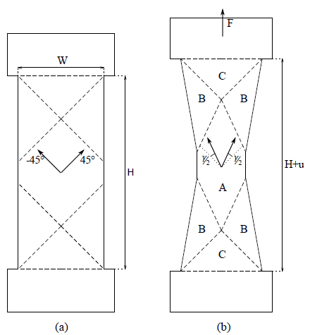 Fig. 1: Schematic drawing of the bias extension specimen incl. definitions. (a) before deformation. (b) theoretical deformation according to a pin-jointed-net. Arrows indicate local fiber direction.
According to the pin-jointed-net assumption, the shear angle 𝛾 and shear rate 𝛾̇ can be calculated according to:

respectively [3], using gauge length 𝐻, specimen width 𝑊, displacement 𝑢 and speed 𝑢̇.
2.2 Specimen preparation
Bias extension specimens were cut from an 8-ply press-consolidated laminate with a [45,-45]2s layup using a CNC milling machine. The laminate was press consolidated using Toray Cetex® TC1320 material, a unidirectional thermoplastic tape with AS4D carbon fibers (145gsm FAW) and a PEKK polymer matrix (RC 34%) [7]. The PEKK polymer has a glass transition temperature of 160 °C, a melting temperature of 337 °C and is typically processed in the range of 370-400 °C. The consolidated ply thickness is 0.14 mm, giving laminates with a nominal thickness of 1.12 mm. A dog-bone shaped specimen geometry, as shown in Fig. 2a-b, with wider areas for clamping was chosen over the general rectangular shape for better load introduction on the outer corners of the deformation field. A cross hatching pattern was applied in fiber direction for deformation measurement using a silver ink marker and a template. Additionally, four white dots are applied with heat resistant white paint. Specimens were dried for 3 hours at 250 °C and subsequently stored in a vacuum oven at 70 °C prior to testing in order to minimize the effects of deconsolidation [8] and thereby promoting specimen integrity during testing. Sanding paper was applied in between the specimen and the clamps to prevent sticking.

Fig. 2: (a) Specimen and pattern dimensions in millimeters incl. approximate thermocouple (TC) locations. (b) Examples specimens before and after deformation. (c) Bias extension clamp incl. insulation blocks
2.3 Experimental method
An Instron universal testing machine was prepared with a 1 kN load cell, bias extension clamping, a preheated climate chamber and a calibrated Instron advanced video extensometer (AVE2). For each test, a specimen and four insulation blocks, all at room temperature, are placed inside the preheated oven and secured in the clamps. The insulation blocks consist of 5mm thick fiber reinforced cement board with a clamping surface of 100x55mm, see Fig. 2c. A fixed heating time of 8 minutes is maintained to bring the central area up to the measurement temperature of 375 °C. The dwell time was kept brief to prevent the material between the clamps from melting. The temperature in the central area was verified by a thermocouple (TC1, see Fig. 2a) and a separate thermocouple in the clamped area (TC2) showed a temperature roughly 50 °C lower, by which it is estimated that a large part of the clamped area remained under the melting temperature. After the fixed heating time, a displacement of 36 mm was applied at a constant speed. Three different speeds, 100, 400 and 1000 mm/min, respectively, were used to observe the rate-dependency of the material. The deformation of the specimen was monitored in-situ using the video extensometer, which measures a strain in longitudinal 𝜀𝐿 and transverse direction 𝜀𝑇 by tracking the four white dots in the center of the specimen, see Fig. 2a-b. The silver-painted lines are not observed in the video due to automatic reflection correction. The shear angle, which is defined as the change in the angle between two fiber directions, is calculated using 𝛾 = (𝜀𝐿 − 𝜀𝑇 ) in radians. This relation is twice the radius of the circle of Mohr because of conversion to engineering (shear) strain.
2.4 Deformation analysis method
The deformed specimens were photographed after testing with a standard compact camera at 12x optical zoom to obtain a near-2D picture, as shown in Fig. 3. The deformation of the specimen was subsequently measured by comparing the location of the line intersections to their undeformed state.
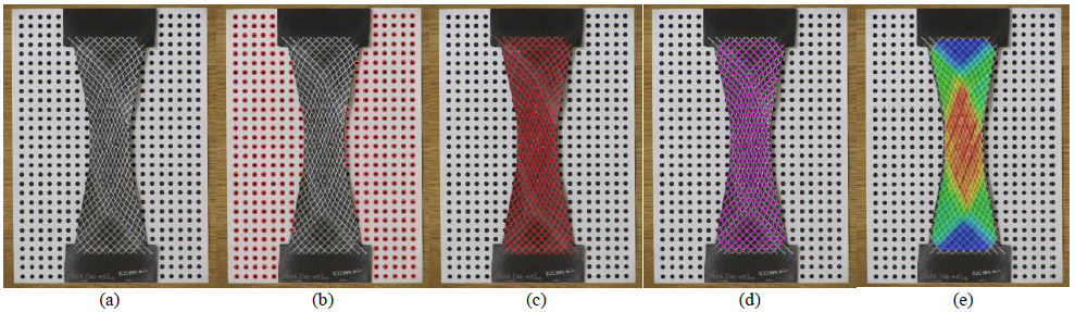
Fig. 3: Deformation analysis from a picture of the deformed specimen. (a) Original image. (b) Recognition of dotted pattern for scaling. (c) Traced lines on specimen. (d) Identified line intersections. (e) Partly transparent color plot of the measured shear angle.
First, a known pattern of dots in the background was detected using a standard functionality in Matlab (imfindcircles [9]) and used to determine the scale of the picture. The lines on the specimen were manually traced using Inkscape and the intersections of these lines were used to construct a triangular mesh on the deformed specimen. A similar mesh was constructed for the undeformed specimen by using the line intersections from the template used to apply the cross-hatching pattern. For each element in the mesh a deformation gradient was determined using:

with 𝑉1,𝑣1 a (column) vector between nodes 1 and 2 in the undeformed and deformed configurations respectively and similarly 𝑉2,𝑣2 is a vector between nodes 1 and 3. The deformation gradient can subsequently be used to transform the fiber directions:

with 𝐴 as unit column vector of the initial fiber direction and 𝑎 the resulting fiber direction in the deformed configuration. The shear angle in radians is calculated using:

where 𝑎,𝑏 are the fiber directions in the deformed configuration corresponding with the initial 45° and -45° fiber directions.
3 Results
Preliminary results are presented for the characterization response of the material along with multiple ways of data analysis.
3.1 Characterization
The preliminary results consist of three specimens tested at different test rates. The main result of the bias extension experiment is the force-shear angle diagram as shown in Fig. 4a. The force initially increases rapidly before leveling off and increasing again towards the end of the test. A higher rate results in more force required to deform the specimen, indicating viscous or rate-dependent material behavior.
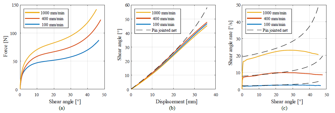
Fig. 4: (a) Preliminary Bias Extension measurement results. (b) Shear angle measured using a video extensometer (c) Shear rate.
The forces measured here are relatively high compared to the work of Wang et al [10] on a fabric carbon/PEEK material, where forces in the order of 1-10 N were found for a 70 x 210 x 0.31 mm3 specimen at 380 °C and 60 mm/min. Also, the initial steep increase in force is not commonly observed for fabric-based composites at processing conditions but both might be explained by a high viscosity value as a result of the high fiber volume fraction of the UD material.
The increase in force at larger deformation is common in many bias extension results for fabric-based composites and often explained as a locking angle of the fabric at higher shear angles. However, the convention of a locking angle is unlikely to exist for UD materials and a different underlying phenomenon is suspected. A possible explanation might be related to in-plane compression transverse to the fibers, which is inherently part of the trellis shear deformation observed in this experiment. The compression becomes more significant at higher shear angles and is presumably connected to a thickness increase to preserve volume. The additional flow required to accommodate the rearrangement of the microstructure could be related to the increase in force at large deformations. A planned constitutive modelling study based on these results will hopefully shed more insight into the observed material response.
3.2 Deformation, video extensometer
The shear deformation, measured with the video extensometer, as a function of the displacement is shown in Fig. 4b. It is observed that the measured shear angle is close to the theoretical deformation that is expected from a pin-jointed-net for the first 25 mm of displacement. Thereafter, the measured shear angle is less than the theoretical value, a result that is also commonly observed for fabric-based materials. The good correlation with a pin-jointed net for the first half of the measurement suggests that the cross-ply UD specimens have comparable deformation behavior to that of a fabric-based material. Furthermore, large deformation, with shear angles up to 45°, was introduced whilst maintaining a good specimen integrity.
The shear rate shown in Fig. 4c provides a different view of the deformation throughout the test by examining the time-derivative. The rate in the experiments is nonetheless consistent with the pin-jointed-net theory up to 25° shear angle. For larger shear angles the rate shows a slight decrease instead of the steep increase expected from a pin-jointed-net.
3.3 Deformation, grid of lines
The silver lines applied to the specimen prior to testing, see Fig. 2b, can be used to gain additional insight into the local deformation on the outer ply. The lines are initially aligned with the two fiber directions of the cross-ply layup. Fig. 5 shows close ups of two grid cells, where the rhombus shape of the cell clearly illustrates the shear deformation, but shear banding has also occurred parallel to the fiber direction. The shear banding is most pronounced in the center, the bottom left and the top right areas of the specimen, where the fibers on the outer ply are free on either end. Very little shear banding is found in the top left and bottom right, where one end of the fiber is supported in the clamped area. The shear banding phenomenon suggests the existence of a yield point combined with softening on the meso scale, however, this is not directly observed from the macroscopic response of the material. Note that only the deformation of the outer ply can be observed, and that the deformation of internal plies might be different because of support on either side (no free surface).

Fig. 5: Close ups of a bias extension specimen after testing (100mm/min)
The deformation analysis method described in section 2.4 was used to measure the average local shear deformation in each grid-cell, the results are shown in Fig. 6. The areas with constant shear angles according to the pin-jointed-net can be readily recognized from the deformation analysis results. However, it is also observed that the deformation distribution in the respective areas is non-uniform for all three specimens, mainly in the center area. The non-uniformity seems inconsistent between specimens, with some having lines due to shear banding and others having more smoothed differences over a larger area. The observed non-uniform deformations might be related to inexact clamping and/or material inhomogeneity.

Fig. 6: Shear deformation fields for three specimens a) 100mm/min b) 400mm/min c) 1000mm/min
The average shear angle in the center as measured by the video extensometer during the experiment can also be determined from the image analysis by calculating the longitudinal and transverse strain between the dot locations. The shear angle values obtained from the video extensometer at the end of the experiment correspond to within 1° with the value obtained through image analysis, indicating that no significant (macroscopic) deformation has taken place between the end of the experiment and the photograph of the specimen.
4 Conclusion
Preliminary results were presented for bias extension experiments on cross ply laminates from thermoplastic unidirectional carbon fiber reinforced tape at processing conditions. The deformations observed are similar to those typically observed on woven fabrics, where in-situ deformation measurements with a video extensometer showed the deformation to be consistent with a pin-jointed-net up to a shear angle of 25°. The material response shows similarities with those observed on woven specimens, but a high intra-ply viscosity is suspected due to the steep increase towards relatively large force that is observed. A constitutive modelling study should provide more insight into the measured material behavior. Additional deformation analysis, using a grid of lines, shows regions with shear banding on the outer ply as well as a non-uniform shear distribution on the deformed specimen. This work may contribute to improved understanding of intra-ply shear of thermoplastic UD materials and will proceed with modelling of the observed responses for forming simulations, thereby aiding in the accurate prediction of processing defects for press forming of lightweight, high performance thermoplastic composite aerospace parts.
Acknowledgements
This work is part of the research program “MaterialenNL” with project number 17880, which is (partly) financed by the Dutch Research Council (NWO). The authors also gratefully acknowledge the financial and technical support from the industrial and academic members of the ThermoPlastic composites Research Center (TPRC), as well as the support funding from the Province of Overijssel for improving the regional knowledge position within the Technology Base Twente initiative.
