1 Introduction
Stamping associated with over-molding process combines several manufacturing techniques to create parts with integrated functions. This approach is advantageous in aeronautics and automotive applications not only to reduce production time, by avoiding secondary operations, but also to fabricate hybrid lightweight structures combining metals, composites, and polymers according to their final purpose. This process could be divided in 5 main stages (Fig. 1). First, high-performance thermoplastic composites blankets and metal inserts are preheated with radiation panels. They are then transferred into the mold cavity to be stamped. This press-forming stage is then followed by the over-molding with a thermoplastic resin. The part is cooled down and removed from the mold. Finally, the mold temperature is raised to attain press-forming conditions and to let another cycle start.
The processing of High-performance thermoplastic such as PEEK or PEKK associated with carbon fibers is still subject of research. These materials have high processing temperatures compared with other standard polymers [3], creating non-negligible temperature differences throughout the entire manufacturing process.
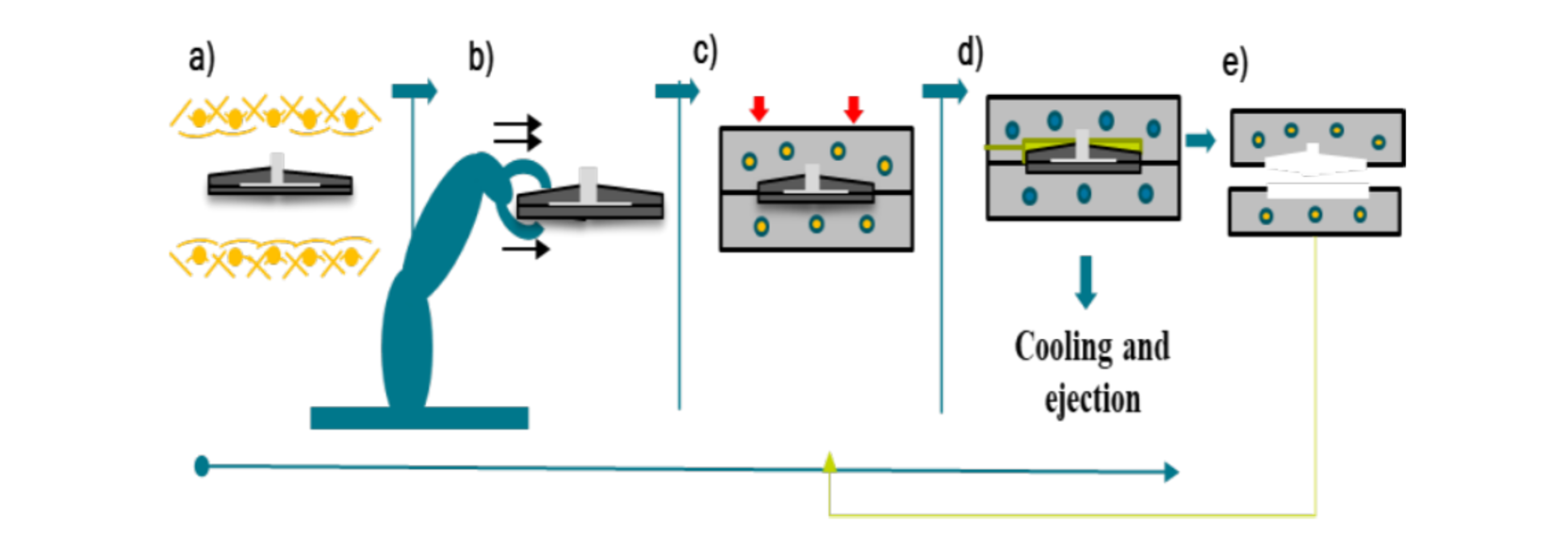
Fig. 1. Hybrid manufacturing process example. (a) Preheating (b) Transfer (c) Stamping (d) Over-molding (e) Mold temperature rise.
Temperature variations could generate thermal expansion and contraction at different locations within the part, leading to thermal residual stresses and, as a consequence, several defects, such as shrinkage, fiber waviness, transverse cracking, delamination, and warpage [4]. Different studies have shown that the magnitude of residual stresses depends on the processing conditions, as for instance, thermal gradients during the cooling stage [5]. That is the case of an early investigation made by Manson et al. [6] about the process-induced effects during the preforming of Continuous Fiber thermoplastics composites. They showed that higher cooling rates cause higher voids contents and fiber buckling, damaging the composite material. They also observed that high cooling rates reduce the crystallinity rate of the polymer, reducing their mechanical properties.
Certainly, process conditions affect quality, but it has been proved that they can also have a direct impact on productivity. In the forming stage, high mold temperatures increase cooling time [7] and hence time cycle [8]. Longer production times generate higher costs [9] and energy consumption. Looking at a different manufacturing stage, such as the pre-heating of materials, optimum processing conditions are important as well, since they can also help to reduce cycle time and material damage [10]. Based on this, it becomes evident, that control of thermal related parameters is an essential element at each manufacturing stage of the process to guarantee quality and productivity. Therefore, to avoid the aforementioned problems, it becomes mandatory to have a thermal design methodology that takes into account the main stages of a manufacturing process, but also other challenging aspects like geometry complexity or interaction between different assembly materials at each manufacturing stage.
In this field, several works have been oriented on the optimization of the thermal profile of the part during the manufacturing process. These studies propose a series of optimization algorithms based on deterministic or stochastic methods or a combination of both, as well as different methodologies based on the conventional or conformal approach. This last approach proposed by Xu [1], has been proved to be very efficient when compared with the conventional approach, to optimize temperature distribution within the part [2, 9, 11]. Inspired by this method Agazzi[2] proposes the creation of a contour (dilated zone) reproducing the shape of the part, as close as possible to the mold’s surface [1] reducing computational time since a more reduced geometry is analyzed. The methodology is based on a first-order optimization algorithm throughout an inverse problem. The strategy is applied only to the cooling stage and it was proven to be very efficient in reducing the temperature gradient on the surface while arriving to an established temperature. Hoppmann [13] extended the methodology proposed by Agazzi [2], taking into account a holding time and a different objective function, proving the versatility of the application. On the consulted researches only one kind of manufacturing technique is considered and mostly applied to mono-materials.
This study proposes a design methodology that takes into account all the stages of a thermo-stamping of high-performance thermoplastic composites with a metal insert followed by an over- molding. To do this, an inverse optimization algorithm is proposed, with the aim of obtaining the time and space heat flux distribution that minimizes a target condition, based on quality and productivity criteria.
1 Thermal design methodology
1.1 Model geometry
The selected manufacturing process includes 2 impregnated High-Performance thermoplastic sheets made from carbon or glass fibers, also known as Organosheets [16], one metal insert in the center of the part and an over-molding resin at the top surface. The geometry is going to be studied as a 2D axisymmetric problem as shown in Fig. 2. The analyzed geometry is built in Comsol Multiphysics® and has 4 domains corresponding to a metal insert (Ω1), 2 HP-TPC organosheets (Ω2), a dilated zone (Ω3) , and th over-molded region (Ω4). The distance of the dilated zone can be variable. Nevertheless, care must be taken to avoid thermal stresses in the mold part. For this reason, a minimal distance should be established. Here the dilated zone, as a replacement for the mold part, is created with a distance of 15 mm as proposed by Agazzi [2] and Hopmaan [13].
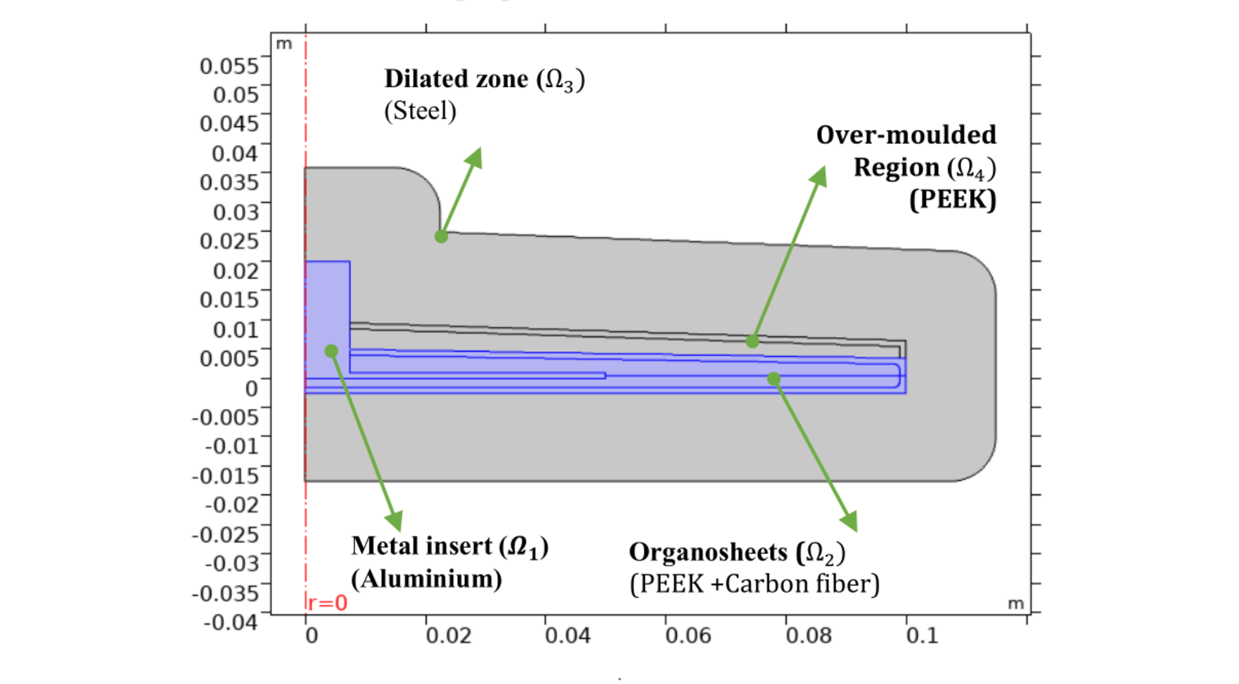
Fig. 2. Study case. Multi-material approach: geometry composed by for domains.
This study proposes a design methodology that takes into account all the stages of a thermo-stamping of high-performance thermoplastic composites with a metal insert followed by an over- molding. To do this, an inverse optimization algorithm is proposed, with the aim of obtaining the time and space heat flux distribution that minimizes a target condition, based on quality and productivity criteria.
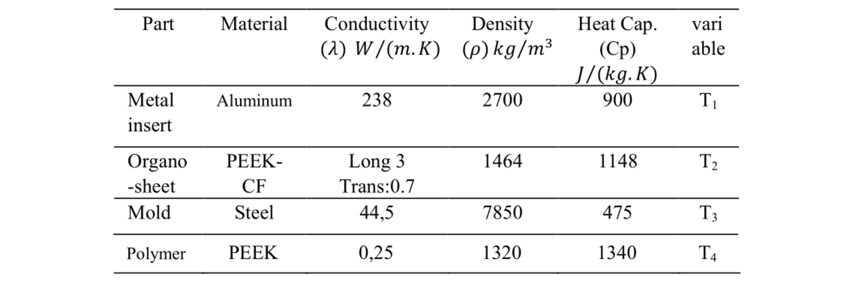
Table 1. Material Properties.
1.2 Process conditions
Process design values were estimated according to process requirements and hypotheses made for each stage:
-
Preheating stage: convection and radiation exchanges between the composite and surroundings are going to be taken into account in a global heat transfer coefficient in order to linearize the problem.
-
Transfer stage: all the parameters are considered known, as a result, the global heat transfer coefficient is obtained for a fixed transfer time. This coefficient depends on the speed and trajectory of the part.
-
Stamping stage: the initial mold temperature is considered homogenous for the first optimization cycle as per [2, 13]. Its value is calculated according to the temperature required within the part and the supposed Thermal Contact Resistance (TCR).
-
Over-molding: An injection temperature for the melted polymer is fixed to 360 °C. No phase change is assumed. Over-molding time comprises packing phase and cooling. It is calculated based on the time constant at the over- molded region and thermal diffusion time on the dilated zone.
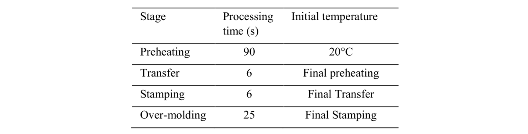
Table 2. Process conditions.
1.3 Computational formulation
The heat transfer problem is solved using the Finite Element Method, considering a transient analysis in each domain at different stages. Assuming constants properties for all materials and no power generation, the heat transfer equation is defined by:

Where i, correspond to each domain and Ti(r,z,t) the corresponding temperature field. Boundary conditions of the third kind are imposed on all the internal and external boundaries. Thermal contact resistances are assumed to be constant for all the contact domains. Nevertheless, this value should be properly adapted.
1.3.1 Optimization strategy
The process is divided into three optimization blocks: the first one includes, the preheating and transfer stages, where no dilated zone is included. The aim is to find the heat flux that must be imposed during the preheating stage, on the external surface of the part, to reach a target condition in the part, defined by an objective function at the end of the transfer stage. This means that both stages are considered coupled, and that the searched parameters at the preheating stage are going to depend on the heat transfer evolution at the transfer stage. A second optimization block is for the over-molded stage. The purpose is to find the heat flux distribution as a time and space function to be imposed at the external boundary of the dilated zone during this step of the process. The third block includes the mold rising temperature stage and stamping stage. The aim is to obtain the required heat flux distribution in this stage. Once the first optimization cycle is obtained, subsequent cycles are performed until a stationary condition is reached. The objective function is the same for all the optimization blocks.
1.3.2 Design variable
Looking for a proper heat flux distribution as a function of time and space, to avoid thermal related defects at each manufacturing stage, temperature distribution T∞n(r,z,t) at the external boundaries, is selected as design variables in each optimization block. This temperature is used later to obtain the heat flux distribution.
1.3.3 Objective function
The objective function is the mathematical expression of the searched condition at a specific time in the process. Its formulation depends on the design variables and the problem requirements. To obtain proper quality and productivity different authors have proposed some criteria based on time process and temperature gradient minimization [2, 13, 14, 15]. In this study, the objective function is composed of two terms. They correspond to a temperature homogeneity and a target value, as proposed by Agazzi [2]. These terms are used at each optimized stage and expressed as follow:


Where n corresponds to the optimization blocks going from 1 to 3; qn the searched heat flux distribution per block; Γ is an internal boundary (erode segment) located to 1mm from de external surface of the studied part; Γ* is the external boundary of the part; tf,n is the final time of the optimization block. The total function is then the summation of the equations 2 and 3.
Target temperatures per optimization block are defined according to the material process requirements. For the first block, the target temperature depends on the processing temperature window of the material, placed between 320 °C and 360 °C [12] which means that is higher than the melting point in order to be stamped but paying attention to avoid burning the material. Thus, a target temperature of 347 °C has been fixed. For the over-molded stage which includes cooling, the target temperature depends on the solidification temperature of the material. For this reason, it has been set to 230 °C. For the third block, the target temperature is intended to facilitate adhesion between the composite and the injected polymer. Since higher temperatures help to the healing phenomenon between materials a target temperature at the end of the stamping stage has been set at 340 °C.
1.3.4 Constraints
The optimization problem is subjected to upper and lower temperature limits at each optimization block an expressed as follow:

Lower level is set to 20 °C and upper level to 1700 °C.
1.3.5 Sensitivity analysis
Since sensitivity problem allows to obtain the response of the observed variable T2,n(qn) in the objective function, with respect to the design variable T∞n(r,z,t), it allows the validation of the dilated thickness, as well as, the location of the eroded segments with respect to the design variables. For each optimization block, a perturbation δT of a unit is imposed on the design variable. The sensitivity is then obtained at the corresponding eroded zone. The problem is solved using Eq.5 throughout the finite element method, using the same discretization as the direct problem.

1.3.6 Optimization Algorithm
The optimization is performed via an inverse technique that employs a conjugate gradient algorithm (Fig. 3). This is a first- order optimization algorithm that uses the gradient as a search direction to converge towards a local minimum. The gradient expression is obtained throughout the adjoint state, this is very useful when it doesn’t exist an explicit relationship between the design variable, T∞n(r,z,t) and the control variable, T2,n(qn), in the objective function.

Fig. 3. Conjugate gradient algorithm applied to each optimization block. Adapted from [2].
To obtain the adjoint state equations a Lagrangian is expressed as follow:
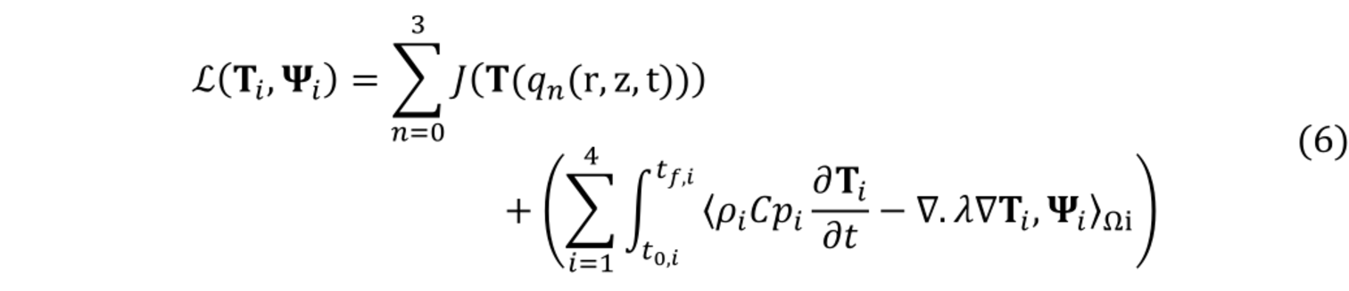
Where Ψ is the adjoint variable; t0,i and tf,i are the initial and final times in which each domain is activated. The set of the adjoint equations, as well as the gradient expression, are then obtained considering a stationary condition of the Lagrangian. The final expression of the gradient is as follow:

Where Γext,n is the external boundary, at the corresponding optimization block, where the heat flux is searched; hext is the heat transfer coefficient on Γext,n and; t is the time of the process in which the heat flux is going to be found. The adjoint variables at each domain are obtained solving backwards in time the set of equations, while the deepest descent is calculated using equation 8 for each iteration k.
Where δT2 is the solution of the sensitivity problem on the composite part (Ω2).
2 Results and discussion
2.1 Sensitivity analysis
The sensitivity analysis helps in the determination of the deepest descent. It is also useful to verify that the length of the dilated zone is selected correctly. A greater thickness of the dilated area would give lower sensitivity values making impossible to use the current methodology.
Furthermore, process time also plays an important role. Usually, the higher the time, the more the sensitivity increases. However in the 1 st optimization block, including preheating and transfer stage, the design variable T∞n(r,z,t) is on a different time window of that of the observed temperature T2,n(qn) at the eroded segment. That means that for higher transfer’s times, the observed temperature at the end time is going to be farther in time from the design variable, decreasing the sensitivity with respect the design variable.
With reduced sensitivity values, the inverse method cannot be carried out. That is the case of the stamping stage where the sensitivity has low values due to the short time process Fig. 4. In this stage, even when sensitivity increases with time, there is not enough time to properly use the methodology. This also means, that the temperature profile within the part at the end of the stamping stage depends more on the initial mold temperature profile than the heat flux imposed on the dilated zone over this time.
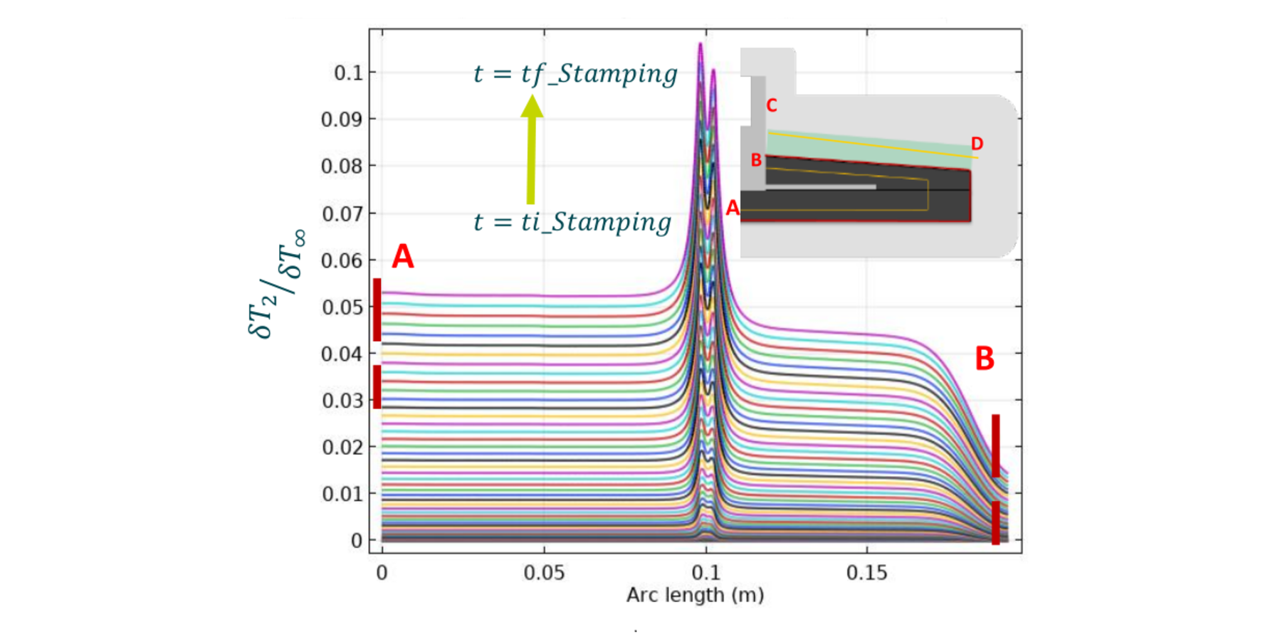
Fig. 4. Sensitivity results for the stamping stage, on the erode line (AB segment) from ti: initial time to tf final time.
Knowing the sensitivity, linked to the time process, helps to establish a good time discretization step for the gradient calculation. In this application, the last discretization step must be larger than the time required to attain a sensibility value greater than 0.05. The smaller the time discretization is, in the gradient equation, the less sensitivity we have. Therefore, the results are either more dependent on the initial guess during optimization, or impossible to obtain.
2.2 Optimization block 1: Preheating and transfer
On the first optimization block, the aim is to find the heat flux distribution over the external boundaries that minimizes the objective function, defined by a combination of target temperature at the eroded zone and homogeneity on the external surface. The design variable is considered constant in time as done by Hopmann [13] and Agazzi [2]. However, in this case the design variable is in a different time window of that of the objective function. The results are compared with a non-optimized case, resulting of imposing a constant design variable over time and space. In Fig. 5 it can be seen an improvement of the profile distributions within the part.
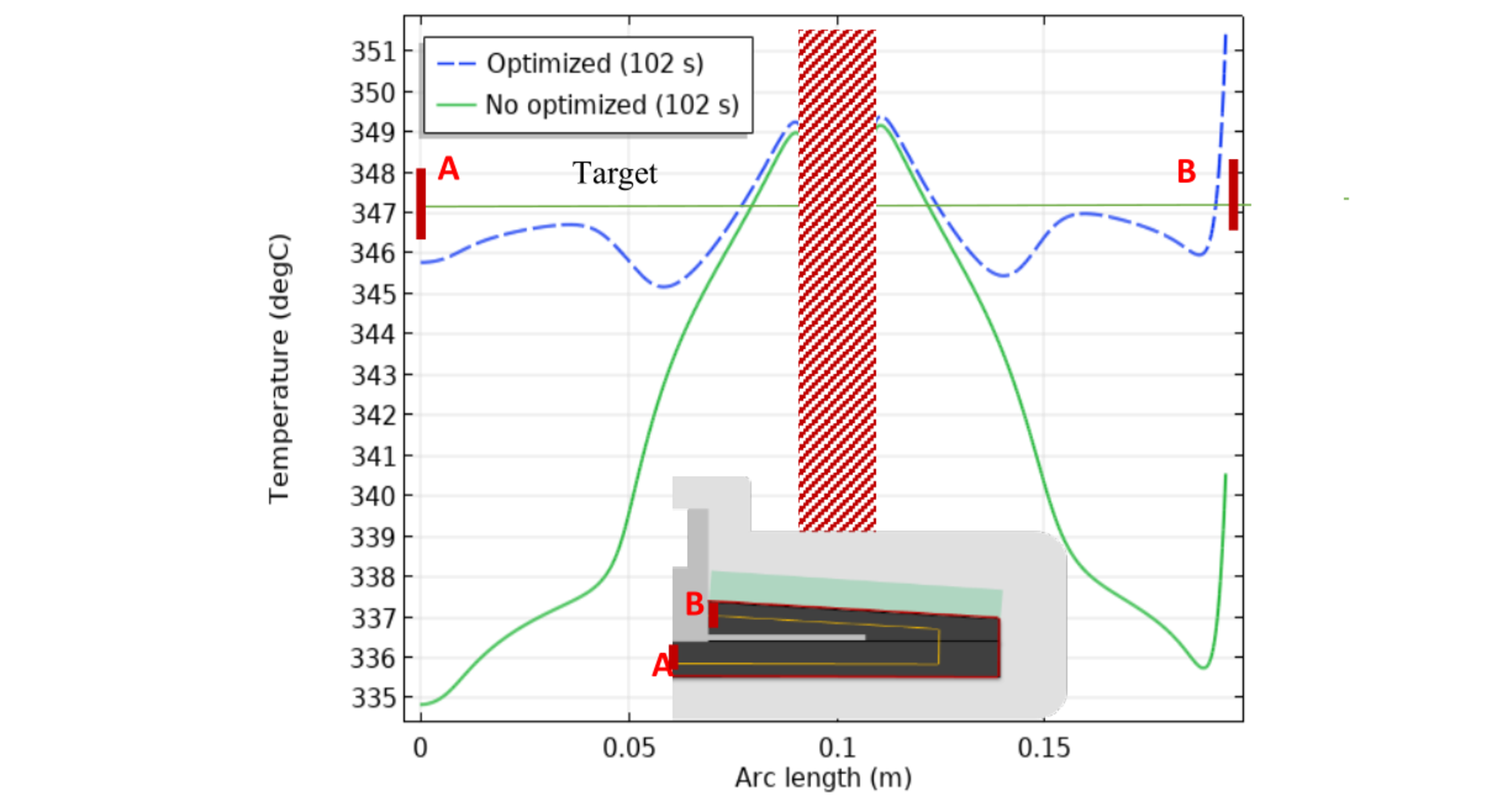
Fig. 5. Comparison of temperature profiles on the AB segment at the final time of the transfer stage.
In this case, the metal insert and the composite organosheets were heated at the same time. The optimal condition at the end of the transfer stage is used as initial condition for the stamping stage.
2.3 Optimization block 2: Over-molding
The optimized temperature distribution at the end of the transfer stage, and a homogenous mold temperature, are taken as initials conditions for the stamping stage. At this moment any optimization is made on this part of the process. Nevertheless, we used the non-optimized final temperature profile of the stamping stage as initial condition for the 2nd optimization block (Over-molding) . In here, we look for a temperature distribution as a time space function that minimizes the objective function.
After optimization, there is a good agreement between the target temperature and the optimized profile. Average temperature being 223.2 °C before optimization and 229.4 °C after optimization, on the bottom erode line of the part, resulting in temperature difference of less than 1 °C, with respect the target temperature at the end time.
To obtain this improvement, it can be seen in Fig. 6, that temperature distribution T∞2(r,z,t), on the external boundary Γext of the dilated zone, increases with time, which can be contradictory. This behavior is due to a small time step discretization in the gradient calculation, and the initial guess value in the optimization loop. Because, with this conditions, the problem is constraint to have a final profile near of the initial guess (210 °C) at the external boundary of the mold. In this way, it cools down in the first steps and then increase the temperature slowly. The optimized heat flux distribution is displayed in Fig. 7.
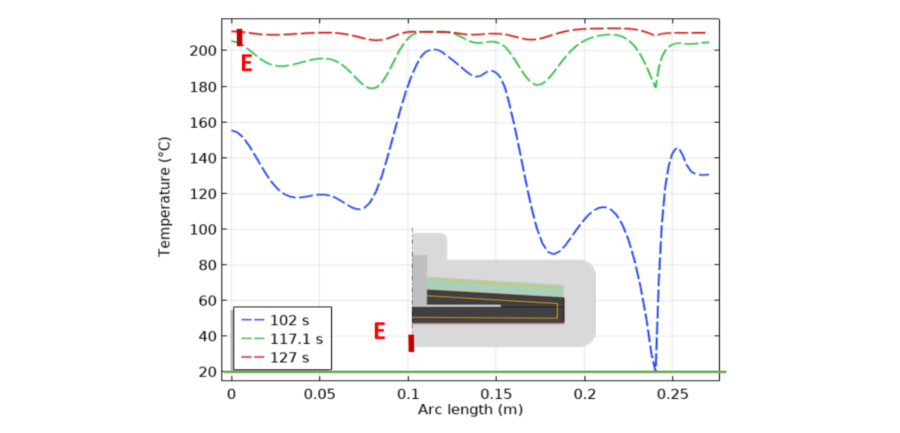
Fig. 6. Design variable distribution in time and space.
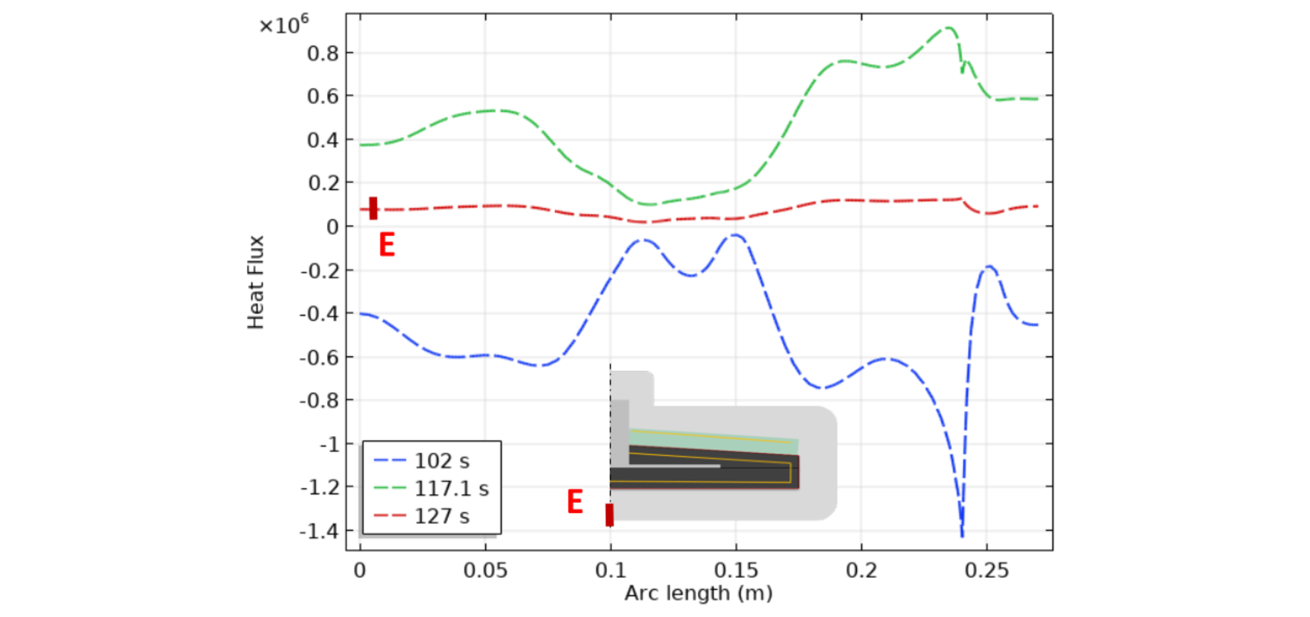
Fig. 7. Optimized heat flux distribution in time and space for the 2nd optimization block (over-molding stage). Heat flux W/m².
2.4 Optimization block 3: Stamping
Since, it is not possible to perform the optimization only in the stamping stage due of a lack of sensitivity. In this optimization block, we take into account the mold rise temperature stage and the stamping stage.
The objective is to find the heat flux distribution, over the temperature rise and stamping combined, that minimizes the objective function. After optimization, noticeable improvement of the temperature profile is obtained. As shown in Fig. 8, a maximum of 5 °C deviation with respect the target is obtained in the optimized case. Fig. 9 shows the profile distribution as space function of the heat flux after optimization.
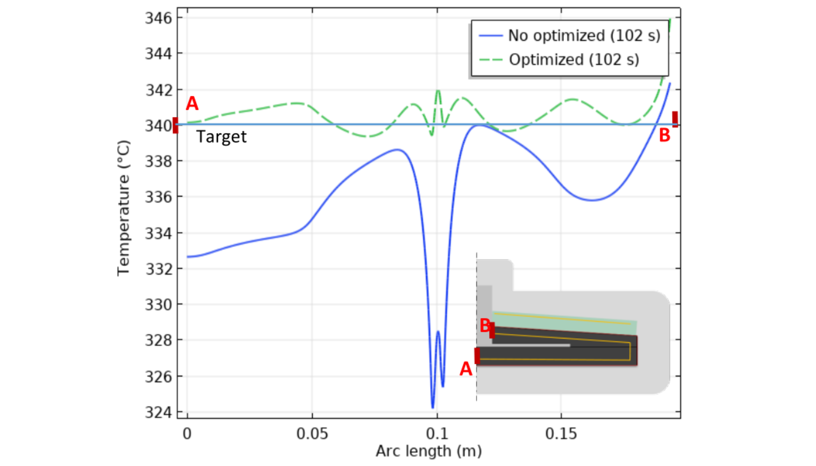
Fig. 8. Comparison of temperature profiles over the segment AB.
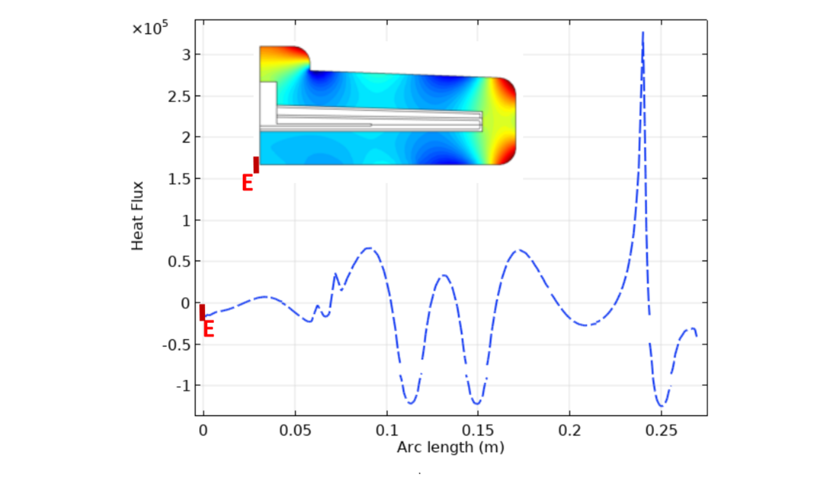
Fig. 9. Optimized heat flux distribution in space on Γext.
2.5 Cycle evolution
We run the optimization block 2 and 3 until a stationary condition is reached. The average temperature is about 340.6 °C, so a deviation of less than 1 °C respect to the target is reached. Having the same initial guess and time discretization for the gradient as for the first cycle, the heat flux reacts in the same way, going from lower to upper temperatures. Nevertheless, it have to cold even more than the first cycle, as suggest the profile at 102 s in Fig. 10. This is because the initial temperature profile in the dilated area is higher than the homogenous profile from the first cycle.
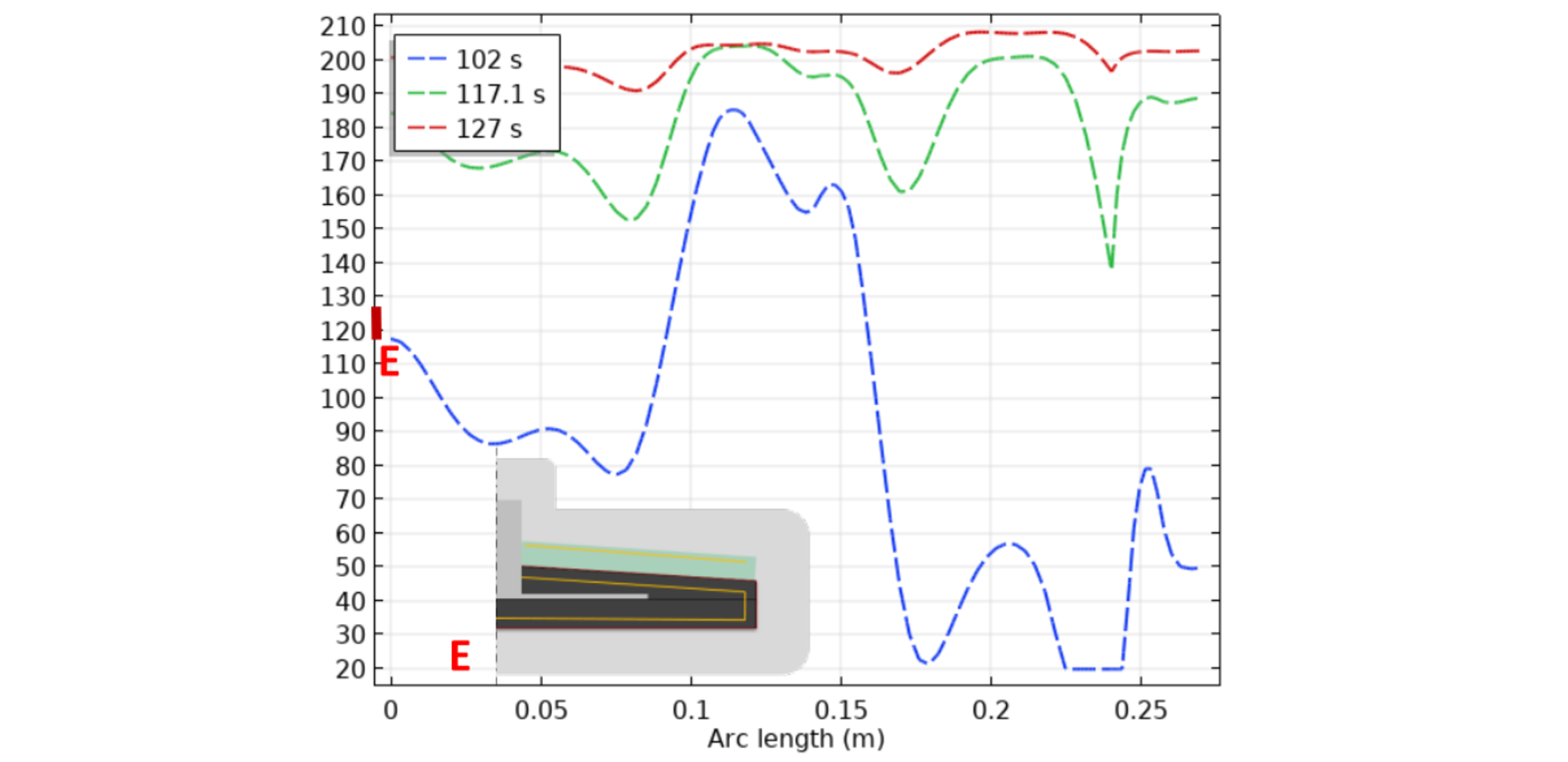
Fig. 10 Results block2-2nd Cycle: Design variable distribution in time and space. Temperature (°C) Vs. Arc length(m).
3 Conclusions
An optimization algorithm that combines different stages of a manufacturing process is presented. The methodology includes 3 optimization blocks. The 2nd and 3th blocks use the conformal approach, due to the proven efficiency [2,12]. This methodology is based on an inverse method to solve the problem subjected to constraints. The numerical problem is solved using the finite element method. A heat flux distribution varying space and time is found. Temperature profile profiles present a good improvement after optimization, with temperature variation smaller than 5 °C. Initial guess and time discretization of the gradient plays a key role during the optimization. Due to de dependence of the results on the initial guess of the design variable in the optimization loop, a PSO algorithm is ongoing to find the best initial value, but also another term in the optimization function is going to be suggested to minimize the total energy consumption in the entire process. Experimental validation for a part of the process is going to be considered as well.
4 Acknowledgements
The authors would like to acknowledge the funders of the PERFORM project managed by the IRT Jules Verne (French Institute for Research and Technologies for composite, Metallic and Hybrid Structures) as well as their associated partners of the PERFORM project: Airbus, Daher, Europe Technologies, Faurecia, Loiretech, Naval Group, SAFRAN and Stelia Aerospace.
