1 Introduction
The additive manufacturing (AM) technologies include all processes that realize components by adding material layer by layer. These technologies can be classified into seven categories: vat photo polymerization, material extrusion, material jetting, binder jetting, powder bed fusion, direct energy deposition, sheet lamination. AM differs from the traditional processes thanks to four main capabilities: shape complexity, material complexity, hierarchical complexity, functional complexity. These abilities can be applied to different areas, according to the technology employed. The redesign of the cooling system of the moulds, for example, is getting great interest because better cooling performances allow to improve the quality of the parts and reduce the production cycle time. However, the conventional manufacturing processes limit the optimization of the cooling system, that usually consists of simple straight channels unsuitable for moulds with complex shape. Thanks to the evolution of the AM technologies, it is possible to realize complex channels conformal to the mould geometry (i.e., conformal cooling), reaching high cooling performance. In the literature, research about this technique focused the attention on the optimization of the thermoforming process and injection moulding. A study made by Saifullah and Masood [1] reveals that conformal cooling channels can greatly improve the injection moulding process, reducing the mould temperature of 9 °C and the cycle time of 20 %. Another study made by Brooks and Bridgen [2] analysed the use of lattice structures together with conformal cooling; the lattice structures work as supports for the cooling channels. By this way, the motion of the refrigerant fluid becomes turbulent, optimizing the cooling process (cooling time reduced of 26 %). Other researches provide some guidelines for the design of the cooling channels. In the study of Voynova [3] for example, it has been suggested to place the channels near the hottest zones, choose their optimum section, realize an optimum distribution of the channels around the shape of the mould and not compromise the stiffness and the resistance of the mould. Yung Wa et al. [4], proposed an automatic method for the design of the cooling channels. Luca Giorleo et al. [5] optimized the cooling channel of a thermoforming mould to improve the production cycle performance.
The state of the art highlights that the increase of geometrical complexity results also in a more complex fluid dynamics of the refrigerant fluid. To better design the cooling channels performance a computational fluid dynamics (CFD) is the perfect approach to simulate the fluid dynamics involved. Thus in this work, to enlarge the knowledge about this methodology, a validation procedure for conformal cooling simulation is provided. Thanks to a CAD software, the mould cooling channels were engineered, then tested with a CFD software and produced to perform experimental tests. Fluids temperature, volume flow rates and heat transfer performance were measured. A feedback loop was considered to link measurements and future channels redesign.
2 Materials and Methods
The present work compared CFD simulations with experimental data gathered in a system designed to mimic the cooling process of a mould. The final goal is to realize and validate a simulation tool applicable to design and optimize conformal cooling circuits for injection molding.
As a first step, an experimental test rig was realized to measure heat transfer in a 3D printed polymeric sample representing a mould. To perform heat transfer measurement the mould was converted in a sort of heat exchanger. It was fed with two water streams: a cold flow that passes throughout the mould cooling channels and a hot flow that enters the injection pool which, instead of being a dead-end space, was modified adding an outlet duct. In the following sections, the mould, the test rig and the simulation approach used are described in details.
2.1 Prototype Design
The geometry of the specimen used in this work is shown in Fig. 1 and 2. The internal cavity has a diameter of 85 mm (Fig. 1b) and a height of 10 mm and it can be filled through the circular channel highlighted by the red arrows of Fig. 1a-1b.
Fig. 1. Specimen geometry. 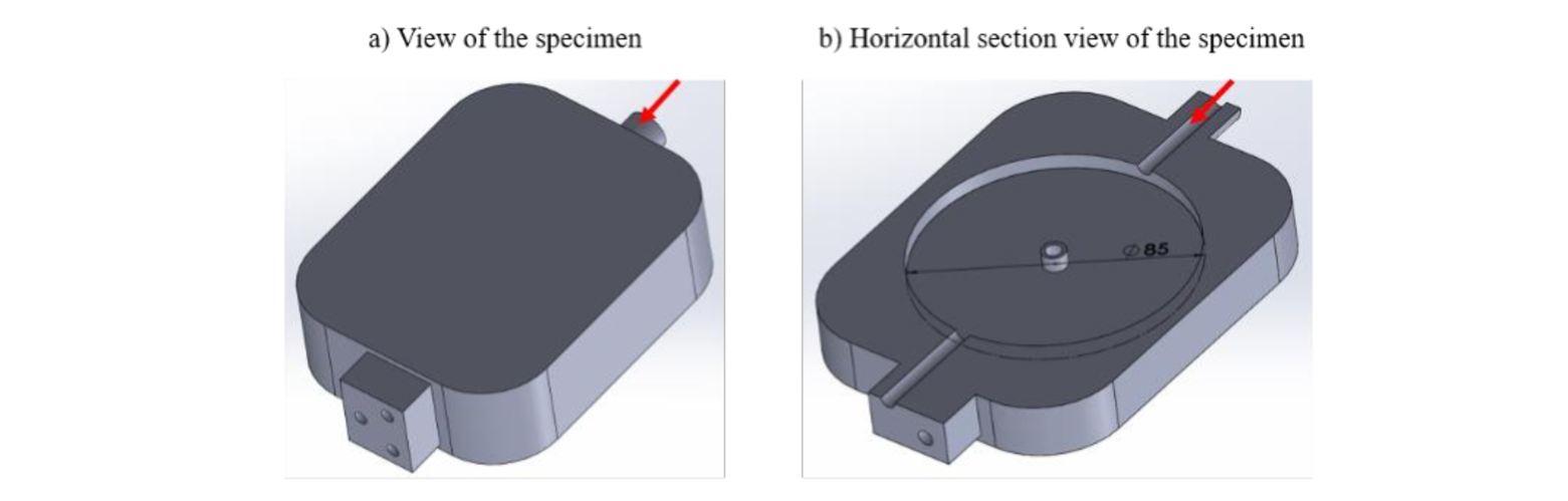
The cooling system was characterized by two spiral patterns (Fig. 2a-2b) connected each other thanks to a vertical channel, shown in the red box of Fig. 2a. In this way, the refrigerant fluid runs across the cooling channel from the top to the bottom side of the specimen. Fluid inlet and outlet sections are highlighted by red arrows in Fig. 2a. In Fig. 2c, a section plane splits into two equal parts the internal cavity, showing the most relevant dimensions of the geometry: every channel of the sample has a diameter of 5 mm and there is 1 mm clearance between the internal cavity and the cooling system and between every spiral of the cooling pattern.
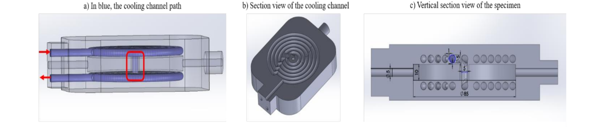
Fig. 2. Mould cooling channel geometry and section views.
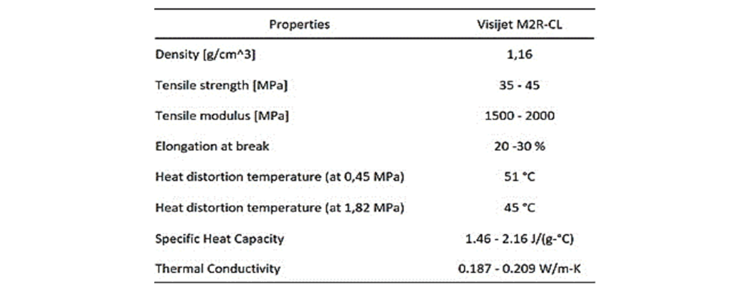
The specimen was 3D printed by using a Project 2500 printer produced by 3D System (see Fig. 3); the technology used was material jetting and the photosensitive material was the Visijet M2R-CL with the supports made of wax. Table 1 shows the main properties of the material.
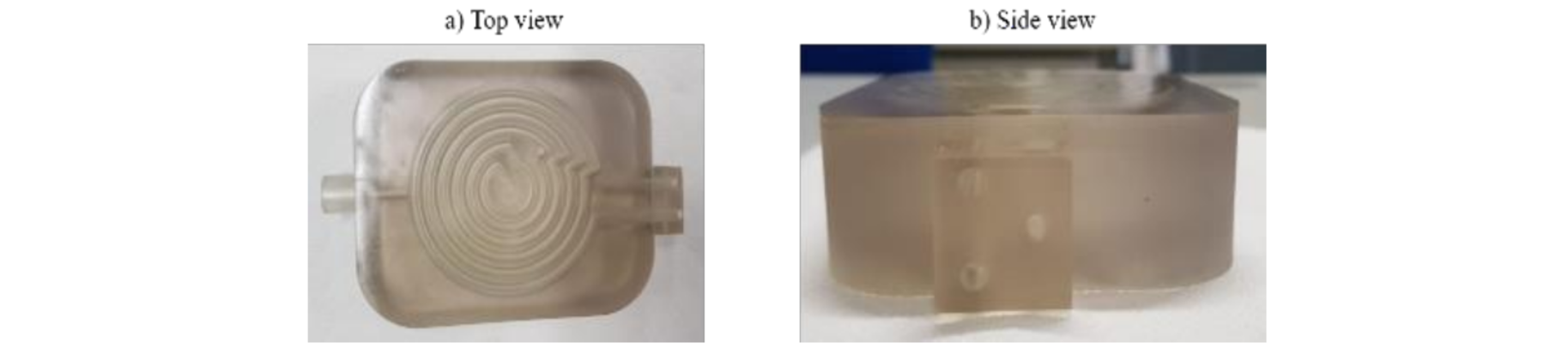
Fig. 3. Specimen 3D printed to perform the experiments.
Table 1. Visijet M2R-CL properties.
2.2 Experimental set up
The experimental tests campaign was performed by using the Armfield HT30XC test rig [6], that is an apparatus designed to measure small HX performance. This system has two different water circuits (see Fig. 4): the hot water one is a closed circuit.
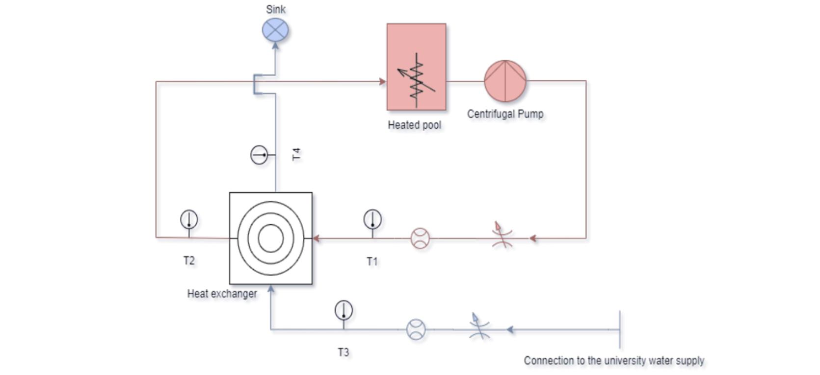
Fig. 4. Test rig schematic.
were the heat transfer fluid (HTF) is heated by an electric resistor at a selected temperature and moved by a pump; the cold HTF circuit is an open circuit that is connected to the laboratory water line. The two circuits feed the component that is under testing. Heat exchange performance are evaluated via temperature and volume flow rate measurements. Temperatures are measured with four type K thermocouples located at inlets and outlets of the water circuits.
The test rig calibration was performed balancing the heat flow exchanged between the two circuits. The sample considered was thermally insulated from the environment to minimize heat losses and the thermal power balance between the two fluids was performed using the average values of temperatures and flow rates. The heat flux imbalance was 0.04 W with respect to a thermal power exchanged of 38.3 W. Assuming perfect system adiabaticity, this leads to an error of 0.1%.
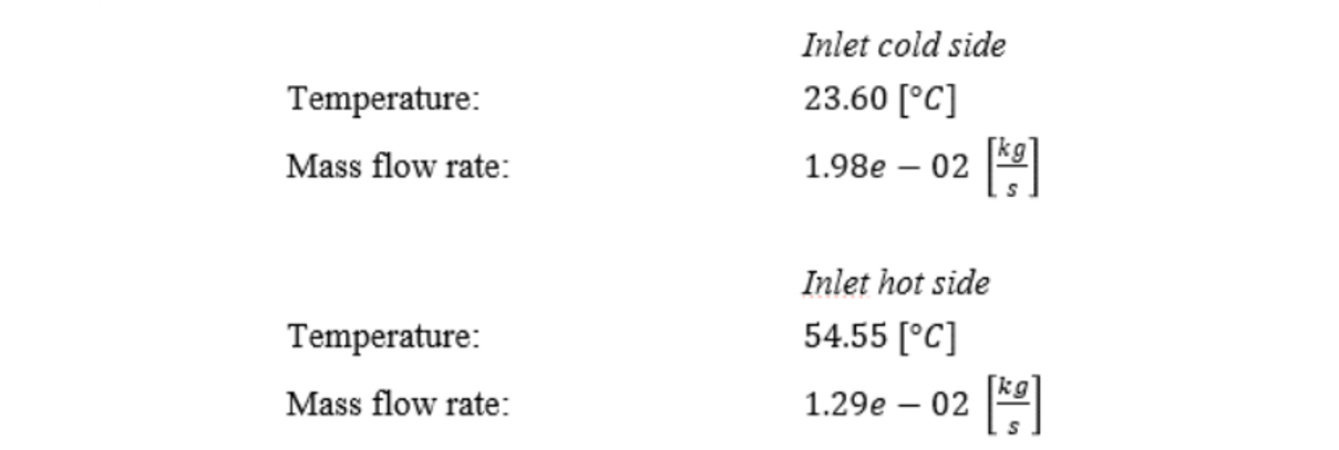
The test consisted in running the flow for about 1 h and 40 min, with temperature and volume flow rate measured each 2 seconds. This led to more than 3000 measurements collected for each variable; average and variance were evaluated. The variance is four orders of magnitude smaller than the average values. Therefore, average values were considered as measurements outcome. The test rig settings used for the experiments are reported in Table 2.
Table 2. Experimental test rig operating conditions.
2.3 CFD Modeling
The Computational Fluid Dynamics simulations were performed using ANSYS FLUENT 20.1 [7]. The flow regime analyzed is steady and turbulent and the Reynolds Averaged Navier Stokes approach was adopted. The 3D model included mass, momentum and energy conservation plus two equations for the turbulence model. Before performing the comparison between simulations and experimental data, some preliminary study on the best turbulence model and on solution grid independency were done.
Three different turbulence models were tested, namely k-epsilon RNG, k-epsilon Realizable and k-omega SST [8]. The computational mesh for these tests was designed so to have at wall a Y+ equal to one. A two-layer approach [9] was used for the near wall model of the two k-epsilon models. A comparison of the three simulations results brought to differences smaller than 0.1 % for the system in-out delta temperature. A closer look at the flow field showed several detachments and recirculation zones. For this reason, the k-omega SST turbulence model was selected as the most suitable turbulence model.
To verify the accuracy of CFD simulations, a mesh sensitivity study was carried out. The initial mesh, counting 7 million cells, was refined to 15 million cells leading to a decrease of 3 % of the calculated overall heat exchange. A further increase of the mesh cells number was not justified because the largely increased computational effort was not balanced by a corresponding significant accuracy enhancement. Therefore the 15 million cells mesh was used for the simulations (see Fig. 5). Thermophysical properties of the HTF, namely water, were modelled using temperature dependent functions. For coherence, the latter functions are identical to those implemented in the control software of the experimental apparatus. The simulation boundary conditions were set as specified in Table 2 considering the system external walls as adiabatic.
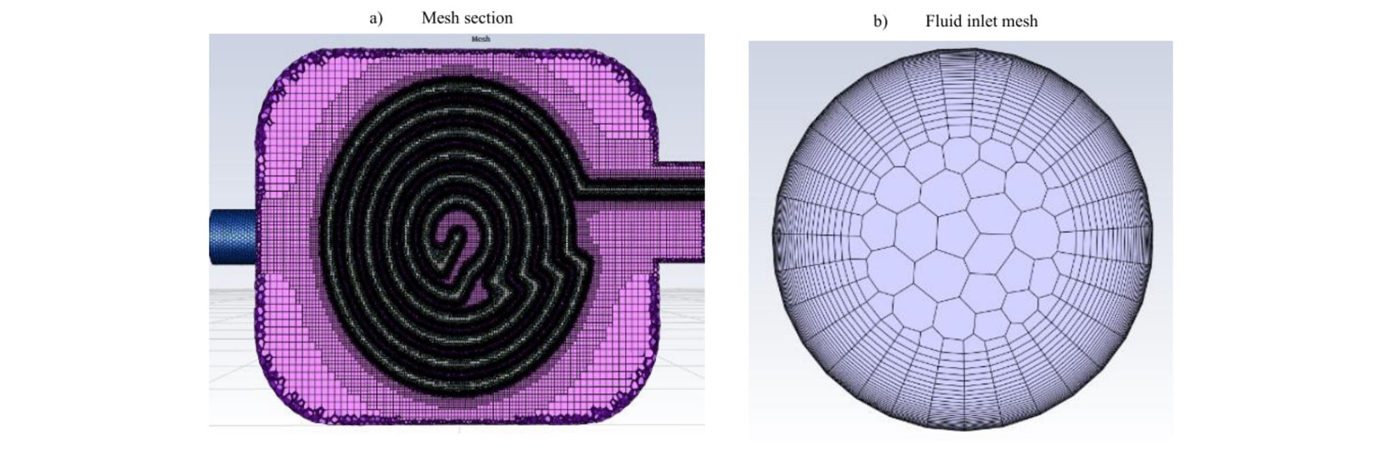
Fig. 5. Finer mesh used for the validation.
3 Results
Initially, the comparison between simulations and experimental data showed, for the heat exchange, a difference of 28 %. Being quite confident on the numerical approach numerical accuracy and after considering the possible errors induced by the turbulence model used in the flow regime of the experiments [10], the analysis was focused on possible effects of solid material thermal properties. The properties of the specimen material were provided with a possible range (Table 1), so, initially, it was decided to use average values. Bulk material thermal conductivity, was indicated as the property that, for a steady state experiment, could play a relevant role. Therefore, a parametric study was done varying this property, that, initially was set equal to 0.198 W/mK. This value was decreased down to 0.16 W/mK with a step of 0.01 W/mK. Fig. 6 shows how the error between simulation and experimental tests was progressively reduced: for a thermal conductivity value of 0.16 W/mK the error was lowered down to 3.5 %. A further decrease of the transport property just led to an inversion of the error sign.
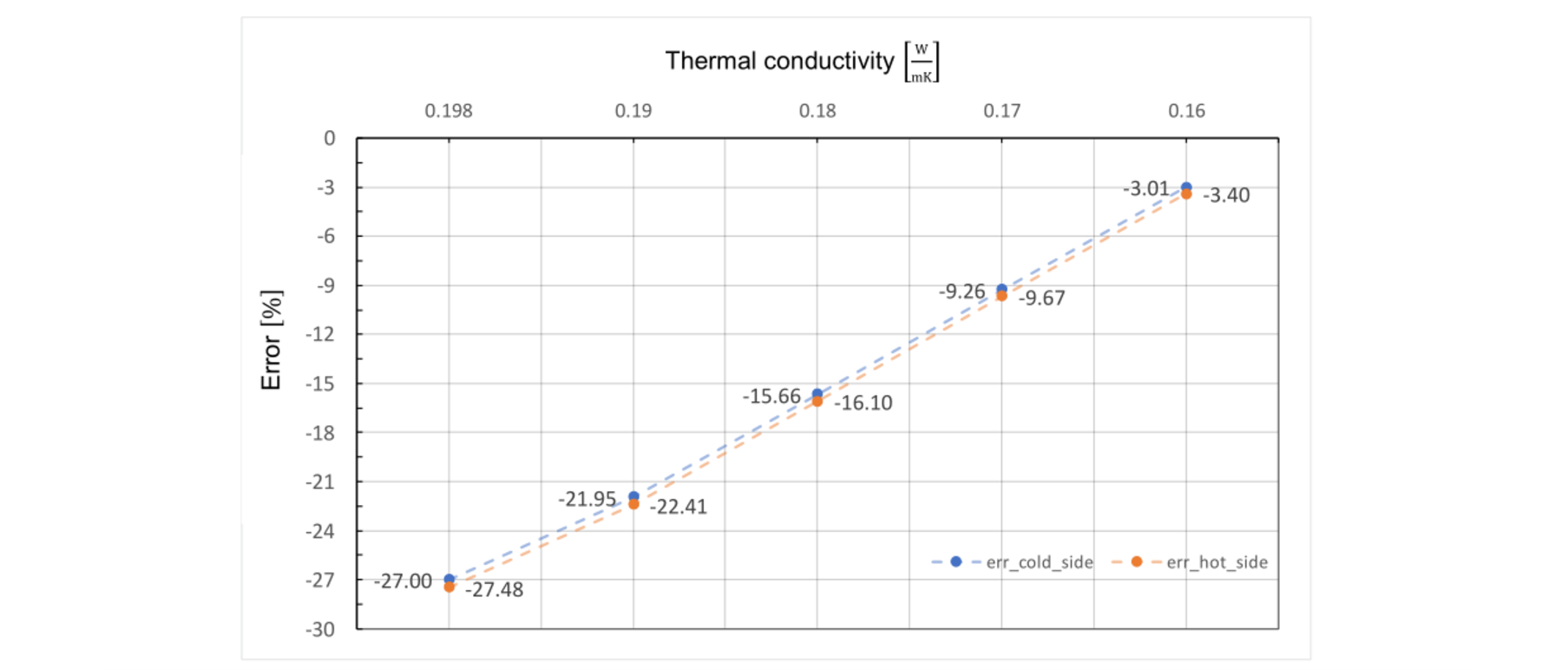
Fig. 6. Percent error between experimental and simulated temperature deltas (in-out).
Once the simulation model was validated, we analyzed the HX fluids dynamics behavior. Fig. 7 show the velocity magnitude contours inside the two cooling channels. In the Fig. 7a we can see how the fluid entering the injection pool from the left-hand side decreases greatly his speed due to the impingement with the vertical channel. Afterwards, the water accelerates again quickly toward the outlet duct. Fig. 7b shows the cooling pipe horizontal sections. The fluid velocity is almost uniform (green contours), although complex flows are generated near the steep turns. In these zones, we can notice that there are areas of stagnation, detachment, and reattachment of the fluid vein (blue contours), as well as rapid accelerations (red contours). The fluid dynamics differs for the top and bottom spirals due to the opposite rotation directions (anticlockwise on top and clockwise on the bottom).
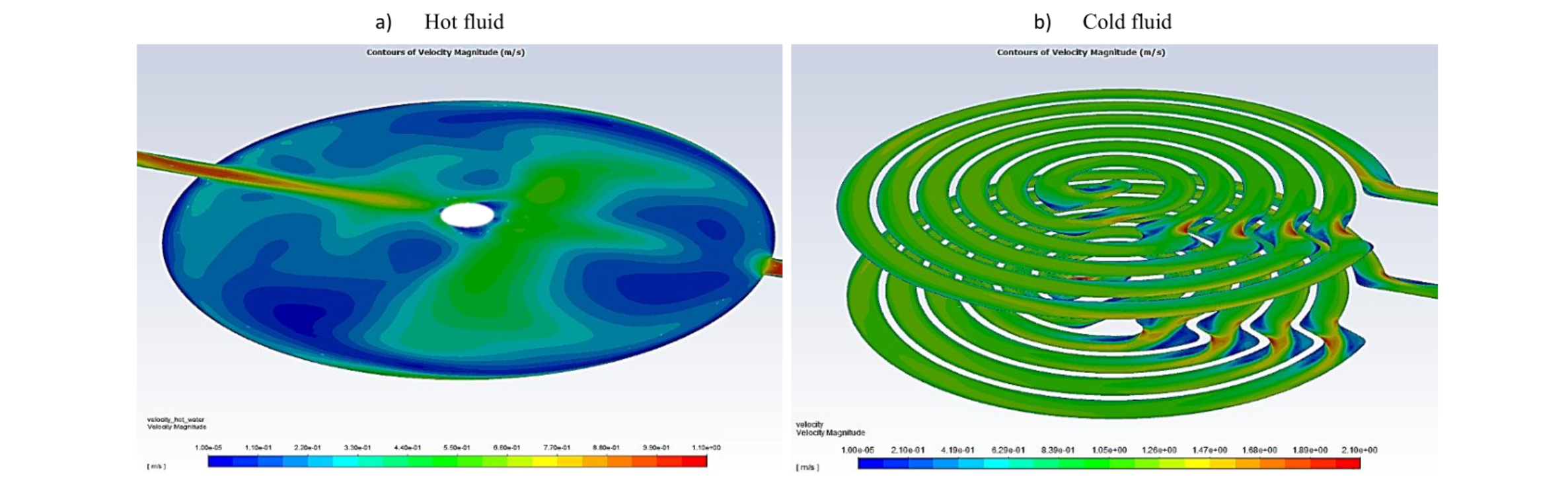
Fig. 7. Velocity Magnitude Contours [m/s].
Fig. 8 shows the temperature contours on three different sections. Fig. 8a shows the fluid inside the injection pool, whereas 8b shows the temperature contour inside the cooling pipe. In Fig. 8a the hot fluid enters from the left, while in Fig. 8b the cold fluid enters from the top.
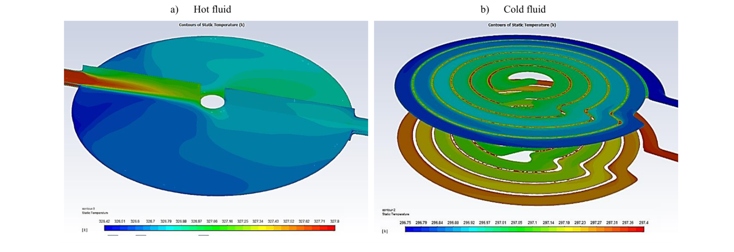
Fig. 8. Temperature Contours [K].
4 Conclusions
In this work, cooling channels for a mould were engineered via CAD, then tested via CFD. The experimental tests to validate the CFD results were done with a mould prototype realized with material jetting technology, an approach that ensures the best object quality without post processing operation. The test rig was designed to measure the heat exchange in the mould. The numerical simulations validation highlights that the correct selection of the mould material thermal conductivity is fundamental to achieve accurate results. Usually, datasheets provide only average values that, for polymers with very low transport properties, can jeopardize simulations accuracy. Therefore, a parametric study varying the solid material thermal conductivity was performed and showed that simulation vs experiments error can be reduced from 28 to 3.5 %. The CFD simulations, once validated, made possible to highlight all critical issues of the cooling flow and allowed to envisage possible conformal cooling performance enhancement.
