1 Introduction
Additive manufacturing (AM) technologies include all the processes that realize components by adding material layer by layer. Together with the AM, it has been developed the "Design for Additive Manufacturing" (DFAM), a guidelines collection that assists the designer to make the best use of these technologies. Thanks to the unique capabilities of the AM, these technologies can be applied in different areas, according to the process employed. AM can be even used to re-think the tools used in the manufacturing processes. Nowadays, in the milling operations, the weight of the milling tool greatly affects the motion speed of the mandrel, especially when a complex tool path must be performed. Thus, it is essential to realize lighter tools, without a significant decrease in the mechanical and production performances. Due to the limitation of the conventional manufacturing processes, the design of a milling tool is limited to a complexity of the external shape but in the cross section only full parts can be produced. Thanks to the topology optimization technique and the AM processes, it is possible to realize more complex part geometries and obtain more lightweight and high-performance tools. However, the topology optimization does not take into account the typical limits of the AM technologies. Thus the researchers tried to overcome this problem with the implementation of the AM processes constraints in this optimization technique. For example, the maximum printable overhang angle has been applied to the topology optimization [1-3], to reduce the use of support structures in the realization of the component. Moreover, a 3D printed part should allow the evacuation of unfused powder or support structures material from the internal areas of the component. Thus the LI QH et al. [4] study tried to apply a connectivity constraint to the topology optimization scheme, avoiding enclosed voids in the structure of the part.
However, this implementation process is still under development because most of the time the geometry given by the topology optimization has to be manually redesigned by the operator. To make easier and faster this step, clear rules and guidelines are needed, to help engineers in the design of the component. In this paper, to enlarge the knowledge about this topic, a topology optimization of a milling tool has been carried out. The results of the optimization have been little modified to minimize the use of support structures and allow the evacuation of the unused material. To verify the printability of the new geometry, the redesign milling tool has been realized with Selective Laser Melting (SLM) process.
2 Materials and methods
The objective of this research was the redesign of a milling tool, mainly used in the face milling operations. The geometry of the studied component is shown in figure 1.
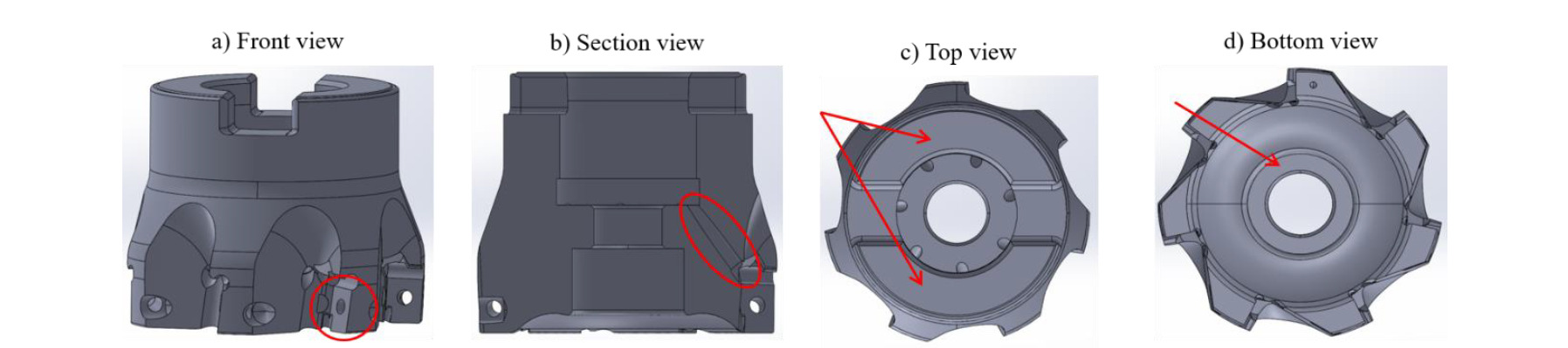
Figure 1: geometry and most important features of the milling tool.
The red circle in figure 1a underlines one of the 7 locations for the inserts. Figure 1b shows the channel for the refrigerant fluid, while in figure 1c the arrows point at the matching surfaces between the milling tool and the mandrel. These two components have been fastened together with a screw, whose matching surface with the studied component is shown in figure 1d.
The redesign of the milling tool has been reached through two steps:
-
topology optimization of the original milling tool;
-
minimization of the support structures required by the SLM process.
The topology optimization is a structural optimization which main goal consists of the optimal redistribution of the material inside a restricted design space. In order to obtain a correct optimization, it was essential to understand which regions of the milling tool were subjected to the greatest deformations and loads. Thus a static analysis of the component has been performed. The software employed for this goal was Altair Inspire. The model set-up of the static analysis consists of an assembly composed by the milling tool, seven inserts, the screws required to fix the inserts, seven cutting forces (the red arrows) and the supports applied to the model. Table 2 contains the values of the parameters selected to estimate the cutting force Ft, according to the specific cutting pressure model (ks0 model) [5]. This load was applied to every insert and acted on the red surface (4 mm length and 0,16 mm width) of figure 2a.
Table 1: parameters used to estimate the cutting force

Every cutting force was characterized by a direction perpendicular to a plane that connects the centre of the milling tool and the extremity of the insert where the force was applied (figure 2b).
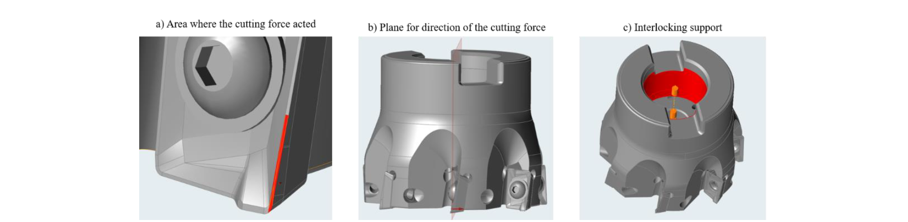
Figure 2: a) application area of the cutting force; b) plane used for the direction of the cutting force; c) interlocking support.
No relative movements were allowed between the milling tool and the mandrel thus the joint between the two parts has been simulated through an interlocking support, applied on the red surfaces shown in figure 2c. A pretension of 2400 N acted on the screws used to fix the inserts. The material used for the simulation was the 1.2344 alloy steel, whose mechanical properties are shown in table 2. These properties were found in literature.
Table 2: 1.2344 mechanical properties [6].
![Table 2: 1.2344 mechanical properties [6].](docannexe/image/3972/img-4.png)
In figure 3, the brown surfaces highlight the design space set for the topology optimizations: every part included in this space could be optimized and redesigned while the others had to maintain their original shape. The design space did not include the matching surface between the milling tool and the mandrel, the hole for the screw that fasten together these two components (figure 3b), the holes for the screws of the inserts, the surfaces where the interlocking support was applied and the seven inserts.

Figure 3: a) design space set for the topology optimization; b) hole for the screw of the mandrel.
In this research two main constraints have been set for the topology optimization: the maximization of the stiffness and a 70% reduction of the mass of the design space. Due to its working principles, the topology optimization created a raw geometry that must be smoothed. This operation has been performed in Solidworks, using its 3D modelling functions.
The smoothed geometry has been analyzed in the 3DExpert software to identify the areas that needed the support structures. According to the rules implemented in the software, the overhanging surfaces with a slope smaller than 30° from the horizontal direction and the down facing surfaces wider than 2 mm required these structures (figure 4). The support structures greatly affect the time needed for the post processing phase. Moreover, if these elements are needed in the internal surfaces of the milling tool they are hardly accessible or totally unreachable, so they can not be removed. Thus, to minimize the use of the support structures, small changes in the smoothed geometries have been made so that there were no areas with the characteristics shown in figure 5. All these changes will be discussed in detail in the next sections.

Figure 4: overhanging and down facing surfaces that required support structures.
In order to verify the mechanical performance of the new geometry, a static analysis has been performed with the same model set-up shown in figure 2. To check the geometry printability, the part was produced through the SLM process and the 17-4 PH was selected as material. Table 3 resumes the powder mechanical properties.
Table 3:17-4PH mechanical properties

3 Results
3.1 Static analysis of the traditional geometry
The results of the static analysis performed for the traditional milling tool geometry are shown in figures 5 and 6. In figure 5, the map of displacements highlights that the regions near to the matching surfaces between the milling tool and the mandrel are subjected to the smallest movements. Indeed, here there is an interlocking constraints that limited a lot the studied component. The locations of the inserts recorded the highest displacements because of the cutting forces that acted in these areas.
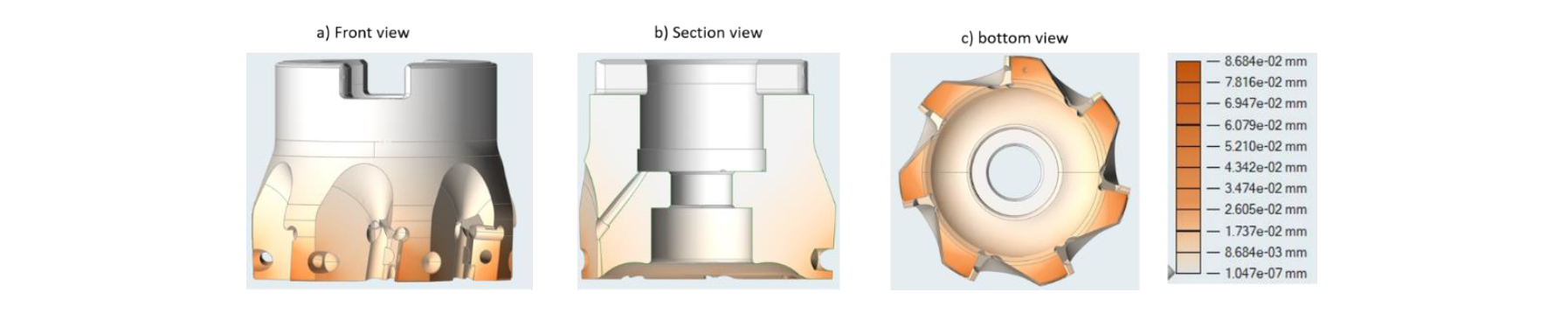
Figure 5: map of displacements of the traditional milling tool geometry.
The maps of the Von Mises stress shows that the contact areas between the milling tool and the inserts are subjected to the highest stress, proving that the locations of the inserts are the most stressed areas of the component.

Figure 6: maps of the Von Mises stress of the traditional milling tool geometry
3.2 Topology optimization and smoothed geometry
The results of the topology optimization are shown in figure 7. The brown surfaces represent how the optimization redistributed the material inside the design space. It is clear that this raw geometry could not be printed due to the high surface roughness, a lot of sharp edges generated by the optimization and the low dimensional accuracy.

Figure 7: topology optimization results. The brown surfaces represent the optimal distribution of the material according to the topology optimization.
In order to realize a geometry without these defects, the traditional milling tool has been modified with the help of the CAD software Solidworks. Based on the shape suggested by the topology optimization, a new design for the milling tool has been developed. Figure 8 shows the new smoothed geometry.

Figure 8: smoothed geometry of the milling tool.
3.3 Support structures minimization
The following images show every change made on the smoothed geometry to minimize the support structures. The yellow and blue areas identify the regions where the supports were needed.

Figure 9: section view of the milling tool before and after the geometry adjustment.
a) Section view before geometry adjustment; b) section after the adjustments.
In figures 9a inside the red box 1, the shape of the yellow regions have been turned into trapezoids (figure 9b). Thanks to this change, the downfacing surfaces of these areas were less wide than 2 mm and the supports were not necessary in these internal regions. Then inside the red box 2, the rectangular channel became trapezoidal, making needless the supports (figure 9b). Finally, the box 3 of figure 9b shows the adjustment of the milling tool contour underlined in figure 9a. This change brought to the realization of an internal channel that reduces the total weight of the tool. The octagonal shape allowed not to use supports in the realization of this feature. To evacuate the powder from this channel, six holes were created (Figure 10a). However, the circular shape required support structures, thus the holes assumed an elliptical geometry (Figure 10b).

Figure 10: adjustment of the holes used to evacuate the powder.
Since the circular channels for the refrigerant fluid needed support structures (red circle of figure 11a), their shape has been turned into dog bone ones (figure 11b).

Figure 11: geometry adjustment of the channel for the refrigerant fluid.
The surfaces highlighted in figure 12a have been modified to reach an octagonal shape (figure 12b) and avoid the use of supports in these areas, while the extensions of the surfaces shown in figure 12d reduce the curvature radius of the regions underlined by the red circles in figure 12c and make these part of the tool self-supporting.
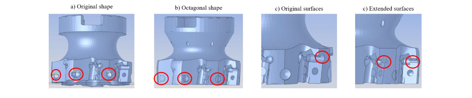
Figure 12: geometry changes in the locations for inserts.
Figure 13 provides an overview of the support structures required by the the milling tool after the “smoothing phase” and after the geometry adjustments. The front view of figure 13a reveals the smoothed geometry needed much more supports while in figure 13b, the section view shows that the use of these structures has been limited to separate the milling tool from the baseplate of the 3D printer and to sustain the matching surface between the milling tool and the screw for the mandrel.
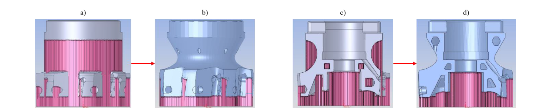
Figure 13: comparison of the two milling tool geometry
a) Front view of the smoothed geometry; b) front view of the adjusted geometry; c) section view of the smoothed geometry; d) section view of the adjusted geometry
3.4 Traditional geometry vs redesign geometry
The mechanical performances of the new milling tool are shown in figure 14 and in table 4. The maps of displacements and Von Mises stress show that the behaviour of the milling tool did not change even if it has a new shape: the location of the inserts are the most stressed areas and they are subjected to the highest movements.

Figure 14: map of displacement and Von Mises stress for the redesign milling tool
Table 4: mechanical performance comparison

Although the maximum displacement became two times greater, its absolute value was still small while the maximum Von Mises stress has been increased of 16,7%. Thus the mechanical performances of the new geometry are similar to the traditional milling tool, despite a 30% reduction of the mass.
3.5 Printed milling tool
The redesign geometry has been printed using the SLM process and the 17-4PH steel as the material. Figure 15 shows the new milling tool before and after having removed the support structures. The location for the inserts has been subjected to end mill operations to improve the surface quality.
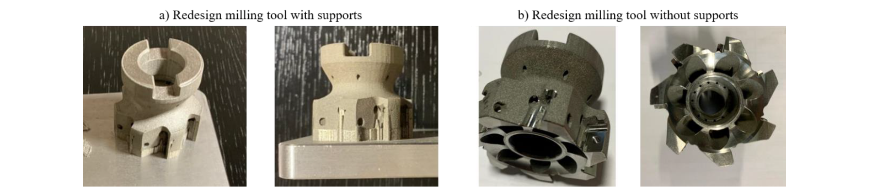
Figure 15: the printed milling tool before and after having removed the support structures
4. Conclusion
A new geometry for the milling tool has been designed thanks to the topology optimization technique. The new geometry results to be 30% less weighty but undergone to a higher maximum stress (about 17%). The higher decrease of performance highlighted is referred to the displacement that is doubled (from 0.04 to 0.08 mm) but is still acceptable for the machining environment. Moreover, the geometries adjustments introduced has minimized the support structures needed. Indeed, the new design has support structure perpendicular to the baseplate only to disconnect the milling tool from it and to sustain the matching surface between the milling tool and the screw for the mandrel. The new geometry has been successfully printed using the Selective Laser Melting printing process.
Acknowledgements
The authors would like to thank the Schneider tool s.r.l for providing the geometry of the original milling tool and for the willingness showed during the whole period of the research.
