1 Introduction
Introduced to the market a few years ago, the four-roll rolling process (4RP) is a new method for sizing of round sections to minimize cross-sectional variations which occur during hot rolling due to the elastic mill behavior and interstand tensions in continuous rolling mills [1]. The elongation efficiency in the 4RP is expected to be even better than in the well-established three-roll rolling process (3RP) [2]. Only few research activities about the 4RP are presently known, mostly carried out by the manufacturers of this type of rolling mills. Nardini et al. [3] described the general process and showed a reduced spreading characteristic of the 4RP by means of Finite Element calculations. Avellino et al. [4] showed a control system for the 4RP rolling block, where the working roll diameter was calculated according to the rolling theory of the 3RP [5].
These practical developments call for a theoretical treatment of the pass design problem for this new type of rolling mill. The well-known pass design principles as described by Lendl [6], Kennedy [7] and the author [8] shall be transferred to the 4RP.
In the present paper, first the special geometric features of the 4RP are discussed and basic formulae are given for the important geometric parameters. To enable pass design calculations, the spreading behavior of flat passes in the 4RP is examined using FEM calculations. On basis of the results obtained, an analytical spreading model is constructed using a process-specific correction factor to be implemented in a roll pass design model. The typical groove geometries (flat, round, opened round) are discussed and a method for geometric construction of the grooves is described.
The pass design problem to be addressed gains special complexity because all the grooves have two or more unknown parameters. To solve this problem, a simple single-variable iteration is insufficient. A numerical optimization routine must be employed to minimize the multivariate nonlinear problem. Each groove must fulfill two criteria: first an over- or underfilling must be prevented, second the cross sections should satisfy a predefined degressive pass schedule. From these two criteria, we can define an error function to be minimized by nonlinear optimization. With this procedure, the new model can automatically calculate a pass design for a given rolling task where the initial and final round sections, the desired number of passes and the nominal roll diameters are given as input values.
2 Pass geometry of a four-roll flat pass
First, we want to introduce the basic geometry of a flat pass in the 4RP, since it has specific differences from the well-known two-roll rolling process. The roll gap, as shown in Fig. 1, is formed by four rolls, which are inclined at an angle of 90 degrees relative to one another. The flat groove is uniquely identified by the inner radius IR and the roll gap s.
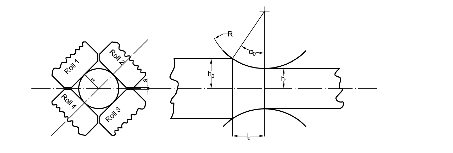
Fig. 1. Roll arrangement in a four-roll flat pass. Left: flat groove formed by four rolls with inner radius IR and roll gap s. Right: one of two roll gaps along a 45 degrees line with definition of geometric data, based on [9]
In contrast to the 2RP, we define the initial and final section heights h0 and h1 as shown in Fig. 1. Then, h1 is equal to the inner radius IR. For the contact length ld, we may define with the height reduction Δh = h0- h1 :

The nominal roll radius R is defined as the theoretical radius of rolls with a sharp 90° tip. The working roll radius of the flat pass Rwf is calculated using the exit height h1 (eq. to inner radius) of the flat pass and the roll gap s:

Another important quantity of the roll gap geometry is the bite angle α0. We may write:

The roll gap shape ratio (contact length over mean section height) must be defined in terms of Eqn. (4).

Note that these definitions differ from the 2RP because of the different definitions of h0 and h1. Also, a three-dimensional state of plastic deformation is always present due to the intersecting axes of the rolls.
The typical flat cross section in the 4RP is an octagon, where height and width of the section are defined as shown in Fig. 2.

Fig. 2. Definitions of the section geometry on a flat pass. h0: initial height, h1: final height. b0: initial section width, b1: final section width. bc0: initial contact width, bc1: final contact width.
We call the length of the inclined side the contact width bc, (the length which has contact to the roll surfaces), which is defined as:

Note that bc increases from bc0 (entry) to bc1 (exit) during the rolling process. In a general case for b > h, we can work out the cross section of the eight-sided polygon as:

For the special case of a regular octagon as shown as the initial section in Fig. 2 (b = h = IR), this cross section yields:

We should note that the section width cannot exceed bmax= √2. h, the case in which the octagon degenerates into a square.
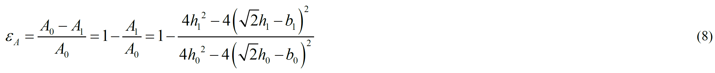
With Eqn. (6), the related cross-sectional reduction of the flat pass is expressed in the following way:
3 Section evolution and lateral spread in the four-roll rolling procedure
The pass design must be worked out in careful consideration of the spreading behavior of the four-roll rolling method. Finite Element calculations reveal that the lateral spread is mechanically restricted in the 4RP. Table 1 shows calculation results obtained using QFORM 9.0.10 [10] for flat passes in the 4RP with height reductions between 5% and 20%. The calculations were carried out for an initial workpiece temperature of 1000° C, workpiece material C55 (1.0535) and a constant Coulomb friction coefficient of μ = 0.35.
Table 1. Spread Calculations for flat passes with QFORM
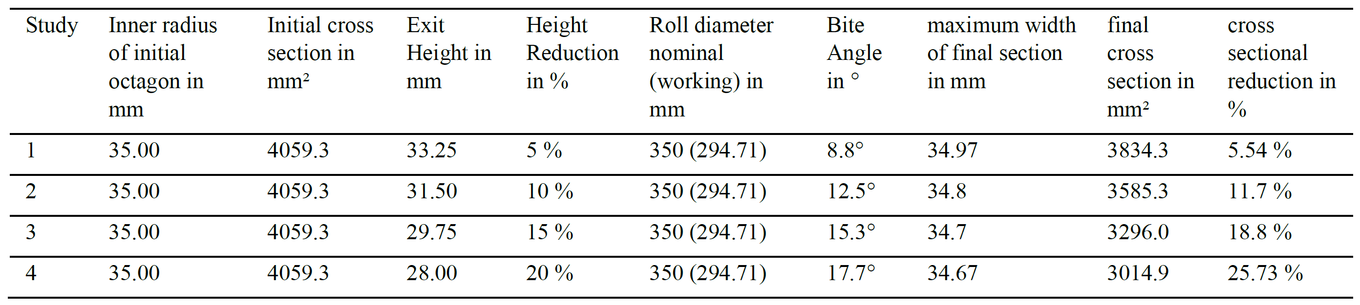
Fig. 3 shows the 3D model of the process in the QFORM simulation, as well as the final section contours which were obtained.
From these results, we can see that there is not only a very little lateral spread in the 4RP, but the section width is slightly reduced by the rolling procedure. Calculations carried out by Nardini et al. [3] came to similar results. In fact, the section evolution in the 4RP seems to be controlled by bulging of the free section sides rather than a lateral slip over the roll surfaces (see Fig. 3b).
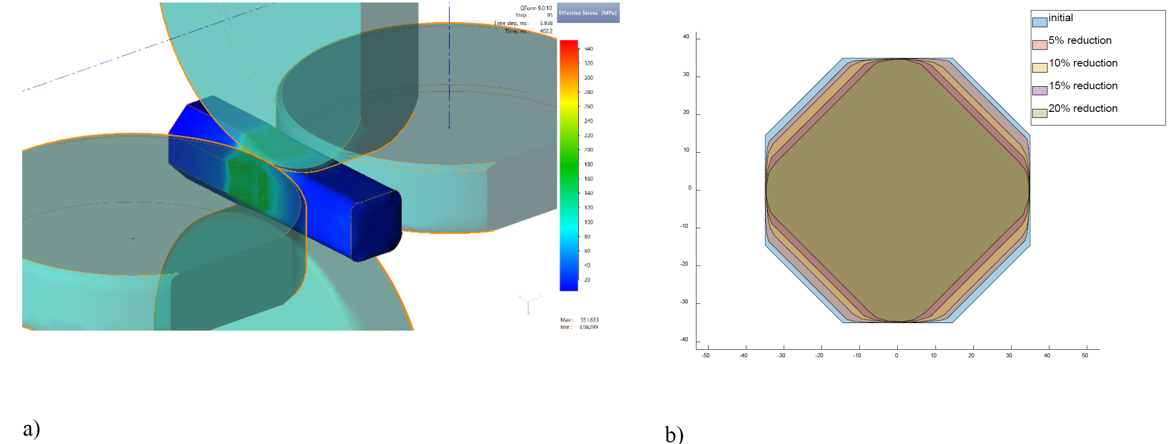
Fig. 3. FEM simulations for flat passes using QFORM 9.0.10.
a) Effective stress during a flat pass with 20% height reduction b) Initial section and calculated final sections for all height reductions considered.
A direct validation of these results cannot be shown currently due to the unavailability of a laboratory four-roll rolling mill, since the 4RP is not yet commonly established and the desired machinery is hardly available. However, a study carried out by Xie et al. [11] has shown that the side formation due to edge bulging can generally be predicted with high accuracy in the 2RP using the finite element method.
Based on the FEM results, we now want to find a method of calculating the lateral spread with an elementary method by transfer of the established spread equations for the 2RP to the 4RP. The general spread model is shown in Fig. 4 for a flat pass in the 4RP. The shaded area is the displaced area Av. A fourth of this area is displaced by each of the rolls. A part of the displaced area is assumed to return as the reappearing area Aw, which is equally distributed over the four roll gaps.
Fig. 4. Simplified spread model for the 4RP. Av: displaced area, Aw: reappearing area. Δb: change of width Δh: height reduction.
The spreading model by Marini [12] has gained high appreciation because it has proven to be reliable and precise for flat passes in the 2RP [13]. However, referring to the FEM results given above, the spread calculation must be corrected for the 4RP.
A typical spread model for the 2RP, is a function of geometry and friction:

A 2RP spread model in this formulation takes the height reduction from h0 to h1, distributed symmetrically over two rolls and returns the total width increase b1-b0 of the section distributed equally over two roll gaps (left and right to the section). To transfer this spreading model to the 4RP, we must formulate it in terms of the height reduction contribution of one roll and width increase contribution of one roll gap.
The width equation for the 4RP is now given in Eqn. (10).

From these considerations, we would generally expect a reduced spread behavior with a correction factor of 0.5 in the 4RP compared to the 2RP. However, a direct comparison of the section evolution in different rolling processes (2RP/3RP/4RP) is not very straightforward, because the elongation efficiency is influenced by many other effects which are different in the process variants (different roll diameters, generally different pass design principles).
To fit the analytical spread model to the data gained using the FEM simulations, we introduce a correction factor fC. In the four rolling passes considered above, the mean correction factor was determined as fC = -0.35. With this corrected spread model, the spread for the flat passes can be calculated with sufficient accuracy using the analytical model.
For the final width b1, we may write:

4 Groove geometries for the four-roll process
In the present analysis, three basic geometries of grooves are used. Fig. 5 shows a graphical representation of these groove types.
Fig. 5. Principle groove designs for the four roll rolling process. Left: flat groove, center: non-opened groove, right: tangentially opened groove.
The simplest groove is the flat groove as shown in the leftmost part of Fig. 5. Here, all roll barrels are flat and no grooves are cut into them. A typical four-roll roll flat pass would deform an initial octagon shape into another octagon by decreasing its height h. The width b of the octagon could be increased or slightly decreased by the rolling process.
The next geometry to be used is the non-opened circular arc groove, which is shown in Fig. 5 (center part). The groove is described by the main groove radius R1 and the inner radius IR. For the special case of R1=2d, a round groove is obtained. We call the following factor the related eccentricity e of the groove:

By choosing an eccentricity factor of e > 1, oval-shaped groove geometries can be obtained for preliminary passes, prior to the final round section. Although there is some freedom concerning the rolled shapes using this groove type, a further development of this groove can be achieved using the tangentially opened groove as shown in the rightmost part of Fig. 5. Here, a round groove with 2R = d does not represent a circle, but at a certain angle α, the circular arc is continued by a tangential line. This method has advantages for the guidance of the initial sections and provides a better rolling stability to avoid rolling faults by over-spreading.
5 Computational generation of pass geometries and data handling
For a precise pass design model, the groove and section geometries shall not be described in a parametrized way, but by their actual xy-coordinates. To do so, the geometrical construction of the grooves must be implemented. This will be shown for the tangentially opened groove as a general example.
In Fig. 6, a quarter section of the first quadrant of a typical opened groove is shown.
Fig. 6. Construction method for the opened four-roll groove (see Fig. 5).
First the roll gap lines g1 (horizontal roll gap through P2) and g2 (vertical roll gap through P7) are defined, as well as the 45 degrees line g3. The lines from the origin to the end points of the arc with radius R1, g4 and g5 are defined as passing through the origin and inclined at angles (45°± α).
The center point of the radius R1 (at the intersection with g3) is calculated as xC = yC = d/(2.√2) – R1/√2.
At P4 and P5, the radius R1 is continued by the tangential line P5-P6 or P4-P3. The transition radii R2 are then constructed between the previously calculated lines. When the construction of the quarter section of the groove is finished, it is mirrored into the other three quadrants. The completed contour is then transformed in a discrete set of points with their x- and y-coordinates, as shown in Figure 7 for one example with given data. Finally, the groove is represented by a data structure containing all x- and y-coordinates from the starting point (red circled in Fig. 7) in a clockwise direction. These x and y coordinate vectors are used for further computations.
Fig. 7. Numerically computed groove contour for an opened four-roll groove.
Diameter d = 20 mm, radius R1 = 15 mm, angle α = 40°, roll gap s = 2 mm.
6 The equivalent flat pass for the four-roll process
To enable the calculation of the lateral spread and other import figures for the section deformation, an equivalence method must be constructed for the four-roll rolling procedure. The proposed equivalence method is based on considerations by Lendl [6], which were transferred to the three-roll rolling process by Overhagen and Mauk [5].
The basic idea of the equivalence method is to treat only the parts of the sections, which are under direct influence of the rolls. According to this theory, the hatched areas in Fig. 8 for the initial section (left) and the final section (right) are considered. The Lendl width bL is the distance of the two cutpoints on each roll between the initial section and the groove contour (see Fig. 8).
An important feature of this method is that the equivalent cross section of the final section is independent of the actual lateral spread in the pass. After the section areas A0L and A1L have been found by a numerical-graphical routine, we can write for the mean entry and exit heights of the section pass (which is now transferred into a flat pass):

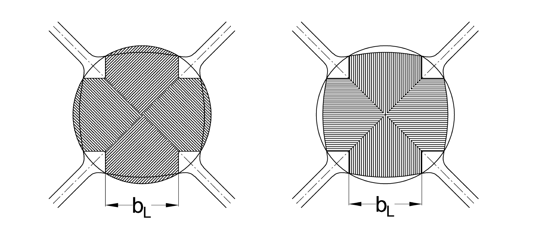
Fig. 8. Equivalent cross sections on a four-roll pass. bL: cutpoint distance or “Lendl width”. Left: Shaded area A0L, Right: Shaded area A1L.
The working roll diameter for the 4RP is calculated in accordance with [5]. After this transformation, the spread can be calculated as in a four-roll flat pass with the procedure described in section 3.
7 Pass sequence design
A typical rolling task would be to reduce an initial round section to a smaller round section in several passes. To ensure a stable rolling process and to achieve close tolerances, a degressive stepping of the pass reductions is appreciable. This is done using the following technique, in which the total elongation λtot = A0 / Ae is expressed as a mean elongation per pass, raised to the power of the pass number N. The mean elongation per pass is then defined in the following way:

Therefore, the total elongation would be achieved in N passes with the mean elongation λm in each pass. Based on this approach, we want to vary the per-pass elongation as to approach a degressive reduction distribution. For each pass number i, we choose a degression factor fi as given in Eqn. (15):

Generally, fi must be inverse to fN+1-i .This condition is met by fi = Zyi with yi = (N+1)/2 – i .
We can write:

In this equation, Z is a degression constant with Z > 1 for a degressive pass schedule.
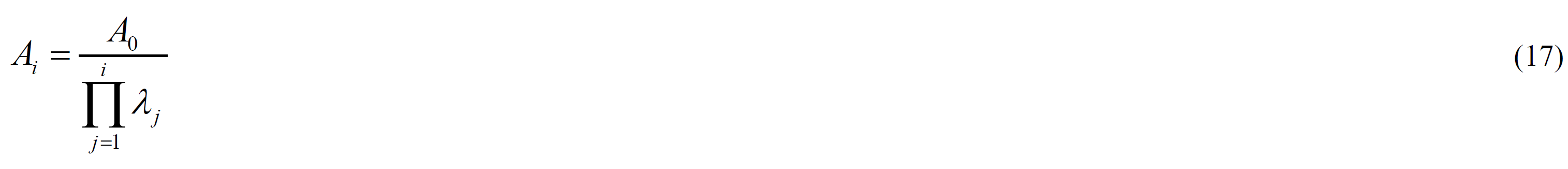
Once the pass elongations have been calculated by means of Eqn. (16), we can easily find the cross section of the rolled product after pass i by evaluation of the following equation, using the initial cross section A0 and the per-pass elongations λi :
8 Automated optimization of groove geometries
After the desired cross sections for each pass have been calculated with the procedure described in the preceding section, for each pass a groove geometry must be found which generates a cross section as calculated by Eqn. (17). The groove should also fulfill a predefined filling ratio, i.e., an overfilling of the groove must be prevented. Mathematically, this is a problem of nonlinear optimization in which a set of unknowns (geometrical parameters of the groove) are adjusted to minimize an error function (the norm of the section area and filling errors). This error norm is defined as:

Here, bact is the actual section width calculated in the current iteration, bf is the width-on-face of the groove and f1 is the desired filling ratio of the groove. Aact is the actual sectional area calculated in the current iteration and Adesigned is the designed sectional area calculated by Eqn. (17).
The problem is solved using the algorithm fminsearch of the software package MATLAB 2020b, which uses the simplex search method [14]. This process is repeated for all subsequent passes to find the optimized groove geometries.
9 Calculated pass design
As an application example of the pass design model, a four-pass sequence with an initial section diameter of 24 mm and a final diameter of 20 mm is considered. Throughout the rolling process, tangentially opened grooves ought to be used.
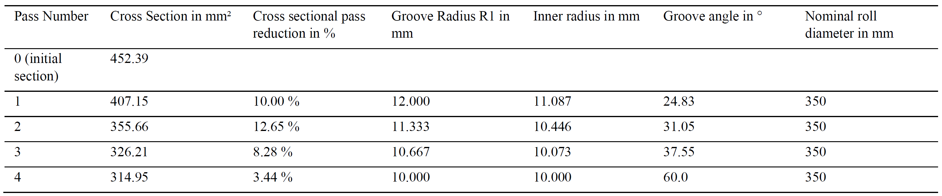
A degressive pass schedule was calculated with a degression constant of Z = 1.05. The groove radii were designed in a linear relation to the cross sections of the respective sections. The groove angles and diameters were optimized numerically to fulfill the specified cross sections and filling ratios. The aimed filling ratios were 97% for the preliminary passes and 99% for the final pass, which were reached with errors of less than 10-6. Table 2 gives an overview about the pass design results obtained for a nominal roll diameter of 350 mm.
Table 2. Calculated pass design for 24 mm to 20 mm in four passes
10 Conclusions and Outlook
The present paper outlines the process of pass design for a four-roll rolling block which can be used for the sizing of round sections. A special complexity arises because the pass design is not an alternating sequence of main and intermediate grooves. Therefore, each of the grooves to be determined has at least two unknowns. In the present approach, the groove geometries are found by numerical optimization of an error function, minimizing deviations of groove filling and cross sections from their desired values. Based on FEM calculations for flat passes, a correction factor for the spread calculation was introduced. Internally, the spread equation of Marini is used in the model. As a four-roll rolling mill in a laboratory scale is unavailable, experimental validation of the presented FEM results could not be accomplished at the current state. Works carried out by other researchers indicate that the side formation can in general be predicted accurately using the FE method.
It may be concluded that the pass design problem can be addressed adequately using the numerical optimization algorithm. The spread calculation with elementary methods for the 4RP is not yet completely solved. The correction approach of the current paper could be extended for a wider range of rolling parameters, but further series of experiments need to be conducted to examine the spreading behavior and the side-formation characteristics of the four-roll rolling process more in detail.
Acknowledgements
The author wishes to thank the University of Duisburg-Essen for providing the necessary environment to carry out the research activities that led to the present paper. This work did not receive any third-party funding.
