1 Introduction
The naval industry is a sector that involves the engineering of complicated structures, with sophisticated designs capable of enhancing the entire boat performance. Both aesthetic and technical needs require particular attention to the choice of materials used. The progress of naval artillery has imposed the use of steel for most of the constructions, leaving the minor shipping sectors to timber. However, it must be noted that the basic requirement that each material must possess is resistance to corrosion.
The use of steel has several advantages including: weight reduction of about 40% compared to a similar wooden structure, simplicity of structuring and therefore greater load capacity, greater impermeability of the planking and absence of caulking, as well as greater durability and ease of repair [1]. In recent years, aluminum has also entered predominantly in the shipbuilding industry. Thanks to its high strength and light weight, it permits the creation of highly performing and extremely durable boats. The use of light weight alloys, usually magnesium-based aluminum alloys for the naval field, is limited to the construction of light and fast hulls components as well as of the superstructures of large ships. In this way, it is possible to reduce the weight on the upper part of the ship thus bringing down the center of gravity and enhancing the overall stability of the ship itself. The specific weight of aluminum is lower than the one of steel, indicating that a vessel made of aluminum alloy will have a significantly lower weight. In fact, from the point of view of designers, the increase of interest towards light weight and highly resistant alloys to build ship hulls is mainly dictated by the possibility of a significant reduction in structural weight of the entire vehicle. This favors the movement of the vessel at higher speeds or a reduction in fuel consumption contributing eventually to a reduction in pollutants.
Dissimilar joints between steel and aluminum have been of great interest for the scientific and industrial worlds. Examples are the welding between aluminum and steel in the automotive field, which are able to guarantee both the reduction of the weight of the structure and the increase in the impact resistance of the vehicle [2] and in the naval field where the use of aluminum in superstructures allows the lowering of the center of gravity for better stability of the ship. Welding of steel to aluminum can be obtained using different techniques, including fusion welding processes. Zhang et al. [3] used a modified MIG process, called Cold Metal Transfer (CMT) to join aluminum and zinc coated thin steel sheets with Al-Si alloy filler under argon protection. Sierra et al. [4] joined a AA6XXX aluminum alloy to a carbon steel through key-hole laser welding. The same authors compared the integrity and mechanical properties of joints produced by either laser welding or GMAW [5].
The above studies demonstrates that fusion welding of aluminum/steel joints is a difficult process. Due to the significant difference in the thermo-mechanical properties of the different base materials, selecting proper welding parameters is problematic and the process windows are extremely limited. Many different factors, such as complex weld pool shapes, segregation, inclusions, porosities and inhomogeneous microstructures severely affect the quality of such welds [6]. Moreover, the fact that iron has a very low solubility in Aluminum, contribute to the occurrence of detrimental effects on the weld joint strength due to the formation of extremely brittle intermetallic layers [8].
In recent years, the need to create effective lightweight structures usable in various industrial sectors has led researchers to develop new welding methods, such as Friction Stir Welding, allowing the joining of materials with dissimilar characteristics [9].
FSW is a solid-state joining process in which the heat and plastic deformation induced by the rotational and translational movement of a tool are used to weld two or more sheets. Unique advantages have emerged from the use of this technology, as compared to traditional welding methods, which allow the overcoming of many of the metallurgical problems that arise when joining materials considered ideally non-weldable: as the working temperatures reached during this process are lower than the melting temperatures of the materials, many of the defects that arise at the moment of solidification are avoided and the thickness of the brittle intermetallic compounds (IMC) that are formed at the interface can be reduced [10]. Through FSW it is then possible to use aluminum alloys and steel in the same structure [11]. This combines the high strength, good creep resistance and formability of steel with the low density, high thermal conductivity and good corrosion resistance of aluminum in a hybrid structure [12]. FSW also represents a valuable solution to avoid the occurrence of the previously mentioned defects occurring during fusion welding.
A few studies have demonstrated the effectiveness of FSW for the low alloyed steels used in the naval sector [13]. Kankol [14] analyzed HSLA-65 steel, in this study the characterization was carried out using Charpy, hardness and tensile test. The results indicated that FSW appears to be very effective for welding ferrous alloys in shipbuilding. Coelho et al. [15] joined two different grades of high strength steels to AA6181-T4 in a butt joint configuration (an offset was given to the tool towards the aluminum plate side). They found similar resistance for the joints obtained with the two material configurations, with a predominant role of the morphology of the Heat Affected Zone (HAZ) and Thermo-Mechanically Affected Zone (TMAZ) of the aluminum plate in respect to steel ones. Chen at al. [16] studied the effect of pin penetration on the shear strength of lap joints made out of 6 mm thick AA6060 and 2 mm thick mild steel. Maximum strength was found for a pin height designed to be as close as possible to the steel sheet during the process with no penetration into it. Lower penetration promoted the formation of defects in the weldment, while excess of penetration of the pin tip into the steel sheet created an excess of intermetallic, which reduced the joint mechanical strength. On the contrary, a similar study by Wei et al. [17] showed different results. Lap joints, obtained joining 3 mm thick AA1060 and 1 mm thick austenitic stainless steel, were produced with varying tool pin height and welding speed. The major finding of their research was that the use of a cutting pin, i.e., a pin that penetrates into the bottom steel sheets, results in enhanced shear strength due to the presence of saw-toothed structures.
From the above reported studies, it arises that there is still uncertainty in the determination of the best welding conditions when dissimilar steel-aluminum joints are considered. In this paper the authors present the results of a research focused on the engineering of the FSW process of dissimilar joints made out of AA5083 H321 aluminum alloy and naval steel DH36 plates having a thickness of 6 mm. The main welding parameters and the geometry of the tool were varied and their effect on the main mechanical properties of the obtained joints was evaluated identifying a proper process window.
2 Materials and experimental methods
The FSW experimental tests were performed on shipbuilding steel DH36 and aluminum alloy AA5083 H321 plates, both having thickness of 6 mm. The main chemical and mechanical properties of these metals are reported in Table 1 and Table 2.
Table 1. Chemical compositions of the examined DC steel and AA6016 alloy.
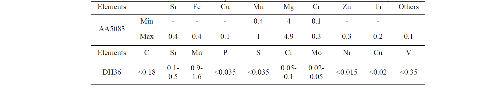
Table 2. Main mechanical properties of the examined DC steel and AA6016 alloy.

The tests were carried out using an ESAB LEGIO machine (Fig.1a) using a tool plunge of 6 mm at a tilt angle (θ) of 2.5°. The machine used is a 3-axis force controlled specific for Friction Stir Welding having maximum rotational speed of 2500 rpm, feed rate 2000 mm/min and force applicable up to 25 kN. In order to ensure the same plunge along the weld, a force control on the stirring head was set on the machine. Both the top and bottom sheets were reduced into rectangular specimens 100 x 100 mm in length and width respectively. The used clamping fixture is shown in Figs. 1c and 1d. For the tests, a lap joint configuration was considered with steel as the bottom sheet and aluminum as the top one. An overlapping between sheets equal to 32 mm was assigned. A W25Re (tungsten 75 %wt., rhenium 25 %wt.) tool was used, characterized by shoulder diameter equal to 16 mm and conical pin, 6 mm in height, 6 mm in major diameter, and 30° in taper angle. Figs. 1b and 1e, show the shapes and geometrical features of the tool adopted for the tests.
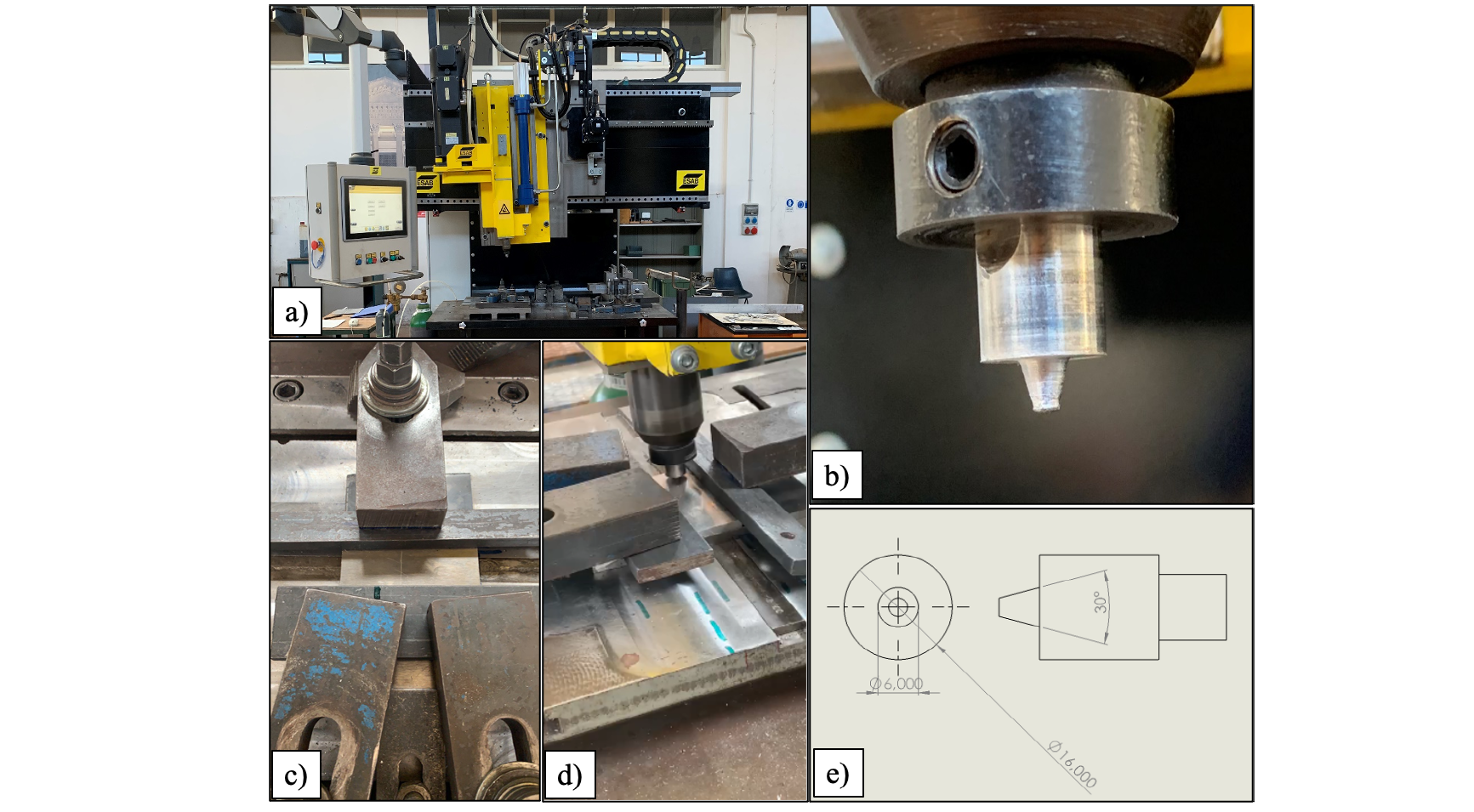
Fig. 1. (a) ESAB Legio machine, (b) Pin tool shape, (c, d) views of the clamping fixture and (e) geometrical parameters of the tool used
As far as the process parameters are regarded, the tool rotation and the feed rate were varied from 350 up to 1300 rpm and from 25 up to 100 mm/min, respectively. In this way, 12 different process conditions were investigated. Table 3 illustrates the combinations of the technological parameters used.
Table 3. Technological parameters used.

From each test, three different specimens were obtained (Fig.2) in order to investigate the joint performance. For the mechanical characterization of the joints, shear tests (using Galdabini Quasar 600) and micro-hardness measurements (using Remet HBV30A) were carried out. Regarding the micro-hardness measurements, the indentations were carried out with a 500 g weight for 30 sec along the joint thickness, with a distance of 0.5 mm between two consecutive indentation. Each test was repeated thrice, and no significant variation in the results was observed.

Fig. 2. (a) LAP configuration, (b) specimens cut for the analysis
3 Results & discussions
Fig. 3 shows the weld seam of both sound joints and those that manifested some macro-defects (i.e., tunnel defect inside the weld bead or a superficial material flow defect on the top sheet).
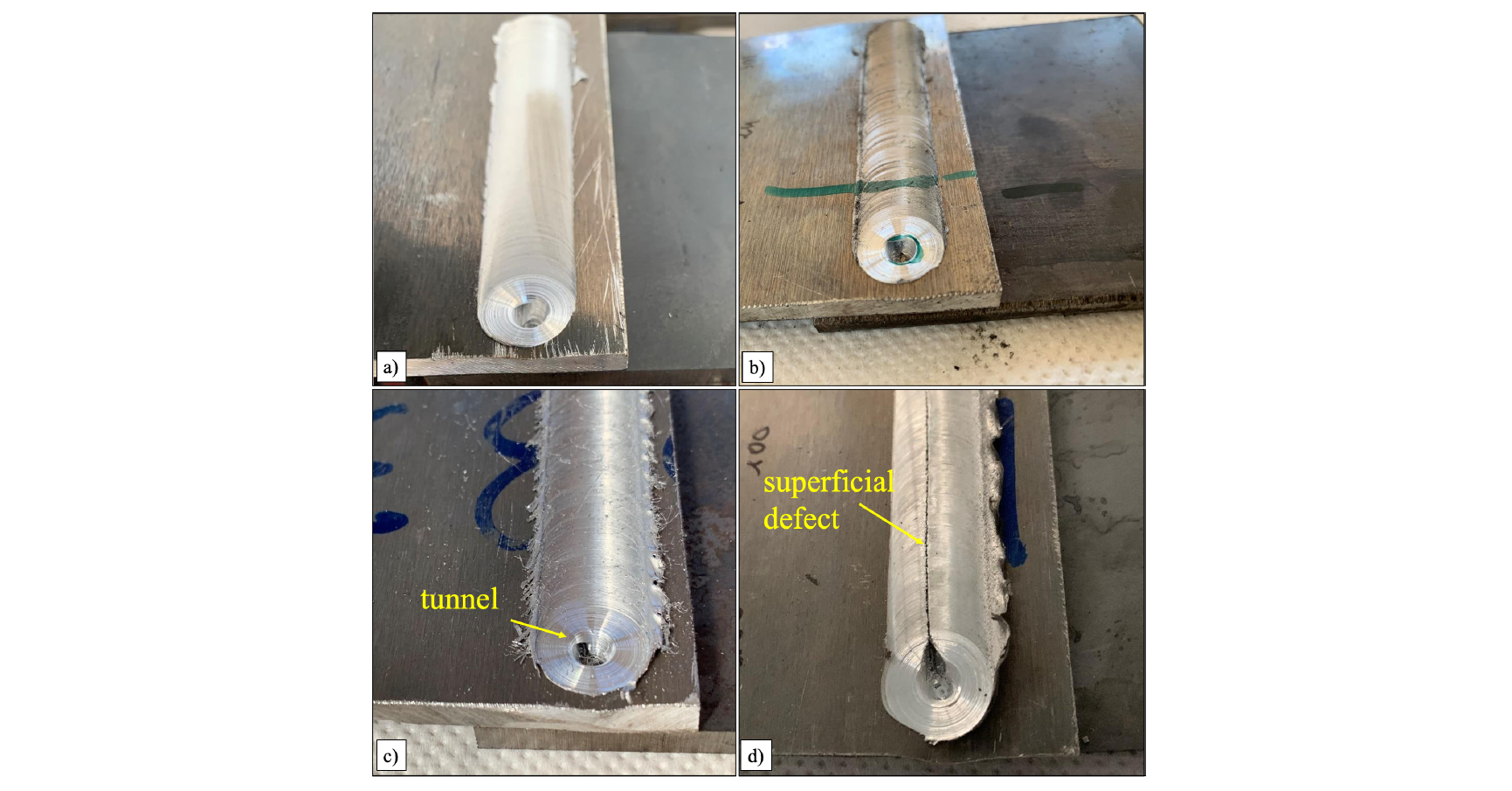
Fig. 3. Specimens obtained for different welding conditions: (a) 350 rpm – 25 mm/min, (b) 500 rpm – 25 mm/min, (c) 900 rpm – 100 mm/min, (d) 1300 rpm – 100 mm/min
As it can be seen in Figs. 3a and 3b, referred to welds obtained with rotational speed of 350 rpm and feed rate of 25 mm/min and a rotational speed of 500 rpm and feed rate of 25 mm/min, respectively, no defect was observed. On the other hand, the weld obtained with a rotation speed of 1300 RPM and feed rate of 100 mm/min (Fig. 3d) was characterized by visible macrodefects. For this process condition, no HV test was conducted. Similar considerations can be made for the joint characterized by a rotational speed of 900 rpm and feed rate of 100 mm/min, for which the tunnel macro defect occurred. It is worth noting that the abovedescribed flow defects were observed for each of the three repetitions made for each process condition.
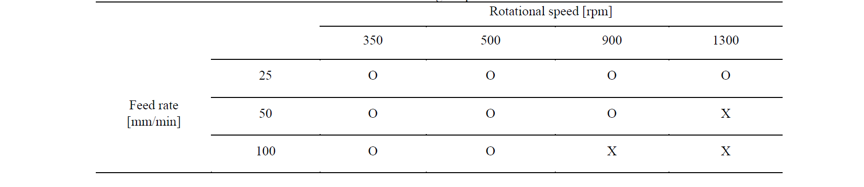
Tab 4 shows the process window obtained. The symbol "O" was used to highlight the parameter sets that resulted, from a visual inspection, in a sound joint, while the process conditions for which proper solid bonding was not obtained were indicated using an "X" symbol. It can be seen that only a few process conditions resulted in macroscopic defects.
Table 4. Technological parameters used
The results obtained from the shear tests, in terms of failure load per unit of weld length, are reported in the following Table 5. With the terms CF (cutting failure), it is indicated a specimen broken during the clamping for cutting.
Table 5. Shear test results
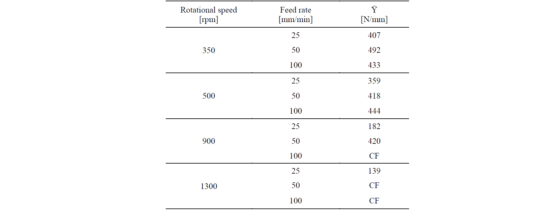
The maximum of Ῡ (492 N/mm) was obtained for the weld characterized by rotational speed of 350 rpm and feed rate of 50 mm/min, corresponding to the second lowest heat input among the weld conditions considered in this study. The minimum of Ῡ (139 N/mm) was obtained for the weld obtained with rotational speed of 1300 rpm and feed rate of 25 mm/min, which, in turn, is the weld characterized by the largest heat input. Another important aspect regards the rotational speed used: with low rotational speed, i.e. 350 and 500 rpm, the results obtained have lower variability (and generally higher strength of the joint is observed) while, increasing the speed to 900 and 1300 rpm, larger variability and lower strength is found. Besides, for some process conditions, proper welding conditions could not be even reached. It is also observed that with rotational speed of 900 rpm and feed rate of 50 mm/min, the weld reached a high Ῡ value i.e. 420 N/mm. This aspect highlights that it is very difficult to understand the results by this representation. Useful information can be derived by reporting the shear test results as a function of the ratio between the tool rotation and feed rate (Fig. 4). It is worth noticing that the latter parameter, which is the multiplicative inverse of the revolutionary pitch, was used as directly proportional to the heat input to the weld. A threshold value was also set for the joint resistance (dashed line, at the value of 300 [N/mm]) based on typical industrial requirements.
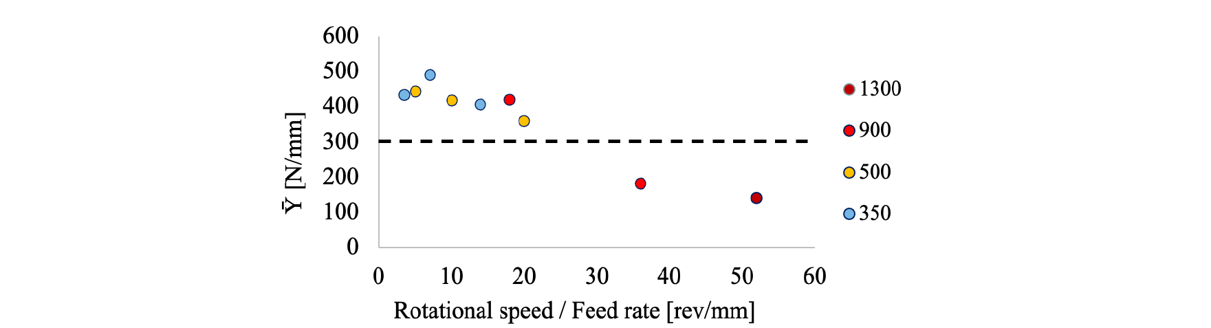
Fig. 4. Joints shear tests failure load vs. rotation/feed rate ratio
It can be asserted that good mechanical properties can be obtained when “cold” welding conditions, i.e. low values of the ratio between tool rotation and feed rate, are considered. On the contrary, high heat input does not result in proper bonding conditions between the sheets due to the different chemical-physical characteristics of the materials. As reported by Jacome et al. [6], the formation of intermetallic compounds (IMC) is enhanced by higher temperatures, resulting in both lower failure loads and lower ductility of the joints.
Fig. 5 shows the correlation between elongation at break, process parameters and joint failure load. It can be seen that "hotter" welds (resulting from a large value of the ratio between tool rotation and feed rate), besides showing smaller failure loads, are also characterized by lower ductility. This is consistent with the hypothesis on the effect of temperature on IMC’s made based on the findings of Jacome et al. [6].
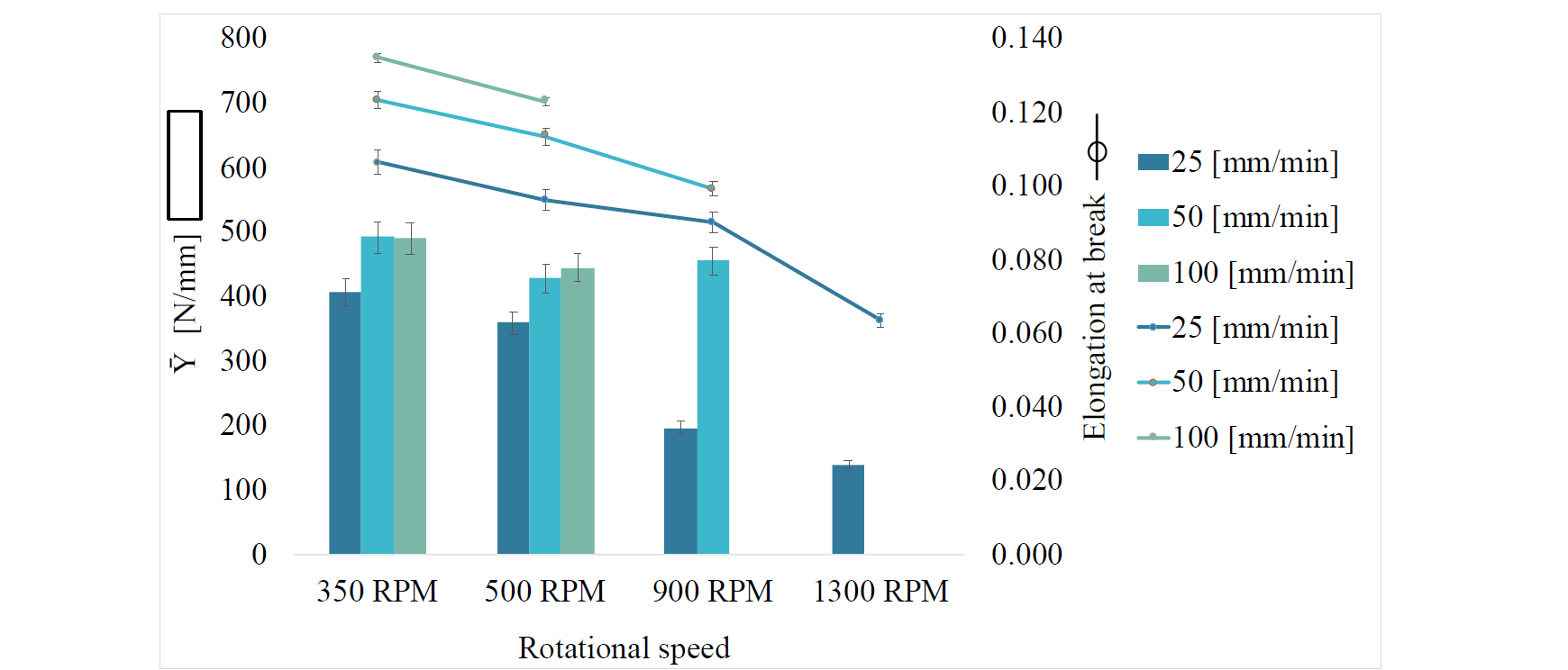
Fig. 5. Trend of deformations and of the load/length ratio of the joint
The analysis of micro-hardness was carried out. As it can be seen in Fig. 6, peaks are found at the interface between the two materials, with values which are again consistent with the formation of intermetallic compounds, as also demonstrated in a study performed by Wan and Huang [18]. The hardness values of the base materials correspond to, 150HV for the DH36 steel while 93 HV for the AA5083 aluminum alloy. It is observed that the hardness of the aluminum plate along the measurement line passing by the weld center does not change significantly along thickness, even close to the interface with steel. This is due to the approach selected consisting in a combination of tool pin height and tool plunge that allows the bottom of the tool pin to be, during the welding process, very close to the top surface of the steel plate without touching it. On the other hand, an increase in the hardness of the steel is observed close to the interface. As previously noted, this is due to the contamination with aluminum resulting in the formation of intermetallic [18]. The HV values reach a maximum at a distance of about 0.5 mm from the interface and decrease to the parent material levels at a distance of about 1 mm.
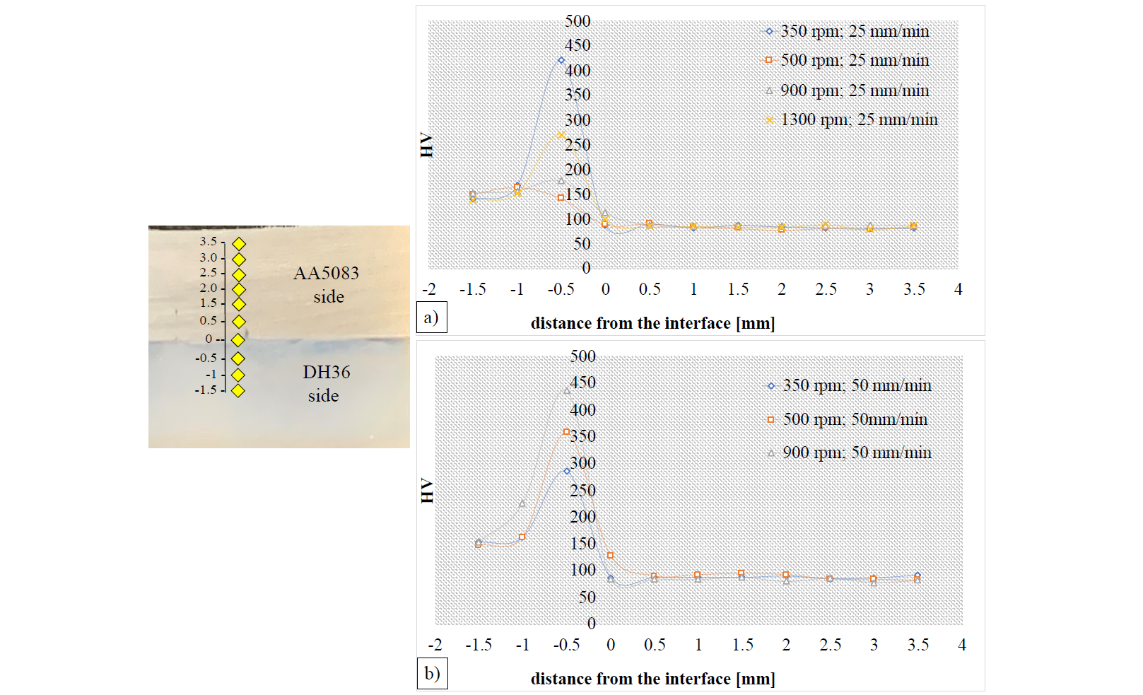
Fig. 6. Hardness trend for the cases study with fixed feed rate, equal to
(a) 25 mm/min and (b) 50 mm/min varying the rotational speeds
4 Conclusion
A workability window for LAP joint configuration between AA5083 and DH36, characterized by rotations that varied between 350 and 1300 rpm and feeds that varied from 25 to 100 mm / min was determined in the experimental campaign carried out. In addition to the perfectly obtained joints, this study also reports joints that showed defects, characterized by the site of defect onset, that are, internal to the weld bead (tunnel defects) and surface defects. In both cases, the defects were of a macro size and therefore visible to naked eye.
Mechanical characterization was also performed on the samples by subjecting them to shear and micro-hardness tests. for the case of shear tests, it could be asserted that good mechanical properties can be obtained when “cold” welding conditions (due to a lower revolutionary pitch) are considered. On the contrary, high heat input did not result in proper bonding conditions between the sheets due to the different chemical-physical characteristics of the materials.
For the case of micro hardness, the values of the base materials correspond to, 150HV for the DH36 steel while 75 HV for the AA5083 aluminium alloy but peaks are found near the interface between the two materials, with values consistent with the formation of intermetallic compounds. Further analysis is needed in order to quantitatively evaluate the position and thickness of the IMCs as a function of the process parameters.
