1 Introduction
A Blind Rivet Nut (BRN) is a mechanical fastener developed to equip plate material with a threaded part. Comparable to an ordinary pop-rivet, the BRN highly deforms during the installation process thereby clinching the fastener to the plate material. Dedicated installation tools are needed to deform a part of the BRN in such a way that a counter bulge is formed, shown in Fig. 1 (a). The plate is clamped between the head of the BRN and the formed bulb, realizing a mechanical connection. Borowiecki et. al. [1] investigated the structural strength of BRN joints in aluminium train equipment structure using both numerical and experimental tools. Because the main interest was on the structure itself, BRN joints were modelled as equivalent connectors. A similar simplified BRN model is also investigated by Klasztorny et. al. [2] using composite shell segments. The installation of a BRN is accompanied by high contact pressures leading to stress concentrations near the edge of the plate material. This initial stress state is not taking into account by the simplified BRN models. Hassanifard et. al. [3] simulated the setting process of the BRN in aluminium plate material to obtain the residual stress at the hole edge after setting the BRN. The stress state was accounted to evaluate the fatigue response of axially loaded BRN joints utilizing Smith-Watson-Topper damage models. Installing a BRN in CFRP laminate, the stress concentrations might cause damage of different natures (matrix cracking, delamination, fiber failure, micro-buckling). It is generally assumed that the induced stress and possible accompanied damage have a detrimental effect on the mechanical properties of the connection. A strategy to cope with the local degradation is modifying the conventional BRN design in such a way that the installing process causes minimal damage and the mechanical properties of the laminate remain unaffected. The latter strategy is experimentally demonstrated by Ueda et. al. [4] proposing a modified self-pierce rivet (SPR) to mechanically fasten CFRP laminates. Overviewing the difficulties using SPR in lightweight materials, Jäckel et. al. [5] also concluded that a reduction of damage can be advantageous when using SPR in CFRP. To arrive at such a redesign of the BRN, a profound understanding of the installation process and the complex stress state in the laminate requires dedicated research. FE techniques are a convenient method to gain a better understanding of the parameters that influence the forming behavior and the stress distribution in the plate material. To calculate a correct stress state in each ply of the laminate, a full 3D model is mandatory. Indeed, a carbon fiber weave and even more unidirectional fibers show orthotropic behavior which cannot be ignored. However, simulating the BRN installation process involves large plastic strains and high contact pressure leading to an excessive computational effort.
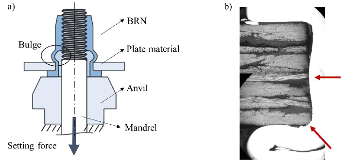 Fig. 1. (a) Schematic cross-section of BRN setting process, (b) Cross-section of BRN in CFRP.
In this paper, a strategy is presented to reduce the simulation time significantly by splitting the full 3D problem into two separate models. First, an axisymmetric model is used to efficiently simulate the BRN installing process and thus the forming process of the metal. The axisymmetric strategy provides an elegant solution to avoid a computationally heavy calculation scheme. However, the axisymmetric model implies isotropic material properties, therefore a second model is required to cope with the orthotropic nature of the CFRP plies. In the second model, the plies are modeled using 3D brick elements and orthotropic elastic material properties. Consequently, the movement of the axisymmetric contact nodes is mapped on the 3D plate model. To assess the potential error associated with the simplification of the laminate properties in the axisymmetric part, the results of the mapping strategy are compared with the full 3D model. Since the focus is on the stress state in the different layers of the laminate to estimate possible damage, the Tsai - Wu phenomenological failure criterion is used for comparison.
2 JOINT COMPONENTS
The mapping strategy is tested using a laminate composed of 8 5-harness satin weave (5HS) plies carbon (G0926 DK 1304 TCT), [45°, 0°]2s. HexFlow RTM6 Resin injection system is employed resulting in a total laminate thickness of 3 mm. The engineering constants and strengths of the ply prescribed by the manufacturer [6] are summarized in Table 1. The missing through-thickness stiffness and strength properties have been replaced by the cured neat resin properties. Considering the used lay-up and the limited difference in properties between the 0° and 90° orientation, the global in-plane properties of the laminate are quasi-isotropic. A standard available rivet nut, the M5 of stainless steel (SAE 304) is used for the present investigations. The rivets are installed using a setting force of 11.5 kN, the corresponding stroke is 3.9 mm.
To estimate possible deformation or damage after setting a rivet nut in the CFRP plate material, a polished cross-section of the joint is examined by microscopic images. Fig. 1 (b) shows the edge of the hole while the BRN is still in place. It can be seen that almost no damage is generated by setting the rivet in the selected CFRP. The red arrows indicate local compressive damage.
Table 1. Properties of G0926 DK 1304 TCT RTM6 ply.

3 FE MODELS BRN INSTALLATION
All simulations are performed using the LSDYNA SMP implicit solver with an automatically adjusted step time. LS-PrePost is used to define the necessary control card settings according to the recommendations of the keyword manual [7]. Because the installing process of the bulb is in essence a buckling calculation, the results are highly sensitive to the adopted geometry and material model. To accurately simulate the forming process of the bulb, the geometry (i.e. the diameter, thickness and length of the deformation chamber) is determined by precise measurement of the BRN’s cross-section. The material model of the BRN is calibrated using the efficient axisymmetric modeling approach, described in the subsection below. Next, the 3D model of the laminate is presented with the adopted axisymmetric and solid mapping strategy. Finally, the full 3D FE model of the installing process is discussed.
3.1 Axisymmetric forming simulation and material model
The BRN, the plate and both setting tools are included in the FE model as visualized in Fig. 2 (a). The geometry is meshed employing four node bilinear elements with hourglass controls. For each CFRP ply, the characteristic element size corresponds with 3 elements through the thickness, i.e. 0.125 mm. For the BRN, the characteristic element size corresponds with 18 element through the thickness of the deformation chamber, i.e. 0.04 mm. Throughout the forming simulation, the large deformation demands a high fidelity mesh. Strongly deformed elements will have a poor aspect ratio decreasing the solution’s accuracy. The numerical error is tackled using the available r-adaptive remeshing algorithm. A least-squares approximation processes a completely new mesh initialized from the old at different steps during the forming process. The adaptive meshing is only activated on the BRN with a frequency of 20 equally spaced time intervals during computation. Plus, the merging option for self-contacting materials is excluded.

Fig. 2. Axisymmetric model, (a) schematic overview, (b) resulting stress state in the laminate
The automatic surface to surface contact definition, dedicated to the implicit solution technique is used between the BRN, the laminate and the tools. Automatic single surface contact defined on the BRN avoids self-penetration. A static and dynamic friction coefficient of 0.15 is used between the part sets [8]. To cope with the buckling instability during the installation process, the setting forces is applied in two steps. First a displacement of 3.5 mm is defined on the rigid mandrel. Next, when the bulge is almost completely formed, the mandrel is loaded with the final setting force of 11.5 kN.
The used laminate has a symmetric and balanced lay-up, therefore the in-plane stiffness is quasi isotropic. Hence, the laminate material is assumed isotropic elastic with a Young’s modulus of 60 MPa, i.e. the average in-plane compressive stiffness. The strain hardening behavior of the BRN is identified performing tensile testes on the BRN. Fig. 3 (a) shows the experimentally obtained hardening curves. The tensile test only provided the plastic behavior up to 0.3 plastic strain. Setting the rivet induces much higher deformation, equivalent plastic strain values of about 2 are found at the center of the forming zone. An efficient method to define the post-necking hardening behavior of the BRN is by fitting a suitable hardening law to the experimental data and subsequent extrapolation [9]. The calibrated strain hardening curve is implemented using an elastoplastic material model (MAT_24). Strain rate effects are ignored in accordance with the performed quasi-static experiments. The material model is validated using the mandrel force as a function of the mandrel displacement, i.e. the so called setting curve. Fig. 3 (b) shows the experimental setting curve together with the setting curve obtained with the axisymmetric forming simulation (AXI SIM – M5 ev. Swift extrapol). It can be inferred that the experimentally measured setting curve is accurately reproduced by the axisymmetric model. The anvil and mandrel are assumed to be rigid. The resulting shape after spring back can be seen in Fig. 2 (b).
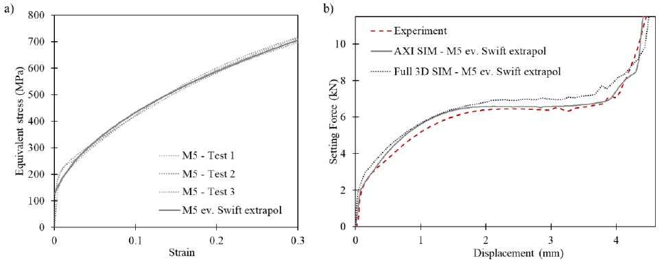
Fig. 3. M5 UPO 50 experimental obtained stress – strain curves of stainless steel 304 (a) and corresponding setting curve (b)
3.2 3D laminate and mapping strategy
The laminate 3D model is generated in LS-PrePost by revolving the axisymmetric mesh around the central axis in 180 segments. The resulting 216000 brick elements were assigned to eight different parts, representing the eight reinforced plies. The resulting mesh can be seen in Fig. 4 (a). The parts are bounded using a tie constraint enabling to simulate interlaminar stresses and possible failure. Where the axisymmetric model supposes isotropic material behavior, the 3D model of the laminate respects the orthotropic nature of the plies. The material is modeled orthotropic elastic in agreement with the properties of Table 1. To
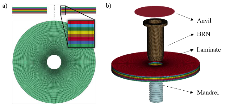 Fig. 4 (a) Mesh of the 3D laminate model, (b) full 3D model exploded view
To calculate the stress state in the 3D laminate model, the deformation of the axisymmetric plate model is transferred to the 3D model of the plate by scripting. For each axisymmetric contact node (black dots on the laminate shown in Fig. 2 (a)) two curves are generated representing the z and r displacement as a function of the simulation time. The two curves are mapped on the corresponding 3D contact nodes in terms of X, Y and Z boundary displacement. Running the displacement-driven 3D model, the stress state in the plate can be visualized. Because of the detailed modeling approach i.e. three elements through the thickness, the 3D model has as considerable amount of elements. Nevertheless, since there is no high deformation nor plasticity involved, the linear 3D laminate calculations finish fast.
3.3 Full 3D model
The full 3D model of the BRN has been obtained by revolving the 2D geometry around the central axis. Simplifying the helicoidal shape of the thread improved meshability and contact between the BRN and mandrel. Identical contact and non-linear solver settings are used for the axisymmetric and the 3D model. Again, r-adaptive meshing is defined to improve accuracy by avoiding a harmful element aspect ratio caused by excessive deformation. As the used 3D r-adaptive remeshing does not supports brick elements, the BRN is divided in 544000 constant stress tetrahedrons with nodal pressure averaging for bulk forming. The minimum and maximum edge length are in the range of 0.12 and 0.15 mm. The 3D laminate model used for the mapping strategy is imported into the full 3D model. Tools are meshed with rigid tetrahedron elements. In total, the model has 429710 nodes combined by 858265 elements. Fig. 4 (b) shows the different parts. The simulation of the BRN installation process suffers from large deformation and high contact forces making the full 3D approach time consuming. Comparing the setting curve of the axisymmetric and the full 3D model (Fig. 3 (b)), it can be seen that the global response is very similar. Differences are attributed to the different element formulations as the solid tetrahedron responds stiffer compared to the axisymmetric quadrilateral.
4 STRESS STATE IN CFRP LAMINATE
Since the in-plane compressive stiffness of the laminate is quasi isotropic, the simulated deformation will give an accurate prediction of the stretching of the hole diameter. On the other hand, the normal compression stiffness is mainly determined by the matrix behavior and deviates significantly from the in-plane values (3.2 GPa). Using the axisymmetric model, the deformation through the thickness of the laminate caused by the compressive force of the BRN is highly underestimated. In an attempt to quantify the error associated with the presented mapping methodology, comparison is made with the full 3D model. Near the BRN, a complex stress state is present. Consequently, the influence of the stress through the thickness relative to the in-plane stress can only be assessed using a damage criterion. Since the purpose of the damage model is to analyze the difference between the mapping strategy and the full 3D model, the phenomenological Tsai - Wu failure criterion is used. The authors are well aware that the Tsai-Wu failure criterion is not the most accurate damage criterion for compression in weave but it is deemed sufficiently accurate considering the limited observed matrix damage. Moreover, the simplicity of a single equation makes this approach attractive compared to complex degradation models.
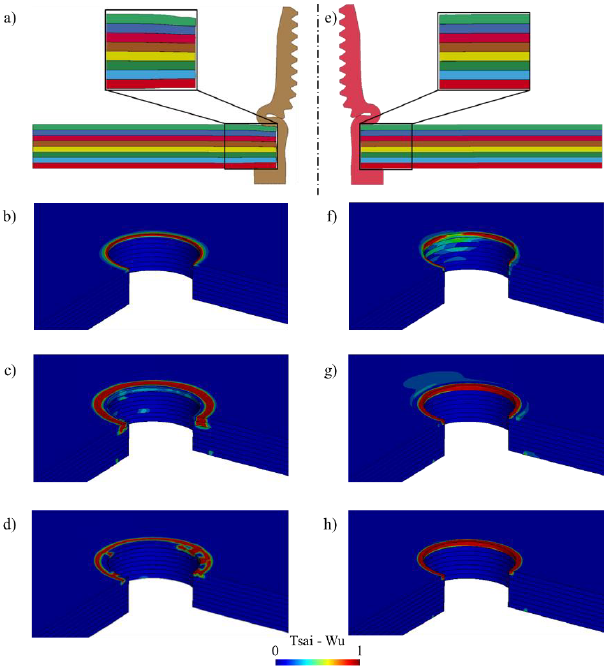 Fig. 5. Deformation of the laminate at maximum setting force using the full 3D model (a) and the resulting damage prediction at 1.3 mm stroke (b), at maximum setting force (c) and after spring-back (d) combined with the results of the mapping strategy for the same conditions as full 3D (e), (f), (g), (h)
Fig. 5 (a) and (b) show the deformation of the different layers when a setting force of 11.5 kN is applied. The difference in stiffness through the thickness is clearly visualized. The radial deformation on the other hand is very similar. For the sake of completeness it must be noted that by using the force controlled simulation, a slightly different stroke is obtained. The difference is mainly caused by the stiffness of the plate and can also be seen in Fig. 3 (b). To clarify the error caused by the underestimation of compressive deformation, Tsai-Wu’s single equation is fringed at different steps during the installation process. The first state is at the beginning of the buckling process, at a stroke of 1.3 mm (Fig. 5 (b) and (f)). At this point a radial force on the edge of the hole is most dominant and damages the edge according to the employed damage criterion. At the maximum setting force of 11.5 kN the damage accumulates more for the full 3D simulation (Fig. 5 (c)) compared with the mapping strategy (Fig. 5 (g)). The difference between the two results indicates that the stress through the thickness has a significant influence when using the damage criterion. Further analysis of the stress state clearly showed that the radial stress in the two plies closest to the formed bulb is remarkably higher in comparison to the other plies. Moreover, focusing on the full 3D model, no additional damage is expected near the edge. A hydrostatic stress state on the edge of the hole reduces the calculated damage parameter. Using the mapping strategy, the in-plane compression remains most dominant. Therefore, only near edge damage is expected. After spring back, the stress through the thickness drops and the in-plane components become more dominant. For the full 3D model (Fig. 5 (d)) again damage is expected on the edge but only at the 0° and 90° orientations of the fabric. Focusing on the result of the mapping strategy after spring back (Fig. 5 (h), it can be seen that the critical zone remains the same.
Overviewing the different steps of the setting process, the results of the mapping strategy indicate that the deformation through thickness has a considerable difference. The detrimental effect of the compressive force on the plies close to the bulb cannot be ignored if a detailed prediction of the induced damage is demanded. Therefore the full 3D model is deemed to be most accurate, particularly, if combined with a dedicated damage model. Nevertheless, the enormous reduction of calculation time (factor 20) makes the present mapping strategy attractive to check the location of the critical zones in quasi-damage free situations. Moreover, the approach is excellent for an extensive sensitivity analysis to arrive at an optimized design. Additionally, plate material with less difference between in - plane and through thickness stiffness, for example fiberglass reinforced plastics, will significantly extend the methods potential.
5 Conclusion
In the present paper, a numerical framework is demonstrated enabling to simulate the stress state in CFRP laminate during and after BRN installation. The methodology consist out of two successive FE models. An efficient axisymmetric model to simulate the installation process of the BRN suffering from high deformation and contact pressure and an accurate 3D model of the laminate. The deformation of the axisymmetric laminate model is subsequently mapped on the second FE model. The aim of the strategy is to replace a complex full 3D model to simulate the installation process of the BRN. The latter is thoroughly discussed and successfully applied. Compared to the full 3D model, the results of the mapping strategy indicate that the deformation through the thickness is underestimated. Estimating the influence of the error relative to the other stress components, Tsai - Wu’s single equation shows a considerable difference in the compressive force on the plies close to the bulb. Nevertheless, the enormous reduction of calculation time (factor 20) makes the approach attractive to check the location of the critical zones or to perform a sensitivity analysis. Comparing the predicted damage zone with the experimental cross – section, for both simulation strategies good agreement can be seen.
Further work will embark on a more dedicated damage criterion. The M5 BRN induces moderate damage enabling to simplify and use only elastic properties without a progressive failure criterion. Using larger BRNs will induce a much higher stress state in the laminate increasing the need for a degradation type of model instead of a pure elastic model .
Acknowledgements
The authors would like to thank Dejond NV for providing the BRNs used in this study. In addition, the support of LSTC in providing developers versions of the FE code is gratefully acknowledged by the authors.
