1 Introduction
In the last decades, the trend in metal cutting has moved towards more sustainable processes. Flood cooling and lubricating with conventional metalworking fluids (MWFs) has been substituted with dry or near-dry cutting approaches [1]. However, some hard to machine materials have poor thermal conductivity and require the use of additional cooling liquids such as cryogenic fluids to remove the heat generated in the cutting zone. The two most commonly used cryogenic fluids in machining are liquid nitrogen (LN) and liquid carbon dioxide (LCO2). Due to poor lubricating ability of cryogenic media it is often necessary to use the additional oil to lower cutting forces, tool wear and consequently improve surface finish [2, 3]. A recent approach is the combination of LCO2 and oil, delivered via minimum quantity lubrication (MQL). Compared to LN being liquid at T = −196 °C, LCO2 is stored at room temperature and a pressure of p = 50 bar and delivered to the cutting zone in a stable liquid state, reaching T = −78,5 °C after expansion at the room pressure [4]. Recent development in this field enables single-channel supply of pre-mixed LCO2 and MQL into the cutting zone showing promising results in reducing tool wear, improving surface finish and lowering cutting forces [5].
In addition to different cooling and lubrication approaches, the machining process can be further improved by the use of tools protected with a hard coating. In dry cutting, the cutting edge of the tool is exposed to high temperatures (1000 °C and above) and stresses in the cutting zone [6, 7]. Hence, a hard coating with high hardness, thermal stability and oxidation resistance is required to improve the tool life. Nanocomposite and nanolayered hard coatings exhibit superior properties, including hardness, thermal stability and oxidation resistance [8]. Both nanolayered and nanocomposite quaternary TiAlSiN hard coating was found to have prominent hardness (3240 HV) [8, 9].
In this paper we present a comparison between machining martensitic stainless steel under different cooling and lubrication conditions (dry, flood, LCO2, LCO2 + MQL) using tools with a TiAlSiN hard coating. The influence of these conditions on tool wear, surface integrity and cutting temperature was investigated.
2 Experimental setup
Experimental milling was performed on a workpiece made of 1.2083 (AISI 420, X40Cr14) martensitic stainless steel with high chromium content, used for plastic moulds. The workpiece material, used for this study was hardened and three times tempered, reaching the final hardness of 55 HRc. The upper surface was pre-shaped to the machining contour, shown in Fig. 1, with a stretched length of L = 170 mm. A curve with an inclination of 0° to 45° allowed uniform wear of the cutting edge of the mill. The direction of milling was alternating down-milling and up-milling.
Fig. 1. a) Machining setup (cross-section of the machining contour in inset); b) Position of thermocouples
Cemented carbide (WC-Co, hardness 1840HV30) 2-flute ball end mill with the diameter of 8 mm, was coated with TiAlSiN PVD coating by magnetron sputtering in a standard industrial unit CC800/9 (CemeCon) from two pairs of TiSi and TiAl segmental targets. Lip angle of the cutting tools (δ) was 75° ± 1° and average radius of the cutting edge of coated tools was 12.8 µm ± 2.0 µm. Milling was performed on the vertical machining CNC center Doosan NX 6500 II.
Experiments consisted of four cases, each related to different cooling/lubrication conditions: dry machining (dry, minimal blowing of air to remove chips), flood cooling (emulsion, Blaser B-Cool 9665, 5%), cryogenic machining (straight LCO2 at pressure p = 57 bar and a flow rate of ~200 g/min) and the combination of cryogenic + MQL machining (LCO2 + oil). For LCO2 + MQL assisted machining, a special MQL oil Rhenus SSB (viscosity 3.5 mm2/s at 20 °C) was used, delivered at a flow rate of 200 g/h. Straight LCO2 and combination of LCO2 + MQL were delivered through single-channel system (ArcLub One) [5, 10] at the LCO2 mass flow rate found as optimal for cooling [11] and typical MQL flow rate for oil. The nozzle (d = 1 mm) for LCO2 and LCO2+MQL delivery was oriented to the cutting zone, at an angle of approx. 60° to the tool axis (Fig. 1). Machining parameters were fixed; the axial depth of cut ap = 0.4 mm, the radial depth of cut ae = 0.4 mm, the cutting speed vc = 188 m/min, and feed rate fz = 0.1 mm/tooth. The tool overhang was constant at l = 25.0 mm and controlled after every tool change. At constant cutting parameters and the total length of one pass amounted to 97,000 mm, the milling time was approx. 80 min.
2.1 Tool flank wear measurements
Progression of flank wear (VB) was documented in regular intervals (after every milling pass) considering the expected tool life from preliminary experiments under dry conditions, until critical wear for fine machining (VBmax = 0.2 mm) on flank face was reached. Therefore, for every measurement, the carbide end mill was removed from the tool holder and examined under Keyence VHX-6000 incident light microscope under 50× and 100× magnification. After completion of each measurement the tool was inserted back to the tool holder, the overhang was controlled to achieve reliable and repeatable machining conditions. Due to different tool wear rates, each experiment was terminated based on individual findings.
2.2 Temperature in the cutting zone
In the dry, LCO2 assisted and LCO2 + MQL assisted machining, the temperature just below the workpiece surface was measured for the first milling pass with a new tool. Therefore, for each machining condition two horizontal holes (d = 0.6 mm with a depth of 10.0 mm) were drilled using electrical discharge machining (EDM) just below the horizontal surface of the workpiece with a distance between the workpiece surface and the edge of the hole of ap + 0.10 mm ± 0.03 mm. The offset of holes allowed the end mill not to damage thermocouples during the machining. Positions of the holes were at the starting point and at the end point of the machining, so the temperature was measured with a new, unused tool and with a semi-worn tool after the first pass. K-type thermocouples were embedded in the workpiece and connected to National Instrument CompactDAQ NI 9213 analog digital converter and computer with a software for data acquisition.
2.3 Surface roughness measurements
After milling the workpiece, surface roughness measurements were performed on the top horizontal surface of the workpiece (surface inclination 0°, Fig. 1 b)) at distance 0 mm (beginning), 110 mm (middle) and 220 mm (end) from the starting point in the direction of machining. Surface roughness was measured using a Mitutoyo Surftest SJ-301 roughness measurement device. Measurements were repeated twice in order to minimize any measurement error caused by the operator.
3 Results and discussions
3.1 Tool wear
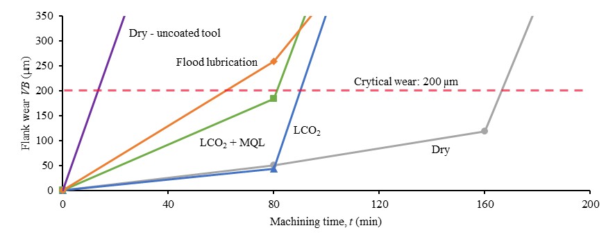
A comparison of the tool life for four machining strategies is illustrated in Fig. 2. As a reference, the same type of uncoated tool was used under dry machining conditions with the same cutting parameters. As anticipated, the uncoated milling tool flank face already exceeded the wear criterion after one pass (machining time t = 80 min), measurement of VB value was not possible due to completely worn cutting edge.

Fig. 2. Flank wear VB for different cooling/lubricating conditions over tool life time
Dry machining resulted in the longest tool life, exceeding the critical wear during the third machining pass, followed by the LCO2-assisted machining with comparable rapid initial and steady state wear rate. Unexpectedly, the addition of oil (MQL) to LCO2 further increased the wear rate, resulting in a shorter tool life time. Flood cooling assisted machining led to critical wear during the first machining pass. Typically, LCO2 + MQL assisted machining results in tool wear reduction [3, 11] but, surprisingly, in this study the assistance of LCO2 and LCO2 + MQL cooling/lubricating liquids negatively affected the tool life. Although the wear measurement interval is relatively large, this does not affect the determination of the tool life, as the differences between individual strategies are clearly identifiable.
Furthermore, analysis of flank face, presented in Fig. 3, showed similar wear types for all four machining strategies. However, crater wear was also observed during machining with emulsion assistance. Visible change in the color of the hard coating in the area along the worn edge confirms the wear of the top layer of the coating. No visible workpiece material was observed adhering onto the coated tool surface, regardless of the cooling/lubricating machining conditions.
Fig. 3. Wear on flank face after the first pass (t = 80 min) for a) dry, b) flood assisted, c) LCO2 assisted and d) LCO2 + MQL assisted machining
3.2 Surface roughness measurements
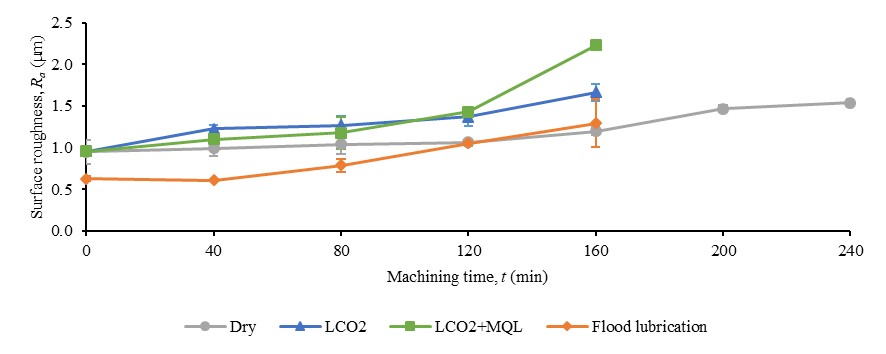
The machined surface roughness parameters Ra were measured for all four machining strategies, the results are presented in Fig. 4. Surface roughness of dry machined workpiece is stable over the entire machining time with a slight increase in the rapid tool wear phase reaching the maximum Ra value of 1.59 µm. Surprisingly, compared to dry machining, assistance of LCO2 has a markedly negative effect on the surface quality. Adding a small quantity of oil via MQL slightly reduces the Ra values in the break- in and steady-state tool wear stages compared to straight LCO2 machining, while the Ra value increases markedly after the onset of rapid wear rate. This could be attributed to lower friction coefficient [12] due to the lubricating effect of oil. However, exceeding the critical wear limit, the surface roughness increases rapidly. In contrast, the flood lubrication assisted machining resulted in the lowest average surface roughness, even when the tool wear was already above the critical limit.

Fig. 4. Surface roughness for different cooling/lubricating conditions over tool life time
Moreover, the negligible roughness difference between LCO2 and LCO2 + MQL cooling/lubricating conditions indicates insufficient lubrication in the LCO2 + MQL mode. Similar behavior of the LCO2 + MQL assisted cutting strategy was also reported by other studies [13, 14]. The poor performance and consequently shorter tool life time of the LCO2 + MQL machining strategy could be attributed to incompatibility of the MQL oil and the workpiece material. However, the oil used in this experiment was specially developed to be mixed with LCO2 and used for the LCO2 + MQL assisted machining [13]. As reported by [15], it noticeably reduces the tool wear and surface roughness compared to flood cooling using the same flow rates and delivery methods as used in this study when machining 42CrMo4 steel.
3.3 Temperature in the cutting zone
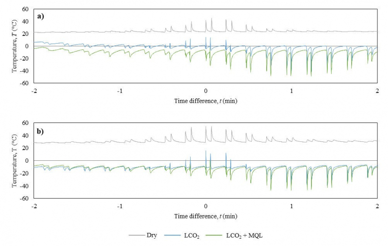
A comparison of the temperature range just below the workpiece surface achieved during machining is shown in Fig. 5 where the time difference on the X-axis represents relative time difference with respect to the transition point of the tool just above the thermocouple. The highest measured temperatures for each thermocouple position in each machining strategy refer to the temperature at the moment when the cutting zone position was just above the thermocouple measuring point while the lowest measured temperatures were reached slightly afterwards. This could be attributed to external delivery of cooling/lubricating liquid or the position of the nozzle and the delivery direction.
Fig. 5. Comparison of cutting temperatures for dry, LCO2 and LCO2 + MQL assisted machining in thermocouple positions a) at start and b) at the end of the first machining pass
In dry machining, the workpiece material was in thermal equilibrium with the ambient temperature. No additional coolants were used during the process, so all the generated heat was dissipated to the chips, tool and workpiece. The shape of temperature peaks on the temperature-time chart follows the principle of a sudden heating and a gradual cooling after machining. From the measured temperatures it is also noticeable that the tool wear causes the temperature to rise slightly. Indeed, this could be explained with wear related increase of the cutting force during machining as reported by [14] and [16].
With assistance of LCO2, the temperatures at the beginning of the test, when the cutting tool was new, were noticeably lowered. Although, compared to dry machining, higher machining forces were found when using straight LCO2 cooling strategy [16, 17], which increases heat generation in the cutting zone. Lower peak-to-average temperature ratio indicates the cooling effect of LCO2. At the end of the first pass, when machining with a semi-worn tool, higher temperatures would be expected compared to the beginning. Higher peak-to-average temperature ratio confirms occurrence of higher machining forces while lower temperatures seemed to be achieved with pre-cooled workpiece affected by the chosen LCO2 delivery method and thermal capacitance of the workpiece material.
Furthermore, addition of oil to LCO2 significantly improves the cooling capability of LCO2, being able to achieve lower temperatures. Considering a peak-to-average temperature ratio compared to straight LCO2, the results demonstrate a slight improvement of the lubricating ability. Similar findings were reported in the study [18], where addition of MQL oil to LCO2 vastly reduced the coefficient of friction compared to straight LCO2.
Even though the use of LCO2 and LCO2 + MQL cooling/lubricating methods lowered the temperature in the cutting zone, both strategies resulted in an increased tool wear rate and surface roughness compared to dry machining. The reason for such phenomena is most likely in hardening of the workpiece material with the transformation of retained austenite to martensite caused by cryogenic cooling. Indeed, the used method of coolant/lubricant delivery had an effect on a larger area along the workpiece. In addition, generated toolpath performs several cryogenic thermal treatments on the workpiece material before the actual cutting. This is in agreement with studies [19] and [20], where hardening of the material up to 400 µm beneath the cryogenic assisted machining surface was observed. The LCO2 + MQL combination with improved cooling capability induced a higher hardness compared to LCO2, which is also consistent with the findings in this study.
4 Conclusion
In this study, four different cooling/lubricating conditions were tested for end-milling of martensitic steel 1.2083 with TiAlSiN PVD coated carbide ball mill using the same machining parameters. Tool flank wear, surface hardness and temperature just under the cutting zone were obtained. The TiAlSiN coated tool vastly outperformed the uncoated tool under dry machining conditions, exhibiting a roughly three times longer tool life. When comparing dry and LCO2 assisted machining, opposing results can be observed, where lower temperatures led to increased roughness and shorter tool life. Moreover, the addition of MQL oil to LCO2 resulted in a lower surface roughness, while also decreased the temperature in the cutting zone and unexpectedly reduced the tool life. Neither LCO2 nor LCO2 + MQL were able to improve the surface roughness values, achieved by flood cooling machining strategy. Cooling/lubrication method with emulsion was found to have the shortest tool life of all four selected machining strategies with coated tools. However, further research on the impact of cryogenic treatment on 1.2083 stainless steel hardening effect has to be done. Ultimately, dry machining is suggested to be used for end milling of 1.2083 steel, using a tool with the TiAlSiN hard coating.
Acknowledgements
The authors acknowledge the financial support from the Slovenian Research Agency (program "Young scientists" and research core funding No. P2-0082)


