1 Introduction
Stainless Steels are Fe-C alloys with more than 11% of Cr. In this family alloys, Austenitic and duplex stainless steels are considered be the best in corrosion resistance. Among the austenitic steels, the AISI 304 grade is very used for its low corrosion and high mechanical properties. However, when it is needed better mechanical properties (tensile and yield strength), not neglecting high corrosion resistance, duplex stainless steels are a good alternative. The development reported in the construction sector indicates emerging applications of duplex stainless steels in structural design. In this sense, the machining study of this materials is an important issue, in order to better understand the performance of the tools and the quality of the parts manufactured for highdemand industries, such as, food processing, chemicals shipping vessels, oil and gas extraction platforms. [1-4].
Austenitic steels are formed by γ-austenite phases, which is responsible for ductility and resistance to uniform corrosion; Duplex stainless steel consist of equal amounts of α-ferrite and γ-austenite phases and combines the inherent benefits of both phases. The α-ferrite phase contains a body-centred cubic crystal structure. This phase in duplex is responsible for the excellent pitting and crevice corrosion resistance properties. The γ-austenite phase, a face centered cubic microstructure promotes the superior strength and toughness [1].
Stainless steels are often considered as poorly machinable materials, leads to the rapid wear and tool failure. Indeed, Stainless steels are considered as difficult to machine materials due to their tendency to work hardening, their toughness and relatively low conductivity. The high fracture toughness increases the temperatures in the interface of tool/chip, leading to poor surface finish, poor chip breaking and built-up-edge (BUE) formation, even at elevated cutting speeds [2]. In addition to the preceding properties, stainless steels have high alloy content, which form abrasive carbide phases that leads to faster tool wear.
Stainless steels are difficult-to be drilled, particularly without high pressure through the spindle and drill, because of their high ductility. Coolant must blow out new chips from drilled holes, sliding the chips on the rake faces of the tool flutes. The highpressure system improves not only the cooling rate and transportation but also the chip breakage [5].
Drills with three cutting edges are reported in the literature as being capable of drilling holes with better circularity, eccentricity, straightness and cylindricity than ordinary drills with two cutting edges. In the three-flute drill, the whirling vibration frequency associated with two-flute drills disappears [6], and thereby rifling marks do not result on the hole surface. This is partly explained by its geometry, the chisel edges of the ordinary drills are formed by the intersection of two adjacent flank surfaces, giving it the approximate shape of a line. On the other hand, drills with three cutting edges have a star-shaped chisel edge due to the intersection of three flank surfaces. Indeed, the star-shaped chisel edge converges at one point, making these drills more stable [7]. However, drills with three cutting edges are shown to be more sensitive to cutting parameters, while drills with two cutting edges withstand more severe conditions [8].
2 Experimental details
2.1 Test materials
In order to evaluate the effect of work material on the performance of the drills, two distinct alloys of stainless steels, AISI 304 and Duplex GX6CrNiN26-7 (EN 1.4347), were selected as the workpiece material. The chemical composition and relevant mechanical properties were given in Table 1 and Table 2.
The workpieces were prepared in dimensions of 120x70x70 mm3 and 300x100x40 mm3 for stainless steel 304 and duplex, respectively. The samples were firmly secured in a vise during drill operation.
Table 1. Chemical composition in weight percentage.
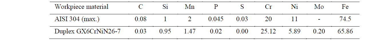
Table 2. Mechanical properties of tested materials.
|
Mechanical property |
AISI 304 |
Duplex GX6CrNiN26-7 |
|
Tensile strength [MPa] Yield strength [MPa] Elongation [%] Hardness [HB] |
510 – 620 205 – 310 45 – 60 211 – 214 |
686 456 25 277 |
2.2 Equipment and experimental procedure
The experiments were carried out in a Haas UMC-750 SS five-axis machining center, equipped with external low-pressure (2-4 bar) and internal high-pressure (21 bar) cooling system. The oil-based coolant was diluted in water, to get a concentration of 8% or higher. A 10 mm carbide drill with three cutting edges and internal cooling channels, manufactured by Palbit®, was used to drill holes with a depth of 30 mm (3xD) in a single pass and a 15 mm spacing between them. Same machining parameters were selected for all tests, cutting speed of 50 m/min (n=1592 rpm) and feed rate of 105 mm/min.
To examine the wear of the tool was used a digital microscope Dino-Lite Basic integrated with image acquisition software Dino Capture 2.0, without realizing the drill from the tool holder. The measurements were then carried out via software Axion Vision LE.
A Mitutoyo SJ-201 surface roughness tester was used to measure the surface roughness of machined holes in two opposite positions, a total of six measurements were made, three in each position. Based on the ISO 4288 standard and the available space, a sampling length of 2.5 mm was used with an evaluation length of 7.5 mm.
The diameter of the holes was measured several times all the way around in order to find the maximum and minimum values. Measurements were made at 8 mm and 25 mm depth with a Bowers XTDU10-BT 3-point internal micrometer, with an accuracy of 0.003mm.
A piezoelectric triaxial accelerometer, model 356B08 manufactured by PCB Piezotronics, was glued to the CNC spindle according to the respective system axes. A data acquisition card, National Instruments NI 9234, was used to convert the analog signal to digital and then processed at a sample rate of 1613 Hz.
The machining performance is evaluated by observing the tool wear, surface roughness, enlargement in hole size and vibration analysis. Electrical discharge machining (EDM) by wire erosion was used for both materials to cut some holes up to total depth, in order to separate the hole into 2 parts and carry out a visual analysis of the hole surface. A total of four tests were carried out under different conditions, as shown in the Table 3.
Table 3. Conditions applied on tests and number of holes performed.
|
Tool |
Material |
Cooling Type |
Nº holes performed |
Test |
|
Twist drill of three cutting edges |
AISI 304 |
External |
3 |
A |
|
Internal |
60 |
B |
||
|
Duplex |
External |
30 |
C |
|
|
Internal |
60 |
D |
3 Results and discussion
3.1 Tool deterioration
The international standard ISO 8688-1 was used as a reference to characterize the type of deterioration that occurs in the drills and to determine the end of life of the tool. Despite ISO 8688-1 has been developed to face milling operations with carbide tools, with suitable modifications, this standard describes well the damage phenomenon of other types of tools and operations.
As recommended in the standard, the type of deterioration that to contribute most to the end of useful of tool life, was used as criterion. Thus, for test A and C was considered that the main damage observed was loss of tool fragments in random positions (non-uniform chipping - CH2). In this case was admitted a maximum chipping length of 0.4 mm. During test B and D, the main damage observed was a progressive development of constant flank wear by abrasion (uniform flank wear - VB1). While for test B was detected a small loss of tool fragment, as shown in Fig. 1 (test B), for test D any chipping was observed up to the end. Once for test B and D, the flank wear stayed away from the criterion VB1 = 0.35 mm, it was decided to stop the test after 60 holes.
Fig. 1 shows for each test, the deterioration of cutting edge of the drill. The tool deterioration is mainly detected at chisel edge and flank edge. Moreover, the chipping tends to form near the chisel edge, where the effective cutting speed is lower and for that reason the chip's adhesion is higher.
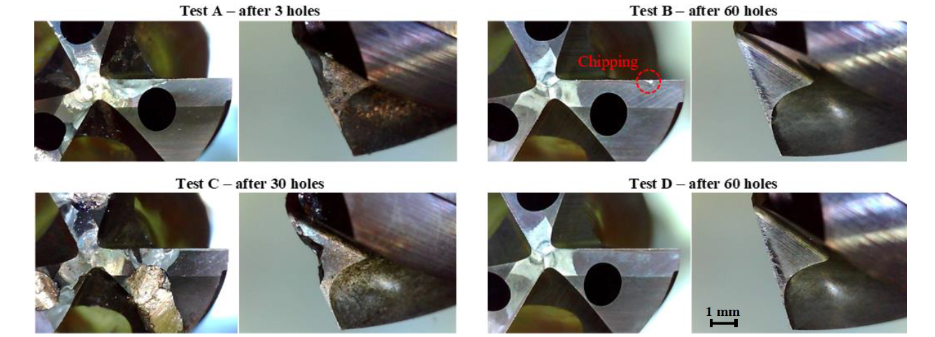
Fig. 1. Deterioration of cutting edge of the drill in different tests performed.
For all tests, the adhesion of the chip to the tool was observed. However, chip adhesion was more pronounced when external cooling was used and when it comes to AISI 304 stainless steel. For this reason, in test A it was only possible to drill 3 holes, where the built-up-edge is too evident (Fig. 2).

Fig. 2. Large built-up-edge that occurs in test A.
When internal cooling is used, the deterioration values tend to stabilize after the first holes, reaching a steady wear stage up to the hole number 60. On the other hand, when external cooling is used, the values tend to increase rapidly until the criterion is reached, as shown in Fig. 3.
The presence of built-up edge raise chipping to the flank surface. The high-pressure system improves not only the cooling rate and transportation but also the chip breakage. Once tensile strength and hardness of duplex stainless steel is higher, it is expected lower adhesion in this material, as effectively observed, extending the tool life. Once for any type of test material, the tool life is always lower for external cooling, leads to believe that type of cooling used has a greater influence on tool deterioration than the test material.
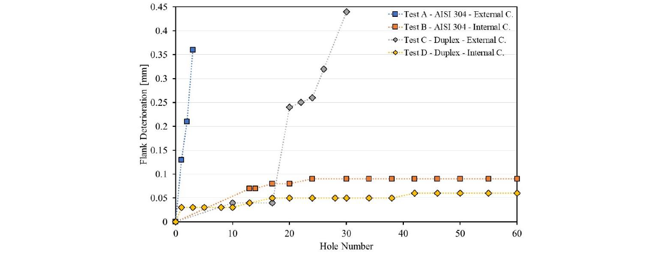
Fig. 3. Evolution of flank deterioration when drilling AISI 304 and duplex stainless steels.
3.2 Surface roughness
The Fig. 4 shows the roughness average (Ra) and the mean roughness depth (Rz) evaluated. The Ra and Rz values and the respective standard deviation are based on all holes performed for each sample. As would expect, for both materials, the higher roughness values are obtained for external cooling, since in this situation the chip length is higher, the extraction is less fluid with more random movement, causing greater roughness on the surface of the hole. Concerning to the materials, AISI 304 stainless steel, shows a worse performance, mainly due to lower hardness values.
Once for any type of cooling, the surface roughness is always lower for duplex stainless steel than AISI 304, leads to believe that test material used has a greater influence on the roughness than the cooling be internal or external. In opposite way, it was observed prior that the cooling be internal or external, has a greater impact on tool deterioration than test material used.
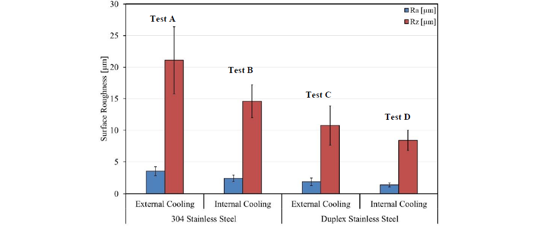 Fig. 4. Surface roughness of the holes for different tests.
3.3 Hole size
In order to determine the hole diameter, the diameter of the tool was evaluated before carrying out any drilling operation. For a drill with a nominal value of 10 mm, was observed that the tools diameter varied between 10.000 and 10.016 mm. All hole diameter was larger than tool diameter, because of the vibration, chatter, and drilling temperatures.
In test A the tool deterioration has evolved very fast, not allowing a significant sample of values to be taken, making it difficult to draw conclusions. However, there is a noticeable difference between the maximum and minimum diameter, indicating a larger out of roundness (ovalization) compared to other tests.
In tests B and D, in which internal cooling was used for different test materials, the maximum and minimum hole diameter values remain almost constant up to the end. In these tests, the drills practically did not wear out and the tools geometry remained constant. On the other hand, in test C, as the number of holes increase, the hole diameter tends to decrease. When comparing the graph of flank deterioration (Fig. 3 – test C) and diameter variation (Fig. 5 – test C) is possible to conclude that lower diameters registered are related to the faster deterioration of the tool, that occurs from hole number 17 to hole number 30.
It is possible to conclude that the stability of the drilled holes is more related to the maintenance of the tool in good conditions, than to the test material used.
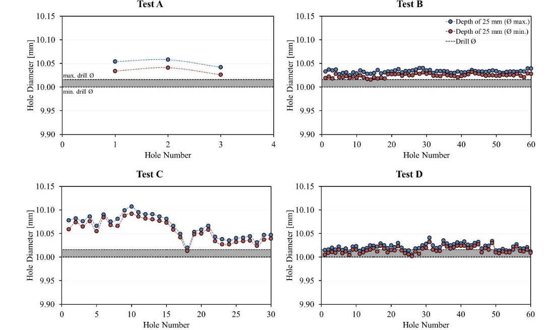
Fig. 5. Maximum and minimum diameter of the holes evaluated for different tests, at a depth of 25 mm.
Fig. 6 allows to conclude that the holes made on duplex stainless steels are straighter, once the difference in diameter between the top (evaluated at a depth of 8 mm) and bottom (evaluated at a depth of 25 mm) of the hole, is less than in AISI 304.
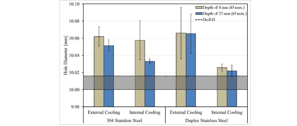
Fig. 6. Average diameter variation for different tests.
3.4 Vibration analysis
Vibration analysis in the time and frequency domain have been registered. For frequency domain, a Fast Fourier Transform (FFT) was applied and a number of prominent periodic frequency were observed. In this analysis, it is important to understand what phenomena each spike corresponds to. Although it is intended to identify the tool wear and failure in the drilling operation, cutting induced vibration and the movements of various parts of machine (rolling bearings, gears, belt drives, etc.) may be reflected with different amplitudes in the frequency graph.
As mentioned in other works [9], the phenomenon of cutting during drilling is expressed by the spindle frequency (fs) and tool meshing frequency (fm), whose frequencies correspond to the values calculated by the formulas 1 and 2 and observed in Fig. 7, where 𝑛 corresponds to the spindle speed and 𝑧 to the number of cutting tool teeth. It is also observed a spike at 159.2 Hz, which corresponds to the second harmonic frequency (f2h) of tool meshing (formula 3). Concerning to the spikes observed at 50Hz, this may be associated with the frequency of electrical noise, although other unidentified effects may overlap.

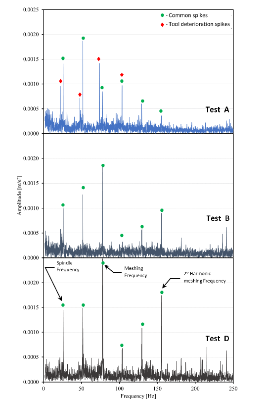
Fig. 7. Induced vibration in test A (hole number 3), test B (hole number 60) and test D (hole number 60) with different levels of deterioration.
The spikes observed at approximately 100 Hz and 130 Hz are common to test A, B and D and could be associated to movements of various parts of machine. The spikes of greater and lower intensity in tests B and D are the same. However, when spikes associated with the tool deterioration phenomenon appear (test A), the intensity of the spikes is not in the same order, since other phenomena are added and being registered simultaneously. Moreover, different phenomena may overlap, as shown in test A for 100 Hz. Vibration results are not displayed for test C because the registration was not successful.
In the case of the vibration recorded for hole number 60 of test B and D, no identified spike appears to be related to the deterioration of the tool, as in this case the tool has no appreciable deterioration. The waterfall graph for test D (Fig. 8) shows that during all performed holes of this test, the vibration signal has no significant changes, once spikes are always at the same frequencies, with no new spikes, but their intensity increases, probably associated with uniform flank wear observed. On the other hand, in the case of test A, in addition to the spikes already mentioned (common spikes), new spikes are observed, which are attributed to the strong deterioration of the tool that occurs in hole number 3 (non-uniform chipping). The increase in deterioration will cause a disturbance of the already existing spikes, resulting in an increased amplitude of the sidebands, that is proportional to the damage [10,11]. The sidebands tend to appear near the fundamental frequencies. A considerable increase in these frequencies suggests that the drill geometry is changing.
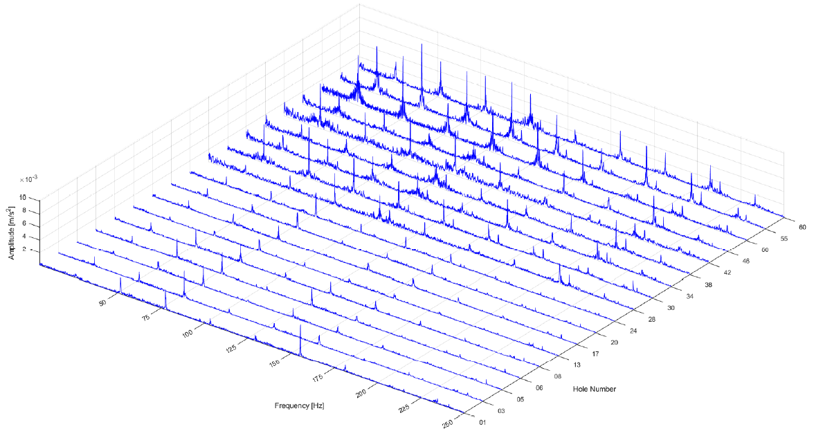
Fig. 8. Waterfall graph of induced vibration for performed holes on test D.
4 Conclusion
After carrying out this experimentation work, it was possible to obtain several conclusions about drill cutting performance of austenitic and duplex stainless steels, when are applied three cutting edges drills. Concerning to the tool life, it was possible to conclude that the most important factor to increase the number of holes made is the use of high-pressure internal cooling. When external cooling is used, AISI 304 have a worse behaviour than duplex stainless steel, due to greater susceptibility to built-up-edge formation and work hardening. The tool deterioration is mainly non-uniform chipping for external cooling and flank wear for internal cooling.
For any type of cooling, the surface roughness is always lower for duplex stainless steel than AISI 304, showing that the surface roughness is more related with the material used. A larger out of roundness (ovalization) of the hole happens when the tool is in the worst condition and the holes made on duplex stainless steels are straighter than for AISI 304.
The vibration analysis with Fast Fourier Transform is an effective method to identify and quantify various phenomena related with drilling operation and tool life.
Acknowledgements
The authors would like to thank Palbit, Hard Tools Solutions Company (www.palbit.pt) by technical support, tools and stock materials supply and GENE HAAS Foundation by the scholarship granted.
