1 Introduction
Nickel-chromium based superalloys, and in particular Inconel 718, are widely used in high temperature and extremely corrosive environments, such as jet engines parts, gas turbine components, and rocket motors in the aerospace industry, due to their ability to maintain proper mechanical characteristics also in extreme conditions [1]. The retain of these properties, combined with low thermal conductivity, high chemical affinity with cutting tool materials, and the presence of abrasive carbide particles, makes Inconel 718 a difficult-to-cut material, and it brings to a very pronounced tool wear [2,3]. The amount of tool wear heavily affects machining forces, cutting efficiency, residual stresses and surface roughness of the machined product, and the tool life itself [4-6]. Moreover, when drilling is considered, due to its internal machining nature and to the higher difficulty of the chip to be removed from the cutting zone, stronger mechanical and thermal loads on tool and workpiece are generated if compared with external machining (turning and milling) [7], making the tool wear control more prominent. The evolution of tool wear can be assessed by means of several experimental tests, but these are expensive and time consuming [8]. To overcome this costly approach, Finite Element Methods (FEM) can be utilized. The capability of FEM to predict cutting forces, torques, and surface integrity as a function of process parameters and tool geometry for different machining operations has been demonstrated by numerous research [7-9]. The limits of the commercial software for Finite Element Analysis (FEA) are related to the impossibility of updating the geometry of the worn tool, and consequently the effects of it on forces and workpiece quality are not foreseeable [10]. In order to surmount this lack, in this work, a self-released subroutine able to modify the tool geometry in DEFORM 3D simulations by considering the volume reduction of the tool is presented. The validation of the model has been performed by the comparison of simulation results with the experimental data obtained by drilling tests of Inconel 718 with conventional metal working fluids (MWF) lubrication [11]. The resulting simulated worn tool geometry, in agreement with the real tool geometry, has been used to perform FEM drilling simulations and to predict how torque changes as a function of the tool wear. The good comparison between simulated and experimental values demonstrated that, in a predictive maintenance perspective, the model can be profitably implemented to optimize the tools replacement.
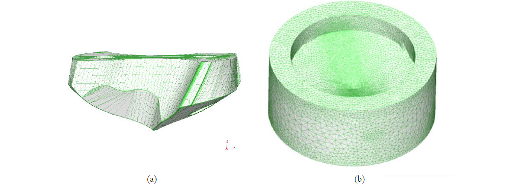
Fig. 1. The 3D CAD geometry of the tool (a) and the workpiece (b).
2 FE simulations of tool wear
2.1 FE drilling model
The three dimensional CAD geometries of tool and workpiece are illustrated in Figure 1. The helicoidal drill design (Figure 1a) must comply with the actual tool shape. The workpiece (Figure 1b) is modeled as a cylinder with a hole which replicates the profile of the drill. In DEFORM-3D, the FEM modelling of the chip formation is based on the chip separation criterion [12]. The fracture criterion defines a variable and a critical value of breakage. The contact between the tool cutting edge and the workpiece determines a crack in an element of the mesh if the variable reaches the critical value. Tools can be modeled as a rigid body while workpieces visco-plastic behavior can be defined as flow stress dependent on strain, strain rate and temperature. The software allows to select the fracture criterion between various models [13]. They include the Cockcroft-Latham criterion, which is defined by the Equation 1.

where 𝜀𝑓̅ is the effective strain; 𝜎1 is the maximum principal stress; D is a material constant. The thermal proprieties of the workpiece, the tool and the coating materials were defined in terms of thermal conductivity, heat capacity, emissivity and thermal expansion. The relative movement between tool and workpiece is achieved by assigning a feed speed and a rotation speed to the tool. The workpiece is fixed by adding a constrain to the nodes of mesh which belongs to the external side surface of the cylinder. FEM simulation of drilling requires the definition of the friction between tool and workpiece. Several researchers adopted shear model in machining [14, 15], which is defined by Equation 2.

where 𝜏𝑓 is the tangential stress, k is the shear yield stress and m is the shear friction factor. It must be determined through tribological test or it can be assumed by literature. The FEM analysis considers also the heat exchange between objects. The simulator requires the heat conduction coefficient hcond across the tool-workpiece interface and the convection coefficient hconv to perform the thermal simulation. In machining, a high value of hcond is usually used to reach steady state in a short time [16]. Furthermore, hconv strongly depends on the cutting fluid proprieties and temperature and it can be experimentally determined.
2.2 Tool wear modeling
The simulation of tool flank wear (VB) is performed by using a subroutine written in Fortran language [10]. It iteratively calculates the incremental wear (ΔVB) and subsequently it reconstructs the worn tool flank. The procedure includes a preliminary Lagrangian simulation to reach the thermo-mechanical steady state. At the beginning of the chip formation mechanism, the contact area with the tool surface increases. The increasing is limited by the chip curvature. It determines the separation between chip and the rake surface of the drill.

Fig. 2. The scheme of the tool wear on flank as function of distance from the drill center (a) and a typical trend of VB in time [17] (b)
The mechanical steady state is guaranteed only if the tool-chip contact area is constant, while the thermal steady state is ensured by a constant temperature of the cutting edge nodes. The steady state of drilling constitutes the starting point for the wear calculation. The modification of the tool flank geometry depends on time and on the distance r between the drill center and each mesh node which belongs to the cutting edge. Several researches demonstrated as usually the flank wear linearly increases from the chisel edge to the begin of the curved part of the cutting edge (r<rl). Furthermore, the flank of wear remains constant (VBMAX) along the curved part until the drill periphery (r≥ rl). A schematization of the worn profile is shown in Figure 2a. One of the achievements of this work is to demonstrate the validity of this morphology of the worn tool also by comparing the geometrical model outlined with others.
About the time, the duration of the drilling must be discretized in interval of time (Δt). The subroutine calculates the tool wear increment along the curved part of the cutting edge (ΔVBMAX) with a periodicity of Δt. The code requires the experimental tool wear rate (dW(t)/dt) to correctly update the cutting edge geometry for each time instant. Figure 2b shows a typical trend of the flank wear as a function of the time. The trend was identified in several researches [17, 18] and it can be divided into three stages. The first region is characterized by an accelerated wear, while in the second region the wear linearly depends on time. In the third and last stage, the wear rate increases drastically until the end of the tool life. Once the tool wear rate is known, it can be used to calculate ΔVBMAX for the i-th iteration through Equation 3:

Once the ΔVBMAX is known, it can be used to calculate the width of the wear on flank along the entire cutting edge. Different computation strategy can be adopted in order to calculate different morphology of the worn flank. The procedure to update the tool mesh as function of VB(r)i is the most critical part of the subroutine. The mesh nodes which belongs to the flank, the rake and the cutting edge must be identified in order to calculate the local rake angle (γ) and the local clearance angle (α). As the wear VB, also γ and α depends on the distance r. The subroutine calculates the angles with the purpose to compute a local wear volume (LWV) in correspondence of each node of the cutting edge [10]. Since the LWV depends on the local VB, α and γ, the FEM is capable to compute the actual loss of volume due to wear on flank. Finally, the subroutine deletes all the nodes contained in the LWV. A new tool geometry is extrapolated by the updated mesh and it is used for the further iteration.
3 Study case
An experimental study case was used to test the reliability of the procedure. In particular, the study case was designed with the purpose to simulate different profile of wear on flank and to compare them with the experimental profile. The drilling tests were performed by Chen and Liao [11] with a multi-layer TiAlN PVD coated tungsten carbide drills manufactured by Guhring. Table 1 summarizes the geometrical features of the drill. The tests consist in pecked-drilling of Inconel 718 samples with a constant cutting speed equal to 13.2 m/min and a constant feed rate equal to 40 mm/min. Metal working fluid (MWF) was employed to lubricate and to evacuate the chip. During the drilling, the torque and the thrust force were acquired by using a Kistler 9273 dynamometer.
Table 1. Geometrical features of the drill.
|
Diameter [mm] |
10.5 |
Point angle [°] |
140 |
|
Chisel edge angle [°] |
48 |
Back taper angle [°] |
5 |
|
Margin width [mm] |
0.26 |
Web thickness [mm] |
0.53 |
|
Edge radius [µm] |
40 |
Helix angle [°] |
35 |
An optical microscope and a scanning electronics microscope (SEM) were utilized to inspect the tool wear condition. The SEM images allowed to evidence the development of micro-cracks distributing along the chipping area. The propagation of the cracks determined a progressive damage of the cutting edge. A crater wear was formed on the tool rake and the flank wear gradually increases. Finally, the wear rate increases drastically until the end of the tool life. Figure 3a shows the worn flank after 600 seconds of machining. The width of the wear lip was periodically measured on the curved section of the cutting edge, where it was maximum (VBMAX). The trend of VBMAX is illustrated in Figure 3b. For the first ten minutes, the wear rate was constant, and it was equal to 4.4·10-4 mm/s. At the end of the drilling tests, the wear rate increased to 1.2·10-4 mm/s.
The drilling tests were simulated with the FEM model described in section 2. The tool was modeled as a rigid body and meshed with 200k tetrahedral elements, setting a maximum size of 0.3 mm. The elements with minimum size were located around the cutting edge and the ratio between minimum size and maximum size was set equal to ten. The multi-layer TiAlN PVD coating was added. The workpiece was meshed with more than 100k elements with a size ranging from 0.05 to 0.5 mm. The thermo-viscoplastic behavior of Inconel 718 was selected from the DEFORM database, such as the proprieties of the materials which constitutes the tool [10]. Table 2 summarizes the critical value D of the Cockcroft-Latham criterion. The table expresses also the shear friction factor m and the convention coefficient hconv of the lubricant. The first was determined through tribological tests [10], while the second was calculated by Outeiro et al. [7].
Table 2. Critical value, friction factor and convention coefficient
|
D |
500 |
|
m |
0.1 |
|
hconv |
0.930 KW/m2K |
The subroutine was utilized each 45 s to generate a worn geometry of the drill. The experimental wear rate was replicated, included the acceleration after 10 minutes of machining. Three different profile of wear on flank along the cutting edge were tested. The first model utilized the increment ΔVBMAX to calculate the flank wear on the curved part of the cutting edge, where the width of wear profile is considered constant. Along the linear section of the cutting edge, the actual increment of wear is lower. Equation 4 allows to calculate the wear VB(r)i at the i-th iteration.
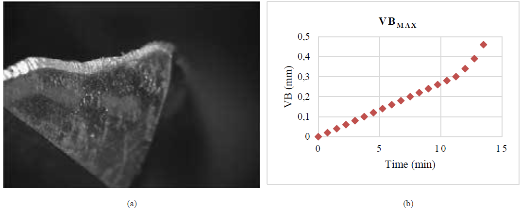
Fig. 3. The wear on tool flank after 10 minutes (a) and the trend of VBMAX (b)

A second geometrical model of tool wear provides a constant wear along the curved part of cutting edge with a discontinuity located where the cutting edge becomes linear. It is expressed by Equation 5 and it depends also on the diameter of the drill (D)

The third model was based on the hypothesis of linearity along the entire cutting-edge profile. The Equation 6 allows to calculate the wear VB(r)i at the i-th iteration.

4 Results and discussion
The thermo-mechanical steady-state was reached after a drill rotation equal to 180°. The temperature of the tool cutting edge and the torque rapidly increase during the first 45°. Subsequently the torque reaches an equilibrium point at 10.7 Nm. The cutting edge temperature reached a peak of 320 °C in the correspondence of the most stressed nodes. Figure 4 compares the tool wear predictions after 675 s, developed with the models explained in section 3. The time corresponds to a width of the wear on flank equal to 0.3 mm. According to ISO standards, it is considered a limit for the tool life. The profile elaborated by the subroutine based on Equation 4 does not provide any discontinuity along the cutting edge. As expected, the subroutine provides a constant wear on flank with a width of 0.3 mm in the curved section, as visible in Figure 4a. The second subroutine utilized Equation 5 and it computes a point of discontinuity where the curvature of the cutting edge change (Figure 4b). The linear section results less worn as compared with the first FE prediction. Finally, an other continuous geometry was designed by the code implemented on Equation 6. Moreover, the wear increases as the distance from the drill center increases also along the curved section of the cutting edge as a consequence of the cutting speed increasement (Figure 4c). The actual tool [11], visible in Figure 3a, shows a good correspondence with the geometry showed in Figure 4a. The curved section of the cutting edge compensates the increasing of the cutting speed avoiding an undesired increase of the stress. The first model was utilized to simulate the evolution of the wear with a period of 45s. The progression of the wear is compatible with the experimental evidences and in particular with the VB trend shown in Figure 3b. The computational time to elaborate each step is lower than 500 s. The elevated computational rate can be considered adequate to integrate the subroutine in a commercial FE software.

Fig. 4. A comparison of the different wear flank profile after 675 s. The constant wear on curved cutting edge (a), the discontinuity wear on the point of curvature change (b) and the linear wear profile (c).

Fig. 5. The torque dependence on the flank wear (a), the contact point on flank after 360 s (b) and after 675 s (c).
The new geometries were utilized to perform Lagrangian simulations to investigate the wear effect on drilling of Inconel 718. The Figure 5a shows the comparison between experimental e FE prediction about torque. Generally, the FEM seems to overestimate the torque. A possible explanation is an overestimation of the friction coefficient in the FEM model. Furthermore, the torque increasement as the wear increases was correctly simulated. This trend is determined by the increasement of the contact zone along the tertiary shear zone which determines an increasement of the cutting force. The contacts between workpiece and flank after 360 s is visible in Figure 5b, while the contacts after 675 s is visible in Figure 5c.
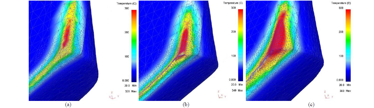
Fig. 6. The temperature distribution on the tool surface in steady state condition on the new tool (a); after 360 s (b); after 675 s (c).
The model can predict also the increment of the tool temperature determined by tool wear. Fig. 6 shows the cutting edge, the flank and the face of one cutting flute in different wear conditions. The increment of the red-colored high temperature zone around the tool corner is well visible. The maximum value of temperature progressively increased from 320 °C to 349 °C after 360 s (Fig.6a and Fig.6b). The tool heating becomes faster for larger tool wear and the temperature reaches an absolute maximum of 393 °C. Also the tool face and flank temperature is affected by tool wear.
5 Conclusion
In this paper, the development and application of a self-released subroutine, in DEFORM-3D FE simulation software, capable to modify the tool geometry as a function of the volume reduction due to wear has been presented. Its validation has been performed by the comparison of the worn tool geometry simulation results with the experimental data of drilling tests of Inconel 718, in terms of drilling torque evolution. The good agreement between simulations and experimental tests demonstrated the effectiveness of the presented subroutine and, in a predictive maintenance perspective, its suitable implementation in the tool replacement optimization phase.
