1 Introduction
Martensitic stainless steel has been widely used for applications including injection molds and dies, dental and surgical instruments due to the high strength with the good corrosion resistance. This grade of steel is suitable to hardening after heat treatments of quenching and tempering. After hardening, the material properties include high strength, toughness, and corrosion resistance [1]. In terms of machining, however, Stainless steels are one of the difficult-cut metals due to the high strength, the high rate of work hardening, and the low thermal conductivity [2]. Tamimi and Hossainy measured the cutting force, specific cutting energy, shear angle, friction coefficient on the rake face, the shear stress on the shear plane, the shear strain in turning of AISI 420 of 260 HV hardness at various cutting speeds, feed rates, and the rake angles. The cutting force decreases in low cutting speed due to build-up-edge [3]. The cutting force and the power consumption in turning of AISI 420 stainless steel were predicted with finite element method [2]. The result shows the effect of cutting speed on power consumption is less than the cutting depth effect due to small cutting forces at high cutting speeds. Tsai et al. applied ultrasonic vibration to milling of STAVAX (modified AISI 420) stainless steel. The surface finish was improved with an end mill at a large helix angle in an optimum amplitude of the ultrasonic vibration[4].
As an effective manufacturing of functional parts with complex geometries and low volumes, the additive process has recently been applied to high value materials such as stainless steels, maraging steel, cobalt chromium alloys, titanium alloys, and Inconel in several industries [5][6]. Several manners have been developed, as selective laser melting (SLM), selective laser sintering (SLS), electron beam melting (EBM), laser engineered net shaping (LENS), and direct metal deposition (DMD) [6][7][8][9]. For instance, an optimal design of a cooling channels system in an injection mold has a possibility to achieve high production rates with high product qualities [10]. Zhao et al. fabricated an injection mold insert of AISI 420 with complex cooling channels with SLM, and the hardness increased at a high laser power for phase composition [11]. Krakhmalev, et.al investigated in situ microstructural evolution in AISI 420 stainless steel during SLM. The hardnesses in upper and inner regions were measured 750 HV and 500-550, respectively[5].
Regarding surface integrity of the metallic additive manufacturing (AM) products, additive/subtractive hybrid manufacturing was taken to control surface roughness and accuracy [12]. The subtractive process in the hybrid AM is economical in terms of the removal material volume and the tool wear [13]. Montevecchi et al. compared the cutting forces in milling of AISI H13 steels processed in LENS and wire-arc additive manufacturing (WAAM). The tangential and the radial cutting coefficients on WAAM material becomes higher and lower than in the LENS one, respectively [14]. Heigel et al. [12] discussed residual stress of AISI 17- 4 stainless steel fabricated into cylindrical geometry in a hybrid AM. The process promotes compressive stresses on the inside surface and tensile stresses on the outside one of the cylinder. After AM process, the compressive stress, in turn, appears on the outside by finishing with an endmill. Allegri et al. [15] reported hardness on the machined surface increases with the feed per tooth in micro milling of medical CoCrMo alloys made by SLM. The. The cutting process of Ti-5553 fabricated in SLM was compared with the original Ti-5553 [16].
The paper investigates machinability of AISI 420 stainless fabricated by SLM steel in milling process. The cutting force and chip morphology of workpiece fabricated in SLM are compared to wrought workpiece in the cutting tests. An analytical model, then, is applied to discuss the difference in the cutting models.
2 Cutting test
2.1 Workpiece
The workpieces of AISI 420 stainless steel fabricated SLM (SLM workpiece) were prepared for the cutting tests in LPBF process on an AM machine (Sodic OPM250L). AISI 420 powder supplied by Sodic Co. Ltd was melted with a Yb-fiber laser. A wrought martensitic stainless steel (STAVAX modified AISI 420) was employed as a reference (wrought workpiece). Both metallographic structures of workpieces are shown in Fig 1, where the polished surfaces were etched by a reagent of picric acid, hydrochloric acid, and Ethanol. Circular arc boundaries of melt pool are observed in SLM workpiece, as shown in Fig. 1(a). The Vickers hardness (HV1 JIS Z2244 2009) of workpieces are shown in Fig. 2. The SLM workpiece was approximately 2.5 times larger than the wrought one.
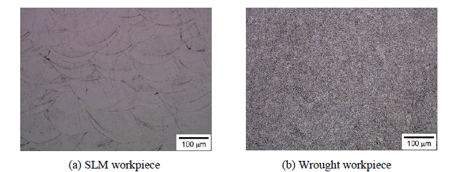
Fig. 1 Metallographic of workpiece
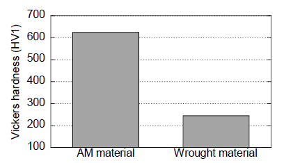
Fig. 2 Hardness of workpiece
2.2 Cutting test to measure cutting force
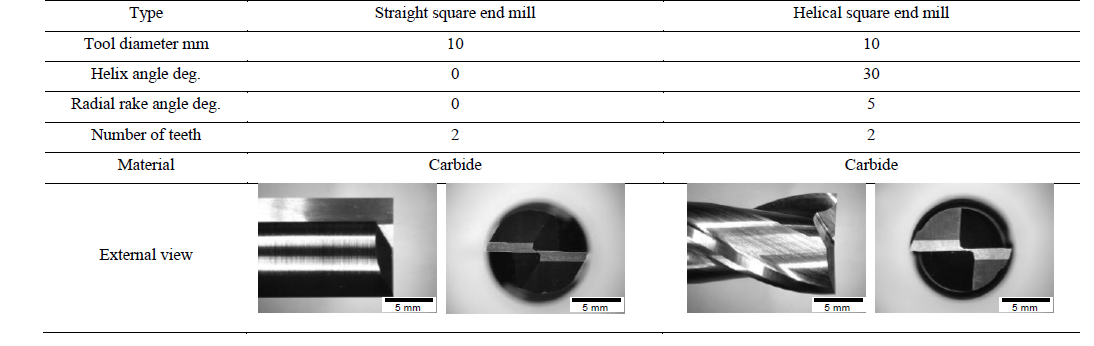
The cutting tests were conducted in a 3-axis machining center (FANUC ROBODRILL α-T14iF), as illustrated in Fig. 3. The workpieces embedded in a phenolic resin were clamped on a piezoelectric dynamometer (KISTLER 9272) mounted on the machine table. The end mills were clamped to the spindle of the machine tool with the tool shank interface. Reference surfaces were finished to control the axial and radial depth of cut before cutting tests. The down-cut milling was performed in one tool path along -X direction in Fig. 3 in an axial and a radial depth of cuts of 1 and 0.2 mm, respectively, where the spindle speeds were 637 and 1592 min-1 (cutting speed of 20 and 50 m/min), and the feed rates were 0.05 and 0.1 mm/tooth, as shown in Table 1. The chip morphologies were observed with an optical microscope (KEYENCE VHX6000). In order to investigate the effect of tool geometry on the machinability, straight and helical square end mills shown in Table 2 were employed for the cutting tests.

Fig. 3 Cutting force measurement system
Table 1 Cutting conditions
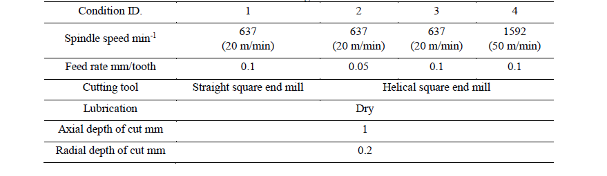
Table 2 Tool geometry
3 Machinability of SLM AISI 420
3.1 Cutting force measurement
Figure 4 shows the cutting force loaded on the workpiece at a spindle speed of 637 min-1 and a feed rate of 0.1 mm/tooth. Since the workpiece is machined with the 2-flute end mill, the cutting force changes periodically in 0.047 sec cycle which is a half of a cutter rotation. The cutting force in down-cut milling rapidly raises at the edge engagement, then, decreases according to the uncut chip thickness. The large cutting force and vibration appear in milling of SLM workpiece with a straight end mill in Fig. 4(a). On the other hand, the cutting force changes without vibration in milling of wrought workpiece. Regarding the effect of tool geometry on the cutting force, in milling with the helical end mill, the cutting force reduces with vibration because the helical edges engage gradually from the bottom to top of the tool. The large helix angle should be taken to reduce tool failure induced by the tool vibration. It is notes that the cutting forces of SLM workpiece in Fig. 4(a) and (c) were similar to those of wrought workpiece in Fig. 4(b) and (d), even though the SLM workpiece is much harder than wrought workpiece. Figure 5 compares the average cutting force at the edge engagement of both workpieces as:
(1) Little difference appears in the cutting force of SLM workpiece compared to the wrought workpiece in the same cutting conditions.
(2) The cutting force becomes small at a high cutting speed when comparing the results of Condition 3 with Condition 4.
(3) Z component of SLM workpiece indicates the larger negative value in comparison to the wrought workpiece in Conditions 3 and 4.
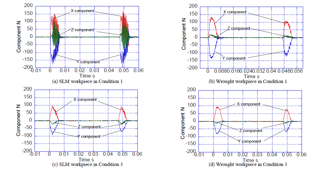
Fig. 4 Cutting force measurement

Fig. 5 Cutting force at edge engagement
3.2 Chip morphology
Figure 6 shows the chip morphologies after milling of SLM and wrought workpieces at Conditions 1 and 3. The thin and discontinuous chip is observed in milling of SLM workpiece, as shown in Figs. 6(a) and (c), because the SLM workpiece has hardened and brittle properties due to quenching at high temperatures in a laser melting. Especially, in milling with the straight end mill, a large vibration is induced because the large shear may occur simultaneously on the straight edge. Meanwhile, although a discontinuous chip is observed in milling of SLM workpiece with the helical end mill, the vibration in the cutting force becomes small because the large shear may occur sequentially on the helical edge. In contrast, the thick and continuous chips are observed in milling of the wrought workpiece, as shown in Figs. 6(b) and (d), due to the ductility of annealed workpiece. Assuming that the chip flows toward the radial direction of the tool in milling with the straight end mill, the shear angle at edge engagement is estimated by:

where t1, tc, and α are the uncut chip thickness, the chip thickness, and the radial rake angle, respectively.
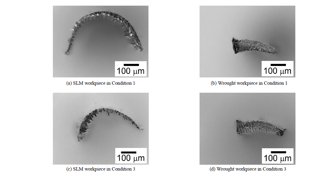
Fig. 6 Chip morphology
According to the chip thickness measured at the edge engagement and the maximum uncut chip thickness calculated geometrically, the shear angles of SLM and wrought workpieces are estimated 34 and 19 deg in Condition 1, respectively. Therefore, the length of the shear plane and the shear stress on the shear plane of SLM workpiece are approximately 55 % and 1.8 times with respect to those of the wrought workpiece though the cutting forces of SLM workpiece are nearly equal to those of wrought workpiece.
4 Cutting Process in Milling of SLM AISI 420
4.1 Cutting force model based on minimum cutting energy
A force model is applied to predict the cutting force components with the chip flow angle. Three-dimensional chip flow in milling, as shown in Fig. 7, is interpreted as a piling up of the orthogonal cuttings in the planes containing the cutting velocities V
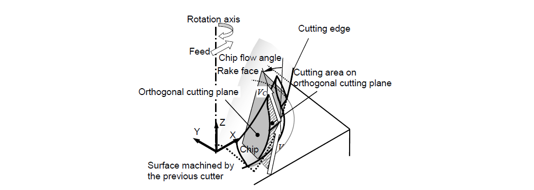
Fig. 7 Chip flow model in analysis
and the chip flow velocities Vc. Although plastic deformation actually occurs in the chip formation, the interaction between each orthogonal cutting plane is ignored on the assumption that a rigid chip flows at an angular velocity. The orthogonal cutting models are given by the following equation:

where 𝜙, τs and β are the shear angle, the shear stress on the shear plane and the friction angle. V and t1 and α are the rake angle, the cutting velocity and the uncut chip thickness in the orthogonal cutting. Aij (i = 0,1,2; j=0,1,2,3) are parameters acquired in the orthogonal cutting tests. The data can also be identified or refined with referring to the actual cutting force in milling by the inverse analysis [17]. The cutting force should be regarded as the sum of the indentation force component due to the ploughing and the chip generation force component due to shearing in the shear zone and friction on the rake face. For the sake of simplicity, this study employs the orthogonal cutting data expressed as Eq. (2) on the assumption that the chip generation force component is the major effect here, where the indentation force component is implicitly associated with the parameters for the uncut chip thickness. Regarding friction on the rake face, friction angle associated with friction coefficient is controlled by the third equation in Eq. (2). Because the orthogonal cutting data are acquired in the actual cutting tests for the combination of the tool and the workpiece materials, friction in the interface between the tool face and the chip is characterized in the actual cutting. The shear angle and the shear stress on the shear plane depend on the material behavior. The thermal effect on the material behavior may be mainly controlled by the first term related to cutting velocity dependency, which is associated with the cutting temperature.
4.2 Cutting force simulation
In the cutting tests, the orthogonal cutting data were acquired as:
SLM workpiece:

Wrought workpiece

Figure 8 compares the simulations and the measured cutting forces under Condition 3. The force model is verified in agreement of the simulated cutting forces with the measured ones.
4.3 Change in cutting model
Figure 9 shows the chip flow angle, the shear angle, and the friction angle at the center of the cutting depth, which are simulated with the cutting model. The changes in the uncut chip thickness are also shown in the figures. The chip flow angles are defined as the wedge angles between the projected directions of the tool axes on the rake faces and the chip flow directions. The chip, therefore, flows into the radial direction with increasing the chip flow angle. The chips of the SLM and the wrought workpiece flow at nearly the same directions. The shear angle of SLM workpiece becomes larger than that of wrought workpiece. Since the cutting force of SLM workpiece is almost equal to those of wrought workpiece, the shear angle and the shear stress on the shear plane is expected to be large. Although the shear stress on the shear plane slightly increases with uncut chip thickness. the average in milling of SLM workpiece in Fig. 9(a) is estimated as 1447 MPa, which is 1.86 times larger than 778 MPa of the wrought workpiece in Fig. 9(b). The friction angle goes up slightly as the cutting thickness decreases due to the relatively increase of edge roundness effect.
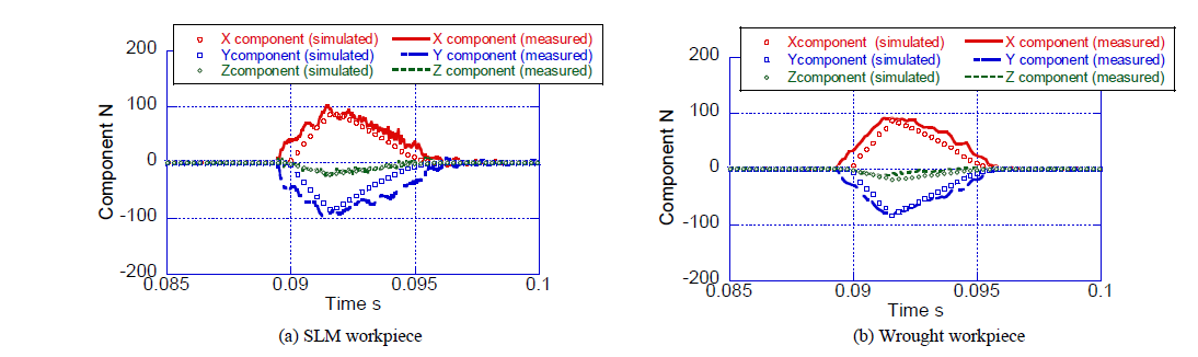
Fig. 8 Cutting force simulation in Condition 3
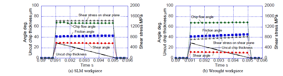
Fig. 9 Change in cutting model in Condition 3
5 Conclusion
Machinability of AISI 420 martensitic stainless steel fabricated SLM has been discussed in the cutting tests and the simulation. The force model based on the minimum cutting energy was applied to the simulation of milling.
The cutting force of SLM workpiece is nearly equal to that of wrought workpiece. The chip morphologies, however, are different between both workpieces. The large shear angle is expected in milling of SLM workpiece in comparison to the wrought workpiece. In the simulation, the shear angle of the SLM is larger than that of the wrought workpieces based on the orthogonal cutting data. The shear stress on the shear plane is estimated as 1447 MPa, which is 1.86 times larger than that of wrought workpiece. Although the shear stress on the shear plane is large in the SLM workpiece in comparison to the wrought workpiece, the result shows the cutting force does not become large significantly due to a large shear angle.
