1 Introduction
Material removal manufacturing processes are very present in industry and represent about 15% of world production. This shaping process is unavoidable and remains one of the main pillars for the manufacture of mechanical components. A lot of research has been carried out to optimize it and to increase the productivity while reducing costs. One of the key research topic is tool wear. Indeed, wear generates an increase in cutting forces, a rise in temperatures and a deterioration in the quality of the manufactured component. More and more, manufacturers have to meet severe specifications and tools are often discarded before their critical wear to secure for example the dimensional quality of the part. This tool changeover time is a significant cost for companies and generates a reduction in productivity.
Milling is a common operation but still specific considering its discontinuous nature. Several studies have shown the effects of this interrupted cutting on the temperature, on the machining forces but also on the tool degradation [1-3]. Repetitive impacts have been identified as the first factor leading to the milling tool wear. Several studies have shown that an increase in the number of impacts leads to an increase in flank wear [4], their frequency being obviously controlled by the cutting speed. These cyclic mechanical loadings often lead to the chipping or even collapse of the cutting edge and generate specific wear modes. An increase in cutting speed, but also cutter engagement, also generates more intense heating and increases the temperature delta between the maximum peak and the minimum peak. Whereas thermal modelling in milling is very present in the literature especially via analytical studies [5,6], very limited work can be found on the wear simulation.
The 15-5PH a martensitic stainless steel hardened by copper precipitation and specifically designed to achieve a high toughness, high resilience, and high resistance to fatigue. It can be seen as a hard to machine material with a strong adhesion tendency promoted by a high chromium content as soon as the temperatures are sufficiently elevated [7-10]. Despite the fact that it is a key material in aerospace industry, it has not really been studied and especially not in milling. Understanding the phenomena induced during this operation appears indeed more difficult than during a more conventional turning operation. Due to these specificities and the related knowledge gap, predicting the service life in milling of 15-5PH is even more a challenge.
The proposed work is thus a first attempt to study the physical phenomena occurring in milling of 15-5PH and to identify the related wear mode. First, a simplified test bench leading to a single tooth orthogonal milling operation is developed to perform fundamental interrupted cutting tests. The set-up is then used to conduct wear tests, to identify the wear mechanisms and to assess the importance of the coating, which can be a first barrier to the appearance of these wear profiles. Finally, two numerical models at different scales are employed to predict the thermomechanical loadings withstood by the tool, as well as the thermal gradients within the coating, and correlate them to the observed wear modes.
2 Experimental set-up
2.1 Machined material
The machined 15-5PH is a precipitation hardened martensitic stainless steel with an approximate chemical composition given in Table 1. It was delivered in the H1025 state, heat-treated and aged at 550°C for 4 hours and air-cooled to achieve a final hardness of 40 HRC and a yield strength between 1000-1100 MPa.
Table 1. Chemical composition of 15-5PH - % in mass (X5CrNiCu15-5).

2.2 Single tooth orthogonal milling set-up
The experimental tests were carried out on a 5-axis HERMLE C800U CNC machine with a maximum spindle speed of 15000 rpm and 9 kW power.
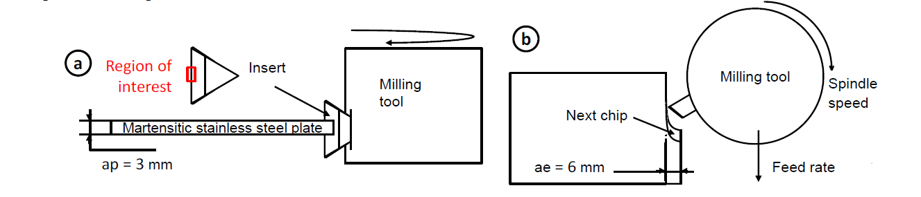
Fig. 1. Schematics of the experimental setup with (a) the side view and (b) top view.
In order to ensure a representative but simple configuration, the dry contouring of a thick plate with a single insert perpendicular to the machined surface was selected. 3mm thick discs were prepared and machined to obtain plates allowing straight contouring over 150mm for each pass. A dedicated fixture has been designed to fit them onto a Kistler 9257A dynamometer via two steel plates to avoid vibrations and uplifting during machining. Before each machined length, the surface was levelled by removing 0.3 mm via a preparation milling operation. A 60mm diameter tool was used in down milling, with a radial cutting depth ae fixed at 6mm (10% of the milling cutter). TPUN inserts were mounted and centered regards to the stainless steel plate in order to avoid cutting with the nose radius. Combined to a radial and axial cutting angles equal to zero, it resulted in an orthogonal cutting configuration.
2.3 Cutting insert configurations
TPUN 160304 inserts made of cemented carbide with between 7 and 10% of cobalt content were supplied by SECO Tools and characterized by a 11° flank angle and 0° rake angle. Three different grades were investigated and the cutting edge radius was assessed for each by averaging the measurements performed on 10 edges with an ALICONA InfiniteFocus microscope: (i) uncoated inserts (HX) with a mean edge radius Rb = 15 μm; (ii) PVD coated inserts with a single TiAlN layer (5μm) and a thin flash TiN layer on their flank face, Rb = 30 μm, fine grains carbide substrate (MP3000) and (iii) CVD coated insert composed of a TiCN layer (5μm) and an Al2O3 layer (2μm) with Rb = 40 μm and a coarse grains carbide substrate (MP1501).
3 Experimental results and Discussion
3.1 Operability region
According to the specific cutting configuration and the lack of data on this machined amterial in milling, the first step was to define the operability region into which tool wear tests could be properly carried out. A first experimental campaign was then performed based on the standard NF E66-520-6 (1999-09-01) AFNOR only with the uncoated insert, assumed to be the most critical cutting configuration. The criteria to qualify these cutting conditions were a limited flank wear, no unsteady cutting behavior, stable chip generation and specific cutting force. The latter was defined as shown in Equation (1), based on the resultant machining force recorded via a piezoelectric Kistler dynamometer at a sampling rate of 10kHz and the maximum chip thickness (Eq. (2)).

Where ap is the axial depth of cut, ae the radial depth of cut and f the feed rate.
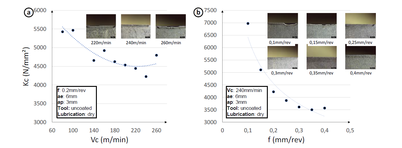
Fig. 2. Evolution of the specific cutting force (a) versus cutting speed with f = 0.2mm/rev and (b) versus feed rate with Vc = 240m/min.
A twostep procedure was applied using a new insert for each test over a 150mm long pass to cover both the range of cutting speeds and feed rates. This led to the identification of a minimum cutting speed of 180m/min (Fig. 2a) and a minimum feed rate of 0.3mm/rev (Fig. 2b) to ensure stable cutting conditions.
3.2 Tool wear tests
Based on the operability region previously defined, cutting conditions of Vc = 240m/min and f = 0.3mm/rev were selected to conduct the tool life tests. To monitor the wear evolution, a new insert was used for the following machining times: 1 minute, 2 minutes, 4 minutes, 8 minutes and 14 minutes. A Leica MZ125 binocular was used to measure the flank wear every minute for each insert while 3D topographies of the cutting edge were captured before machining and at each mentioned cutting times with x20 and x50 magnifications. The wear criterion to stop the tests was a flank wear exceeding 0.3 mm or the occurrence of a catastrophic wear.
Wear tests with uncoated TPUN inserts had to be prematurely stopped at 2 mins as catastrophic wear was observed. Severe chipping leading to the breakage of the cutting edges occurred corresponding to some wear types reported in the literature [9,10]. Moreover, the lack of coating promoted an intense adhesion of the material which could have potentially contributed to the attrition of the substrate i.e. mechanical removal of carbide grains. These results were thus discarded and could not be plotted versus time.
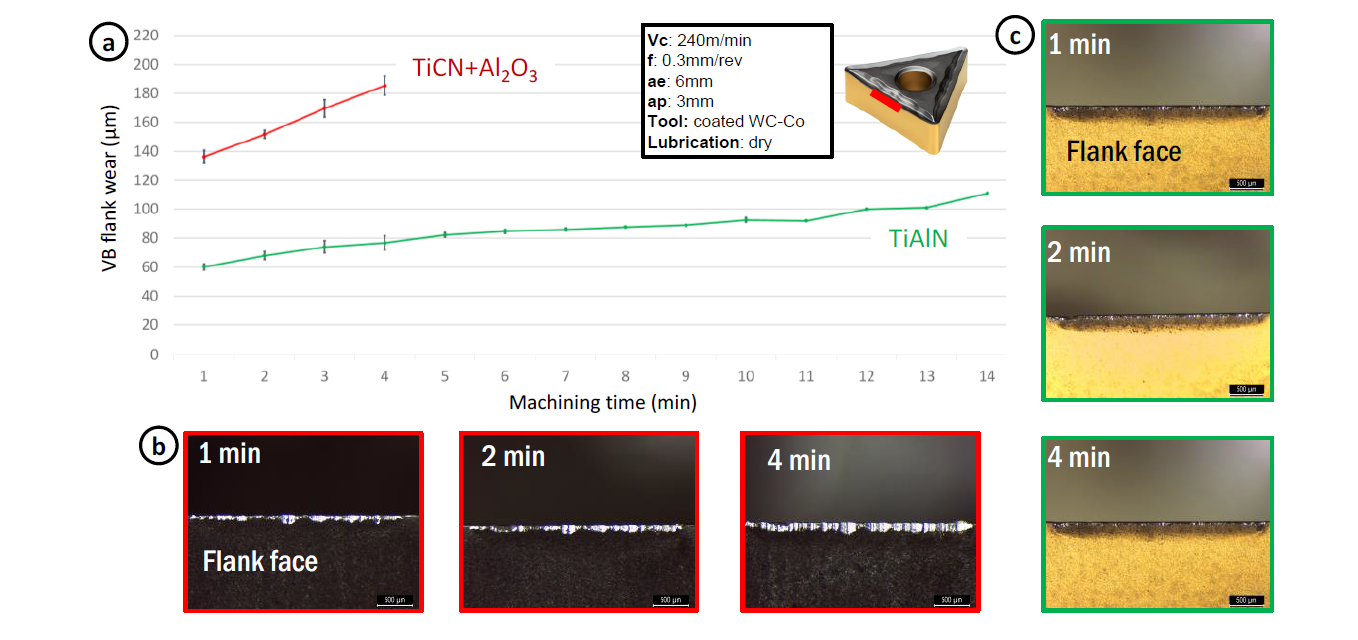
Fig. 3. (a) Evolution of the flank wear versus time with the TiCN+Al2O3 (red) and TiAlN (green) coatings and corresponding views of the flank face (b)(c).
The Figure 3a shows the evolution of the VB flank wear with each of the coated tools. A tool life of 4 minutes could be achieved with the CVD alumina coated inserts. The flank wear reached 0.14mm after one minute of machining and increased then steadily until forces became very high and led to the collapse of the edge and breakage. Optical images of the flank face (Fig. 3b) tended to show some adhesion on the cutting edge and removal of the coating.
Using a PVD TiAlN coating drastically improved the performance of the milling by extending the tool life to 14 minutes before the tool breakage (Fig. 3a). Flank wear appeared to be relatively uniform along the region of interest, despite some chipping at the depth of cut. Over the stable wear region, abrasion on the flank face and partial adhesion on the rake face and the cutting edge could be seen. This adhesion had no significant effect on the wear of this type of coating contrary to the CVD grade.
3.3 Wear modes
Scanning Electron Microscope (SEM) and Energy Dispersive Spectroscopy (EDS) analyses were conducted to investigate more precisely the mechanisms behind the observed wear. The cutting edge on the region of interest was imaged at x55, x200, x500 and x1000 magnification at the different time intervals with an acceleration voltage (HV) of 15kV and a working distance (WD) of nearly 15mm.
The alumina coating was found to be removed on the cutting edge with cavities caused by chipping promoting bonding of the 15-5PH (Fig. 4a). The EDS map (Fig. 4b) confirmed the predominant adhesion on the uncoated portion of the edge. Once this bonding breaks, pulling out of the carbide grains occurs amplifying the wear phenomena. Finally, cracks perpendicular to the cutting edge at regular intervals, corresponding to thermal fatigue cracks, could be observed at 4min of cut (Fig. 4a). The latter could be responsible of the collapse of the cutting tool just beyond this time. The coating plays an important role in thermal diffusivity and in the increase of temperature by friction. When the coating disappears, the contact with the substrate favors the temperature increase and therefore the adhesion of the 15-5PH. This periodic increase in temperature and the absence of coating expands the substrate and creates tensile stresses that generate fatigue cracks.
The same phenomena started to occur on the TiAlN coating from 8min of milling (Fig. 4c) but was still limited, leading to the use of the tool up to 14min. The PVD TiAlN seemed to have a beneficial effect on the fatigue strength of the insert as well as on the adhesion tendency (Fig. 4c). Indeed, a dominant and stable abrasion phenomenon on the flank face could be identified during the entire service life. However, when the coating disappears, material transfer takes place on the exposed substrate which appears less resistant to thermal cycles and results in the formation of cracks.
Interestingly, in both cases, the chromium elements migrated to the rake face while iron remained on the cutting edge and especially the substrate. This could confirm a different affinity of the stainless steel and a potential oxidation wear mechanism.
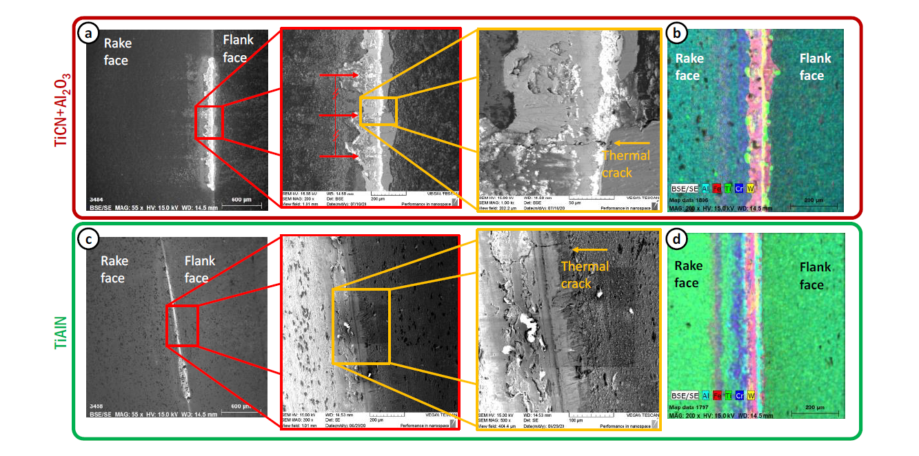
Fig. 4. SEM images of the Al2O3 (a) and TiAlN (b) coated inserts and corresponding EDS maps (b)(d)(Fe being red, Al light blue, Ti green and W yellow).
4 Numerical approach and Discussion
4.1 Multi-scale numerical model
The observed wear modes are the result of a strong coupling between adhesion and thermal fatigue. To improve the understanding of their occurrence, an analysis of the thermomechanical loadings withstood by the cutting tool and thermal phenomena specific to milling was proposed.
A numerical approach combining different models at different scales was developed as presented in Figure 5.
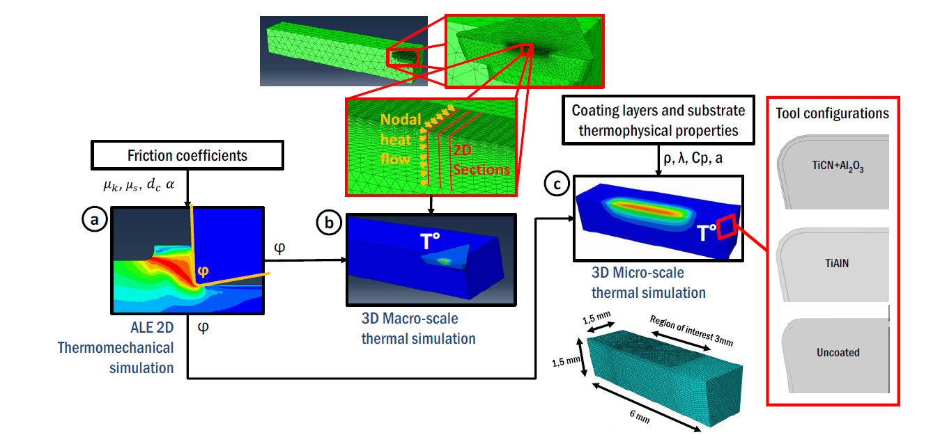
Fig. 5. Numerical approach based on: (a) a thermomechanical model, (b) a 3D pure thermal simulation at the macro-scale and (c) a 3D thermal simulation at the micro-scale taking into account the various coating layers and their properties.
The 2D ALE model (Fig. 5a) was used to assess the thermomechanical loadings applied along the tool-chip contact zone. Details of this development can be found in the work of Mondelin et al. [11] especially regarding the parameters of the Johnson-Cook constitutive model and the boundary conditions. To take into account the coating in this model, the friction formulation in Equation 3, as well as heat partition coefficient, were updated depending on the considered tool configuration. Friction data from Mondelin et al. [11] were selected for the uncoated and Al2O3 inserts. As no data were available with a TiAlN coating, using friction data on a 42CrMo4 with a TiN coating [12] was considered to be a consistent alternative. 42CrMo4 does not have the same adhesion tendency compared to the 15-5PH but as the TiAlN exhibited a limited adhesion during the milling wear tests, it was assumed to be a reasonable hypothesis. The parameters used for each configurations are summarized in Table 2.

Table 2. Parameters of the friction formulation (Eq. 3) for the various simulated tool configurations and α the heat partition coefficient.

The heat flux extracted from the ALE model on each node at the contact interface were then used as boundary conditions in a 3D full scale model (Fig. 5b) and a sub micro-scale model defined at the scale of the coating layers (Fig. 5c), and pulsed at the cutting frequency. The 3D full scale model was only used to assess the consistency of the boundary conditions of the micro-scale model and to properly define the volume to be modelled. In this one, the thermophysical properties of each coating layer were implemented based on the data from the literature [13-15] and meshed with a single layer of elements.
4.2 Numerical results
The Figure 6 displays the results provided by the different models. The Figure 6a shows the impact of the friction formulation on the contact pressure and sliding velocity distribution at the tool chip interface.
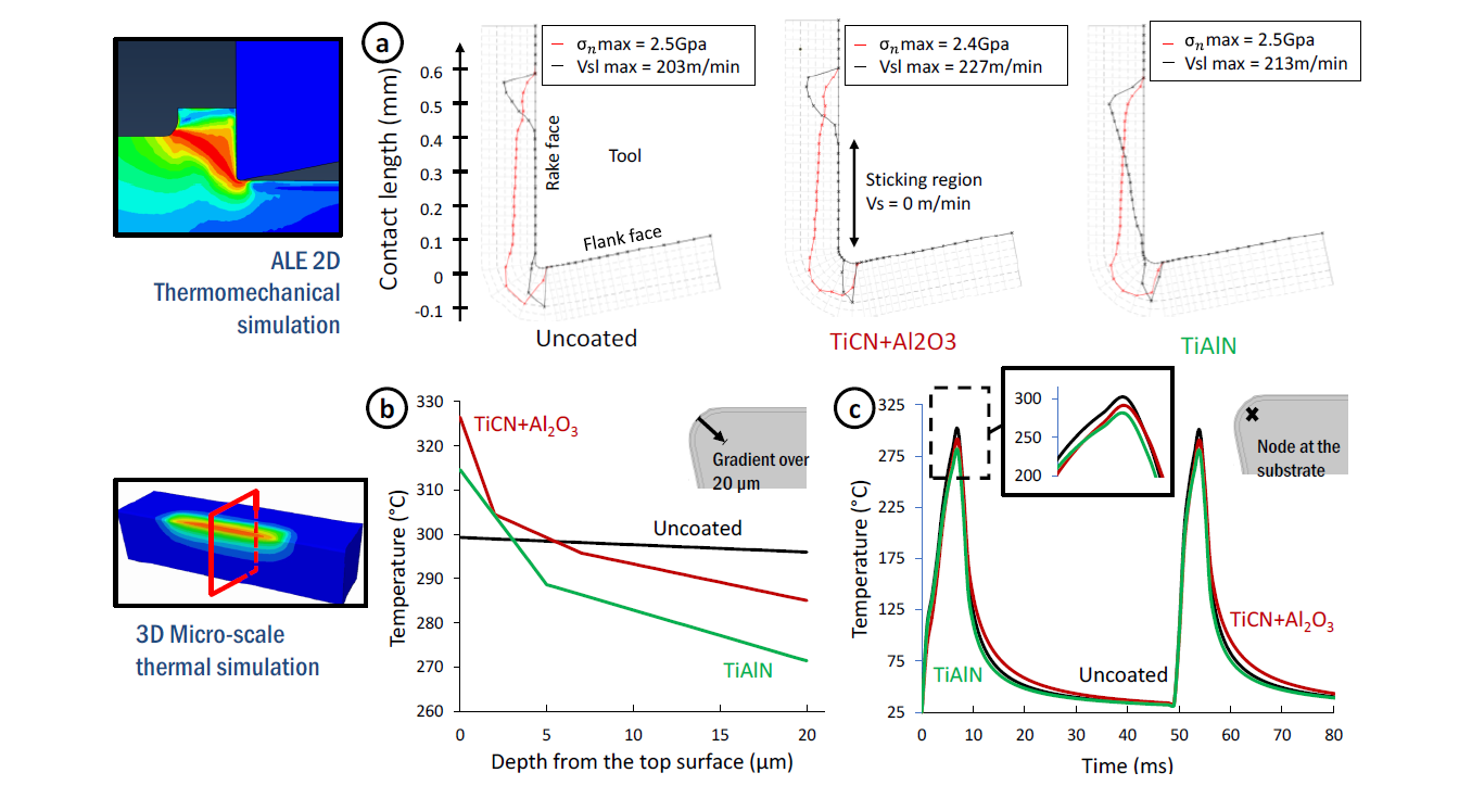
Fig. 6. (a) Simulated thermomechanical loadings with the three tool configurations; (b) temperature across the coatings and substrate; (c) evolution of the temperature versus time at the surface of the substrate.
While the uncoated and alumina coated tools presented both a sticking region over the first 0.4mm of the contact zone, a much larger sliding region could be observed on the simulated TiAlN insert with a sticking zone limited to 50μm. Keeping in mind the assumptions on the input data, these results seem to corroborate the experimental trends showing that adhesion was more severe when using a Al2O3 coated tool and that abrasion was the dominant wear mode with the TiAlN coating. However, the three configurations led to the same maximum contact pressure of 2.4-2.5GPa located at the cutting edge radius, showing that these tribological considerations only do not explain the crack formation previously reported.
Temperatures were thus extracted from the micro-scale model after the first two heating cycles. The profiles presented in Figure 6b show that the top surface temperature could be higher when cutting with the Al2O3 coated tool even if it becomes lower once it diffuses within the substrate. Indeed, due to its low thermal conductivity, alumina acts as a thermal barrier preventing heat to diffuse but at the same time generating a temperature increase at its extreme surface. This phenomenon can be seen with the TiAlN coating as well but to a lower extent. One can also notice that the thermal gradient within the Al2O3 layer is more pronounced. If the difference in terms of temperature amplitude could be seen as negligible, the number of thermal cycles withstood by the cutting tools has to be emphasized: 2500 cycles for the uncoated insert, 5000 for the alumina coated insert and 17 500 cycles for the TiAlN coated insert. The Figure 6c also shows that the substrate is indeed exposed to a 300°C difference in only 6ms corresponding to a high heating rates of 50000°C/s. This tend to confirm the hypothesis that tool breakage occurs due to thermal fatigue and that the coatings can be seen as a way to delay its initiation by keeping the substrate not exposed to the thermal source.
5 Conclusions
This paper proposed a preliminary investigation of wear modes when milling a 15-5PH martensitic stainless steel. A simplified orthogonal setup has been developed to perform wear test, assess the contribution of a coating and identify the dominant wear modes. A numerical methodology was employed to extract local data such as the loadings onto the tool and temperatures within the coatings and the substrate
It was shown that a PVD TiAlN coating can drastically enhance the machining performance in milling of such alloys compared to a Al2O3 coated tool. It especially exhibited a lower adhesion tendency which delayed the occurrence of tool breakage. If chipping cannot be completely avoided, adhesion is thought to generate a pilling of the coating and thus the exposure of the substrate. Material transfer then takes place preferably on the cemented carbide substrate activating its attrition and amplifying the coating degradation. Findings from this experimental campaign, combined to the numerical results, tend to confirm that tool failure is mainly governed by a thermal fatigue phenomenon once the substrate is exposed. Extending the tool life would require the annihilation of material transfer to be able to protect the substrate but could be achieved by investigated alternative coating or substrate post-processing techniques to improve the residual stress state and thus the fatigue life.
