1 Introduction
Thermoforming is an attractive manufacturing process for high-volume, low-cost production of composites parts, and simulation is a valuable tool to guide the design of the processing parameters that can result in producing high-quality continuous fiber-reinforced composite parts. A credible simulation requires the input of material properties and an associated material characterization program that documents the shear, tensile and bending mechanical behaviors, as well as frictions involved in the process. A typical thermoforming process consists of a preform phase that transforms a set of laminates to a near-net-shape ply stack, and a subsequent consolidation phase that employs pressure and heat to join a set of the preforms into a final part. Friction plays a critical role in the preform phase of the manufacturing process.
In thermoforming, a flat sheet of material is located between the female/tool die and the binder ring/draw ring. Pressure is then applied to the binder ring, and the combination of the normal force from the binder ring, and the friction at the top and bottom of the tool/ply interfaces induces an in-plane tension in the sheet. While the binder ring is adding tension to the edges of the material, the rest of the material can undergo shear, allowing it to conform to the shape of the tooling. This in-plane tension mitigates the development of out-of-plane wrinkles and in-plane waviness. However, care must be taken as to the magnitude of the in-plane tensile force. Too little force, and a localized compression state can develop, and then local wrinkling and waviness can occur. Too much force, and the laminate can tear.
Intra-ply shear is the dominant mode of deformation during the forming process, and various degrees of material shearing are what allows the material to conform across a compound curvature part. Adding complexity to the forming process outcome is the increase in thickness of the lamina due to conservation of volume during in-plane shear. Dangora et al. [1] verified the incompressibility phenomenon with micrographs taken of laminates of DSM Dyneema HB80 sheared to 0°, 20°, and 60° showing the associated thickness increases corresponding to volume conservation. Based on that research, variations in thickness can be directly linked to variations in shear. The implications of thickness changes during the process are two-fold: (1) thickness variations in the preforms and (2) effects on friction during the forming.
After the preform step, heat and pressure are used in combination with matched dies to consolidate the preform(s) and cure the part. Fig. 1 depicts how thickness variations in individual preforms can lead to poor-quality consolidation and voids due to pressure variations. Therefore, these thickness changes must be considered in a forming simulation.
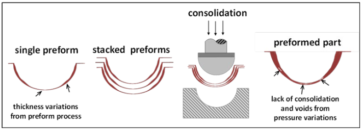 Fig. 1. Variations in preform thickness leads to inconsistent/poor consolidation.
The thickness changes due to shearing also affect material surfaces involved with frictional interactions. The friction between the binder ring and the material adds tension so that the material undergoes shear, even under the binder ring.
Researchers have been working to understand the role of friction in the forming process for many years. Studies have shown that friction between two sliding surfaces can create unwanted outcomes such as distortions in the final part shape, residual stresses, and wrinkles [2-6]. Moreover, in the use of binder rings, this friction can help to reduce the formation of wrinkles with an appropriate pressure [1, 7-11]. Hemisphere preforming trials accomplished by Dangora et al. [1] showed the reliance on binder-ring pressure in regulating the size and appearance of wrinkles for a unidirectional cross-ply material system, DSM Dyneema HB80.
This paper will present results from single-layer experimental hemisphere forming trials of DSM Dyneema HB210, using two different binder-ring pressures. Results from elevated temperature friction testing are incorporated into a LS-DYNA, a commercially based software, hemisphere preforming simulation to evaluate the applicability of various element formulations based on thickness changes. The importance of interaction between thickness changes and friction values is established by comparing the simulation punch force results to experimental results. An investigation of friction and binder-ring pressure sensitivity is completed with the element formulation conclusions.
2 Methodology
2.1 Experimental Hemisphere Preform
Hemisphere preform experiments were carried out using the experimental setup shown in Fig. 2. The punch was attached to the crosshead of the Instron Universal Testing Machine, and load and displacement data were recorded. After the laminate sheet was in place, free weights were placed on top of the binder ring to develop a pressure on the laminate. The entire setup was located inside an Instron oven to heat the material to the desired testing temperature. The crosshead descended at a rate of 6.35 mm/sec to mimic the conditions of the actual preform process.
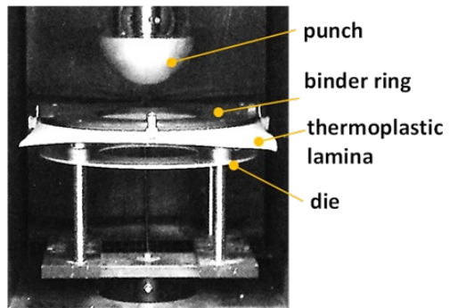 Fig. 2. Experimental preform experimental setup.
The hemisphere preform has a punch radius of 76.2 mm, and the laminate blank used in the process is 381 mm x 381 mm. The punch is pushed through the material farther than the radius so that an extended hemisphere shape is formed with flat sides to make the part slightly more complex than a pure hemisphere.
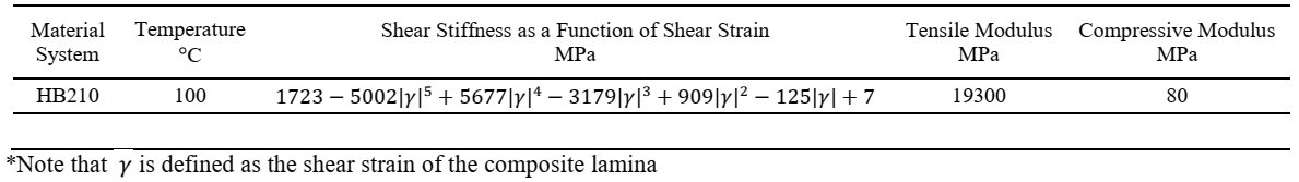
The composite laminate system investigated in this research is DSM® Dyneema HB210. This material system is a thermoplastic cross-ply containing four unidirectional layers oriented in a (0/90)2 fiber configuration with each ply comprised of UHMWPE fibers and a thermoplastic polyurethane (TPU) based matrix [12]. The tensile, shear and bending properties at 100°C for Dyneema HB210 is provided from previous testing [13-15] and shown in Table 1.
Table 1. Material Properties for Hemisphere Preforming Simulations.
 2.2 Modeling Approach
The Sherwood Group [16] has developed a discrete modeling approach that was successfully used to simulate the forming of a plain-weave hemisphere shape. Conventional elements available in commercial finite element software are used in the unit cell approach shown in Fig. 3. Fiber directionality is described and tracked by beam elements that represent the tensile and flexural properties of the laminate. The shear load is carried by shell elements that capture the evolution of the in-plane shear stiffness as a function of the degree of shear. In the case of a woven material, the horizontal and vertical beams represent the warp and weft tows with respective material properties. In the case of a 0/90 cross-ply, the horizontal and vertical beams can be assigned tensile and flexural properties of the 0° and 90° layers.
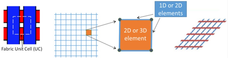
Fig. 3. Unit cell configuration for mesoscopic laminate material model.
Plane-strain shell elements are widely used to model the in-plane shear behavior of laminate forming, but this class of shell elements does not capture the thickness changes caused by shearing, compression and/or stretching. The element formulations in LS-DYNA that can model through-plane strains were evaluated, and one formulation was chosen for further consideration. The LS-DYNA thickness-enhanced shell formulation (thick-thin shell), SHELL ELFORM25, is a general shell element that includes an additional feature of linear strain through the thickness compared to a Hughes-Liu general shell element. Loading and contact of the surface are possible to allow for tooling and laminate plies to interact when contact algorithms are defined [17]. The thickness stretch of the element requires a 3D constitutive model, but the element is defined by a midsurface with only four nodes (Fig. 4).
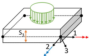 Fig. 4. Unit cell configuration for mesoscopic laminate material model.
Evaluation of this element choice required that the user-defined (UMAT) discrete mesoscopic material model used in LS-DYNA consider 3D material behavior. The in-plane tensile behavior is still carried by beam elements that provide directionality to the elements carrying the shear load. The in-plane shear behavior as a function of shear angle remains the same as the plain-strain implementation. However, through-plane stress and strain are updated in the UMAT, whereas general shell elements do not have strain in that direction. Validation of the shear behavior application was done through comparison to shear-frame, also known as picture-frame, experimental results conducted with a constant crosshead rate of 2 mm/sec [15].

Fig. 5. Hemisphere preform simulation in LS-DYNA showing (a) all parts and (b) relevant areas of tool/ply friction.
The hemisphere preform simulation as shown in Fig. 5 is modeled after the experimental presented Fig. 2. Binder-ring pressure and friction act together to produce tension in the laminate, so those two boundary condition parameters are areas of interest in the hemisphere forming model. A binder-ring pressure of around 1 MPa is used for the actual preforming process being simulated. However, the current laboratory preforming setup can only achieve a binder-ring pressure of 5750 Pa using free weights. Simulations using both the experimental binder-ring pressure, as well as binder-ring pressures from the actual process will be evaluated to gain an understanding of how the binder-ring pressure will affect this material system.
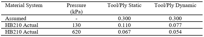
The friction interaction is what allows the binder pressure to induce tension in the material, testing for experimental values was performed. Campshure et al. [18] updated the existing University of Massachusetts Lowell test apparatus for measuring the static and dynamic coefficients of friction for Dyneema HB210. This updated test system can be used to find the static and dynamic ply/ply and tool/ply coefficients by pulling a specimen through heated pressure plates. An air-spring system exerts the normal force, and this airspring is feedback-controlled by compression load cells. Applied normal forces were directly related to the range of binder-ring pressures of interest for the specific thermoforming process, as were pull velocities and platen temperatures.
The values shown in Table 2 are a result of averages between fiber orientation and resin condition, as the hemisphere symmetrical with each condition represented equally. Simulations using both sets of friction values were performed for comparison. Single-layer simulations were completed and compared to single-layer experimental results.
Table 2. Friction Coefficients used in Simulations.
3 Results and Discussion
Laboratory experiments of hemisphere forming were completed to investigate how punch force varies as a function of the material choice and binder-ring pressure. Hemisphere preform experiments were performed on a single layer of Dyneema HB210. Free weights were placed on top of the binder ring to apply pressures corresponding to 3230 Pa and 5750 Pa. Examples of the preformed specimens of HB210 are shown in Fig. 6.
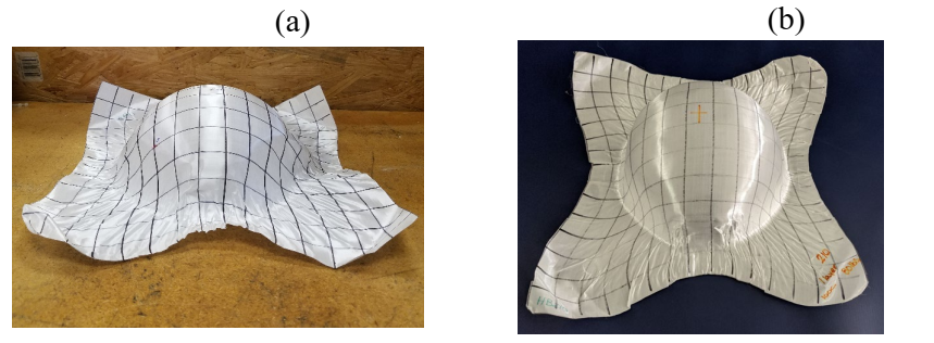 Fig. 6. Single-layer preform specimen for Dyneema HB210 (a) with 3230-Pa binder-ring pressure and (b) with 5750-Pa binder-ring pressure.
Visual inspection of the samples indicates the lower binder-ring pressure (3230 Pa) applied to Dyneema HB210 was not high enough create the tension needed to deform the laminate into a hemisphere shape (Fig. 6(a)). However, by increasing the binder-ring pressure to 5750 Pa, the hemisphere shape was retained (Fig. 6(b)). This inability of the binder ring to hold the laminate in place to keep it deforming is reflected in the punch force shown in Fig. 7.
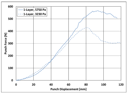 Fig. 7. Single-layer experimental preforming punch force at two applied binder-ring pressures for Dyneema HB210.
The ramped increase of load at the beginning of the curve represents the steady shear deformation until the 85-mm crosshead displacement. At that point in the process, there is a leveling off in the case of 5750-Pa binder pressure, coinciding with the small wrinkles forming around the binder ring. However, in the case of the 3230-Pa binder-ring pressure, the load drops when it is pulled through the binder ring and die without further deformation. In Fig. 6, many small wrinkles can be seen around the edge where the binder ring was applied, with somewhat larger wrinkles on the upright sides of the hemisphere shape in the front, back and two sides.
The LS-DYNA simulation was then used to simulate the same hemisphere forming that was done in the experiments. Fig. 8 shows a comparison the experimental and simulation results of punch force vs. crosshead displacement results for HB210 at 100°C with a binder-ring pressure of 5750 Pa. The experimentally derived friction values were used in the simulations, which employed both planestrain element ELFORM6 and thickness stretch element ELFORM25 for evaluation. The inability of the ELFORM6 shell element to thicken during the simulation leads to punch forces much lower than experimental values. However, the thickness stretch ELFORM25 shows relatively good punch force agreement with the experimental data, thereby implying the need for including thickness changes in a forming simulation. Measured forces in the simulation begin to deviate from the experiment when folds in the material under the binder ring begin forming. However, the leveling off of the curve coincides with the experimental leveling off, indicating the formation of wrinkles at that point in the process.
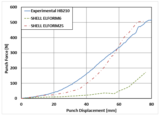 Fig. 8. Punch force comparison between SHELL ELFORM6, SHELL ELFORM 25 and experimental values for Dyneema HB210.
Based on the ability of SHELL ELFORM25 thickness stretch shells to capture the punch force better than the SHELL ELFORM6 plane-strain shells, SHELL ELFORM25 was used in binder-ring pressure comparison and friction value comparisons. Fig. 9 compares the experimental values for two binder-ring pressures to the LS-DYNA simulation values. Nice correlation is made with experimental values, including the onset of wrinkling; however, the simulation shows a larger decrease in force with decrease in binder-ring pressure than the experimental values. Much of this discrepancy can be contributed to the buckling of hinged trusses when wrinkling under the binder ring begins.
For investigating the model sensitivity to friction, an arbitrary tool/ply value of 0.3 was used. This value is more than three times higher than the experimental coefficients but is sometimes a generic value used by researchers in forming simulations when no experimental coefficients are available. Fig. 9 shows that the force ramped up much more quickly than models with the experimental friction coefficients, indicating that the simulation with thickness changes is sensitive to changes in friction and experimental friction values should be used.
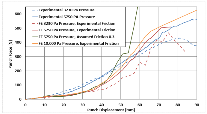 Fig. 9. Finite element simulation results compared to experimental results for single-layer Dyneema HB210 at 100°C hemisphere preforming.
Although the simulation did not extend past the hemisphere form as in the actual experiment, Fig. 10 shows that the wrinkle development compares well with more wrinkles developing with the lower binder-ring pressure.
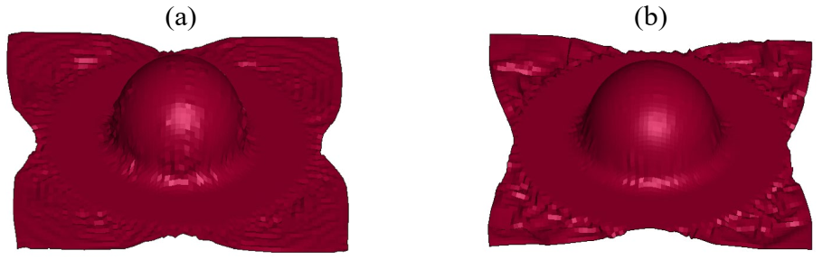
Fig. 10. Wrinkle development in LS-DYNA simulation for HB210 (a) 3230-Pa binder-ring pressure and (b) 5750-Pa binder-ring pressure to match with experiments.
Although 1 MPa is the actual binder-ring pressure used with at least 20 layers of laminate, that binder-ring pressure causes tearing and tension-based wrinkling in a single layer. However, the simulation can be used to target a binder-ring pressure that can minimize the wrinkling around the part. Fig. 11 shows the simulated preform when 10,000 Pa binder-ring pressure is used, showing minimal wrinkling around the rim of the hemisphere shape. The punch force curve in Figure 10 also shows that the load does not drop, indicating that there is no clear onset of wrinkling. Visually there are undulations near the edge of the binder ring as a result of the gap between the tooling and the binder ring. The simulation could be used to design a binder ring that would minimize the undulations, or more layers of material could be used would fill this gap and result in a smooth part.
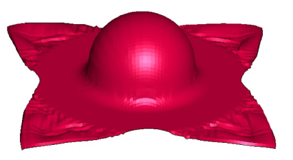
Fig. 11. Wrinkle development in LS-DYNA simulation for HB210 using 10,000-Pa binder-ring pressure to minimize wrinkling.
Based on the punch force results and friction sensitivity, incorporating thickness changes into the shell element is integral to a high-fidelity forming model. The LS-DYNA thickness stretch ELFORM25 is an efficient, commercially-available element that can carry the in-plane shear behavior, as well as thickness changes, of a unidirectional cross-ply laminate in forming.
4 Conclusions
In this research a set of hemisphere preforming experiments were performed on a unidirectional thermoplastic cross-ply material systems materials, DSM Dyneema HB210. Results showed that although increased binder-ring pressure resulted in wrinkle reduction, the slope of the binder ring force was related to the shear stiffness of the material and not the binder-ring pressure. However, the peak of the curve was increased with increase binder-ring pressure and the onset of wrinkling under the binder ring. The experimental results were used to justify an element choice for LS-DYNA simulations of the preforming process. The SHELL ELFORM 25 thickness stretch element was shown to better replicate the experimental punch force for two materials with differing shear stiffness than the SHELL ELFORM6 plane-strain element because of its ability to thicken in shearing during the simulation. Simulations with varying binder-ring pressure and friction were also completed for validation. The simulation was used to target a binder-ring pressure that would minimize wrinkling for one layer of HB210 with the given tooling. The LS-DYNA ELFORM25 thickness stretch element has been shown to be an accurate element for the use of single-layer thermoforming process simulation. This research highlights the need to incorporate thickness changes and experimental friction values for punch force validation in thermoforming simulations. Likewise, the use of experimental friction values instead of the assumed 0.3 was shown to increase the accuracy of the model. The next step is to increase the number of layers, both experimentally and in the simulation.
Acknowledgements
Support for this research was also provided by the Army Research Laboratory under Cooperative Agreement Number W911NF-18-2-0033. The views and conclusions contained in this document are those of the authors and should not be interpreted as representing the official policies, either expressed or implied, of the Army Research Laboratory or the U.S. Government. The author would like to express thanks to DSM for providing Dyneema HB210 material for this research.
