1 Introduction
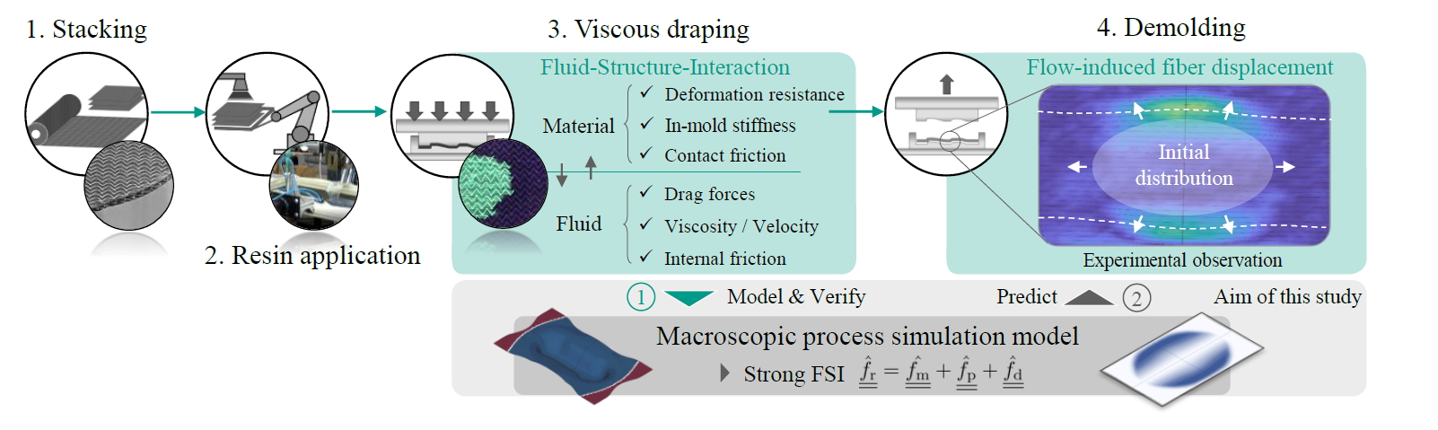
Fig. 1. Graphical abstract | Flow-induced fiber displacement during viscous draping in wet compression molding (WCM)
Wet compression molding (WCM) provides large-scale production potential for continuous fiber-reinforced structural components due to simultaneous infiltration and draping during molding [1-4], often referred to as viscous draping (cf. Fig. 1) [4-5]. Similar to other liquid molding techniques (LCM) such as vacuum assisted resin infusion (VARI) [7,8] or resin transfer molding variants (HP-RTM, PC-RTM, C-RTM) [9-12] a strong interaction between fabric stack and resin can lead to flow-induced fiber displacement or even fiber washout [13], which can provide serious challenges in terms of process control and part performance. This interaction is a crucial issue in all LCM variants mentioned here and has been the subject of a great deal of research in recent decades. Comprehensive reviews on key mechanism and modelling approach regarding LCM processes are provided among others by Trochu et al [14], Simacek et al. [15] and Michaud [16].
Although free surface flows and flow-induced fiber displacement is avoided wherever practicable, it cannot be prevented completely, especially when dealing with more complex geometries or unsuitable process parameters. Recently, Hautefeuille et al. [17] and Bodaghi et al. [13] demonstrated the ongoing relevance and challenges regarding a proper process control to prevent flow-inducted fiber displacement during RTM processes. Moreover, comparable concerns are reported by Albrecht et al. [18] and Muthuvel et al. [19] for viscous compaction during WCM processes, where these effects are even more likely due to additional simultaneous draping. Seong et al. [20] experimentally demonstrated that two types of deformations should be distinguished. A local flow-induced deformation can be expected when flow forces exceed the in-mold stiffnesses of the material and frictional forces are sufficiently high, whereas a global (rigid body) sliding of the reinforcement is primed when flow forces exceed the frictional forces at the interfaces between reinforcement and ply as well as between individual layers. Bodaghi et al. [9] presented a one-dimensional analytical model to predict fiber-washout during RTM. Still, complexity and non-linearity of the involved mechanism prevent a suitable analytical assessment for more complex cases. Although several numerical approaches have been published as outlined above, in-plane flow-induced fiber-displacement has only been addressed by one-dimensional test cases [21]. Commonly, deformation is taken into account in terms of local compression or fiber-orientation, but no within a strong coupled modelling approach including both a fluid model and a material specify deformation model suitable for large deformations. As this is only a first step, this paper focuses on the suitable representation of the through flow-induced fiber displacement. This neglects modelling of superficial fluid and its coupling to the deformable porous medium [22].
Outline. In this work, a formerly presented macroscopic modelling approach for three-dimensional fluid progression during draping [6,23] is enhanced by strong Fluid-Structure-Interaction (FSI) based on Terzaghi’s law. For this purpose dry and pre-infiltrated compaction trials on a non-crimped fabric containing unidirectional ZOLTEK fibers (Panex PX35) are conducted to parametrize and verify the models’ response. Subsequently, a parametric study is conducted to evaluate the impact of tool-ply-friction on resulting flow-induced in-plane deformation. Finally, a qualitative comparison with the results reported by Hautefeuille et al. [17] for a comparable material is presented.
2 Process simulation model
2.1 Constitutive Equations
The extended three-dimensional process simulation approach for WCM utilizes a fully-coupled forming and fluid submodel implemented in ABAQUS/EXPLICIT to account for large deformations and simultaneous fluid progression. This is enabled via stacked built-in continuums shells and user elements representing the single plies in a finite element manner. Forming behavior addresses membrane, bending, contact and compaction behavior, whereas the fluid submodel accounts for the solution of the pressure field, transient flow front progression and mass conservation. The formerly proposed model [23] included a weak coupling between fluid and material, meaning that deformation leads to pressure and flow progression, but not vice versa. This is not sufficient to address flow-induced fiber displacement where a strong coupling is required. First, the originally proposed model for woven fabric needs to be adapted to account for UD-NCF material, both in terms of forming and form filling.
Regarding the forming submodel, a highly suitable membrane material model presented by Schirmaier et al. [24] is applied within the continuum shell element. The model is parametrized by means of off-axis-tension tests (OAT) in dry state. The macroscopic, hyperelastic-plastic material model is formulated with respect to the principal directions via linear strains 𝜀⊥ with special consideration of the perpendicular direction according to:

Total material response in terms of Cauchy stress σ̳̂ in ABAQUS’S Green-Naghdi frame [𝑥̂, 𝑦̂] is obtained by combining the Cauchy stress σ̳̂Ph in principal direction and perpendicular to the fiber orientation σ̳̂⊥.Usage of linear strain measures reduces the non-linearities to constitutive law itself [24]. In addition to membrane behavior, compaction behavior in thickness direction needs to be adapted which is outlined in Section 2.2.
To adjust the fluid submodel, permeability values in fiber direction 𝐾f1, perpendicular 𝐾f⊥ and in thickness direction 𝐾3 are required. To measure in-plane permeability in undeformed state, experiments presented by Albrecht et al. [18] and additional trials using a linear setup presented by Magagnato et al. [25] are conducted. Moreover, transversal permeability in thickness direction is measured at the Fraunhofer IGCV in Augsburg (Germany). Permeability values are implemented based on the current fiber volume content (fvc) 𝜙 via

Finally, a strong coupling between fluid pressure and deformation is introduced using Terzaghi’s effective stress according to MacMinn et al [21]. To accomplish this, two additional sources for nodal reaction forces within ABAQUS’S Green-Naghdi’s frame [𝑥̂, 𝑦̂] are introduced to the isoparametric user element. The first one representing the reaction forces caused by the fluid pressure f͇̂p within the skeleton structure of deformable porous medium and the second one representing the fluid drag f͇̂d between flow and fabric. The pressure itself cannot lead to deformation within an element cell, since the material is assumed to be incompressible [16]. Combined with the implemented dry material response in thickness direction f͇̂m, the entire material reaction yields
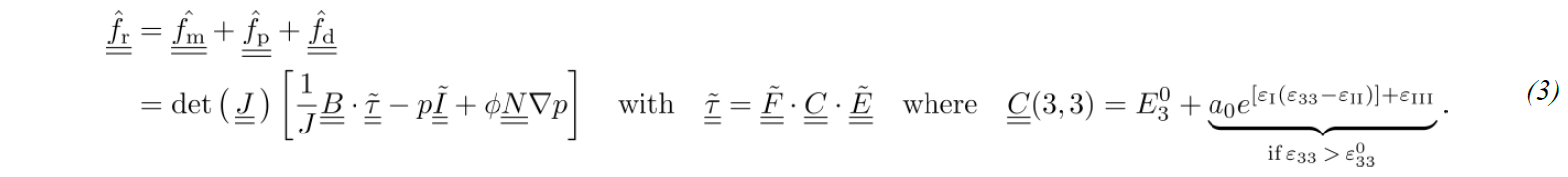
Here, B͇ provides the operator matrix of the user element, 𝐽 the Jacobean determinant, 𝜏̳̃ the Kirchhoff stress tensor in Voigt Notation, F͇̃ the deformation gradient, Ẽ͇ the Green-Lagrange-Strain tensor, N͇ the shape function matrix and C͇ the stiffness matrix [23]. In addition, gravity is accounted for within the forming and fluid submodel using built-in methods and by means of an additional body force during the solution of the pressure field, respectively.
2.2 Parametrization and verification
To parametrizes transverse compaction behavior of the UD-NCF, dry compaction trials with a six ply stack are carried out using a punch-to-plate setup [6] as displayed in Figure 2 (a). Reaction forces reveal a commonly observed non-linear increase towards high compaction states. Nesting effects seem to be of minor importance as two different layup’s [0]6 and [0/90/0]s provide comparable results.

Fig. 2. Parametrization and validation | (a) Experimental setup and reaction forces during dry and viscous compaction; (b) Simulation setup for the dry stack compaction; (c) Setup and pressure distribution during viscous compaction
To identify suitable material compaction parameters, simulations with the experimental setup as displayed in Figure 2 (b) are conducted. Parameters are optimized with respect to the obtained reaction force (cf. Table 1). The non-linear material response in thickness direction is implemented according to Equations (3), which is superimposed to the solver-required built-in stiffness 𝐸330 of the continuum shell for compaction beyond 𝜀330. Dry model response is marked with black dots in Figure 2 (a).
Table 1. Compaction parameters for UD-NCF

Pre-infiltrated compaction experiments are conducted in order to verify the introduced additional fluid response within the model. Experimental results show a strong increase in reaction force and a shift towards lower compaction states when fluid is present. This is consistent with other results reported in literature [6,26] as the additional fluid pressure superimposes to the material response. Once again, layup difference does not appear to significantly affect the obtained results. To verify the introduced FSI, a setup with pre-infiltrated plies is used according to Figure 2 (c) to predict the reaction forces during viscous compaction. Stack size and outlet position match with the size of the punch. Since free surface flows are not addressed with the current modelling approach, flow through and above the reaming material outside the punch area cannot be accounted for yet. However, a good agreement between experimental solution and numerical prediction justifies this approach. Moreover, impact of gravity within the pre-infiltrated stack can be observed, slightly reducing the obtained reaction forces in contrast to a purely in-plane approach.
3 Parametric study
Seong et al. [20] reported, that individual material structure, deformation conditions (e. g. compaction state or frictional conditions) and process boundary conditions (e.g. injection rate) determine whether local deformation or rigid body slip occurs when a strip of material is infiltrated with a constant flow rate under constant compaction. In the following, a comparable numerical study on a fully pre-infiltrated strip under constant compaction rate is carried out to evaluate whether these effects are also relevant for WCM process and are predicted by the model. Even though the investigated material and specimen size in this study is not the same, similar determining mechanism are expected. A viscous compaction scenario is chosen for this study, to represent the WCM process.
A fully pre-infiltrated strip (100 x 10 mm) containing the above outlined UD-NCF material model is compacted with constant compaction rate of 0.05 mm/s between two parallel rigid surfaces (cf. Fig 3). The left side of the strip is pinned and an outlet is defined at the opposite nodes on the right side. Remaining nodes are unconstrained. Fiber orientation is set to 90 degrees to maximize the effect of flow-induced fiber displacement. The flow direction itself is perpendicular to the fiber direction. A constant viscosity of 100 mPas is assumed. To assess the impact of friction conditions at the interface between ply and tool, three different maximal shear stresses 𝜏min,𝜏mid,𝜏max are presubscribed at the interfaces in addition to a friction coefficient of 0.2. The contact model itself is penalty based. The center value 𝜏mid=1𝑒−4 N/mm² is derived by assuming a fluid surface layer thickness of 0.01 mm and a maximal fluid viscosity of 10 mm/s and the fluid to be Newtonian. Other values are obtained by using a scaling factor of 10 leading to 𝜏min=1𝑒−5 N/mm² and 𝜏max=1𝑒−3 N/mm². Average fiber-volume-content ranges between 42 and 50 %, depending on the degree of in-plane deformation caused by fluid forces.
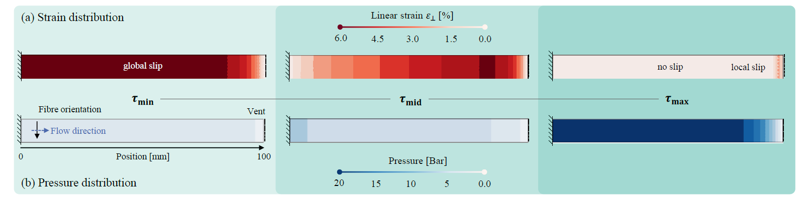
Fig. 3. Parametric study | Impact of contact formulation on predicted flow-induced strains and pressure distribution for a fully pre-infiltrated specimen at time point 𝑡1=0.6 s
Considering a specific point in time during compaction, low friction values lead to globally pronounced slip within the specimen, indicated by non-zero strain for all other nodes than the pinned ones. In contrast, increased friction reduces or even prevents this, at least for a certain amount of time (cf. Fig 3 (a), 𝜏max). In this sense, strain is reduced from global to a local area near the vent when friction increases. Consequently, arising fluid pressures (cf. Fig 3 (b)) are much higher under high friction conditions, because the fluid needs to progress throughout a relatively long path of higher compacted porous medium.
To increase vividness, resulting quantities, namely displacement, perpendicular strain and pressure are plotted along the strip in Figure 4. Moreover, two time steps at 𝑡1=0.6 sec. and 𝑡2=1.8 sec. are displaced. A one-dimensional non-linear pressure distribution from the left to the right end of the strip occurs during all trial, following the applied boundary conditions. As indicated above, friction conditions within the mold have a huge impact on all displaced quantities. Beyond that, two different deformation modes are observed. When friction forces are low, deformation develops inside-out, meaning that strains firstly arise at the center, whereas increases friction has an inverse effect. In the latter case, deformation starts outside-in, first strains are found near the outlet.
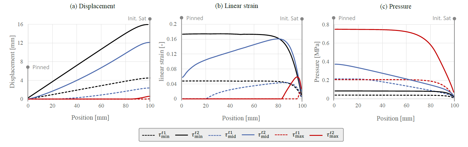
Fig. 4. Parametric study | Flow-induced displacement, strain and resulting pressure distribution along a fully pre-infiltrated specimen during compaction for different maximal contact stresses
These results are consistent with the conclusion drawn by Seong et al. [20] for the investigated infiltration test case. When assuming a reasonable amount of friction (≥𝜏mid) between material and tool, deformation starts locally from the outside and progresses towards the center. Thereby, it constantly reduces the remaining tangential contact forces until rigid body deformation occurs. The resulting overall displacement depends on the in-mold stiffness of material, which is very low when flow direction is perpendicular to the reinforcement’s.
4 Comparison with literature
In their experimental study on viscous compaction of a quasi uni-directional weft glass fabric, Hautefeuille et al. [17] measured flow-induced fiber displacement by tracing of markers. Instead of a strip-shape geometric, they applied a full area compaction leading to a two-dimensional in-plane deformation as shown in Fig. 5 (a).
They observed similar results to the above outlined parametric study when assuming a reasonable amount of friction. Using the perpendicular strain and reverse calculated drag forces reveal that deformation starts at the outer end of the fabric near the vent and progresses inwards during further compaction. To confirm this, a similar setup is simulated using the above outlined material model as shown in Fig 5 (b). Although two different kinds of quasi uni-directional fabrics are used, a good qualitative prediction of in-plane displacement, strain and fiber volume content can be achieved. Overall deformation within the numerical prediction is higher because the perpendicular stiffness of the applied UD-NCF is expected to be lower than the material used in Hautefeuille’s study, where still some actual glass fibers remain in perpendicular direction. This confirms Hautefeuille’s claim, that the drag forces are dominating the form drag, because only the former is addressed in the proposed model.
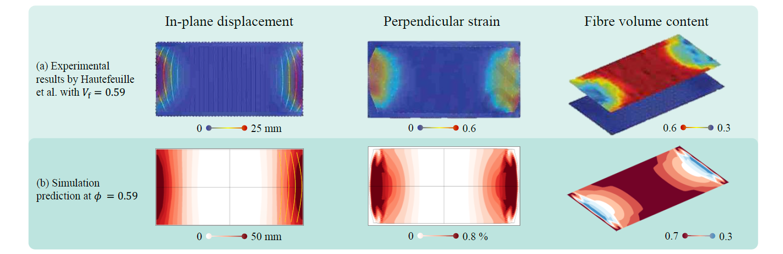
Fig. 5. Qualitative comparison | (a) Experimental results by Hautefeuille et al. [13] for flow-induced fiber displacement during viscous compaction for an unidirectional reinforced composite; (b) Numerical prediction using the outlined modelling approach and UD-NCF material
5 Conclusion
To enable a numerical prediction of flow-induced fiber deformation during viscous compaction, a strong fluid-structure-interaction (FSI) between fluid pressure and fabric deformation is introduced to an existing modelling approach for WCM process simulation. Dry and viscous compaction trials are conducted in order to parametrize and verify the proposed model. Subsequently, a parametric study with a full impregnated strip illustrated the relevance of frictional conditions within the mold. Moreover, two types of flow-inducted deformation should be distinguished. Under low frictional conditions, deformation starts imminently and progresses along with the flow direction, whereas increased friction leads to an inverse effect, which means that deformation starts localized at the vent and progresses inward. Finally, the proposed model is successfully applied to qualitative prediction of in-plane displacement, strain and fiber volume content in comparison with an experimental study.
Future work will focus on a suitable contact modelling including the differentiation between dry and wet surfaces according to the current flow front progression. Moreover, the presented approach needs to be quantitatively verified by experimental results conduced with the same material. In this manner, a sufficient approach to deal with superficial fluid is pursued. Besides, a proper investigation of multi-ply stacks and more complex geometries is needed to evaluate the full potential of the proposed modelling approach.
Acknowledgements
The authors would like to thank the German Federal Ministry of Education and Research (BMBF) for funding of project HyWet as part of the Transatlantic cluster for Lightweighting (TraCLight), for which this work has been carried out. Furthermore, the authors thank the German State Ministry for Science, Research and Art (MWK) of Baden-Württemberg for the project and Forschungsbrücke Karlsruhe-Stuttgart, in which essential preliminary work has been conducted. The work is also part of the Young Investigator Group (YIG) Tailored Composite Materials for Lightweight Vehicles, gratefully funded by the Vector Stiftung.
