1 Introduction
Lightweighting is a development strategy that aims to increase a system’s efficiency and to decrease CO2 emissions rather than just reducing the weight of a system. Continuously fibre-reinforced composites made of engineering textiles like woven or non-crimp fabrics, provide a particularly high lightweight potential and have the advantage to be tailor-made for the specific application [4]. However, a detailed understanding of the manufacturing process is necessary to fully exploit this potential. Therefore, finite element (FE) forming simulations can be used to analyse the deformation behaviour and to predict effects like fibre orientation or wrinkling.
State of the art forming simulation approaches mainly apply conventional two-dimensional shell approaches [5] to efficiently model the deformation of thin fibrous reinforcements, since they allow for high aspect ratios while still accurately describing the membrane and bending behaviour. However, those approaches cannot model out-of-plane compaction, which is an important forming mechanism to predict local fibre volume contents [6] and influences the permeability of the reinforcement during processes such as wet compressions moulding [7,8]. To predict these effects and the final thickness of the part, a three-dimensional FE-formulation is necessary.
The problem with utilizing most commercially available solid elements for composite forming simulations is the occurrence of numerical locking phenomena, which cause a too high bending stiffness and significantly influence the forming behaviour especially for high aspect ratios [1]. Therefore, so-called solid-shell elements have been developed, which combine techniques like reduced-integration and modifications to the strain field to alleviate geometric and material locking phenomena [9]. In the context of forming simulations, solid-shell elements have been successfully applied to sheet metal forming [10, 11], packaging simulation of cardboard [12] and recently composite forming [13]. Thereby, the prismatic solid-shell element developed by Xiong et al. [13] for thermoforming of thermoplastic prepregs utilizes an additional degree of freedom at the element centre for an improved calculation of transverse normal stresses, in combination with a discrete Kirchhoff assumption for zero transverse shear strains.
Additionally, engineering textiles have a specific forming behaviour, which requires a membrane-bending decoupling to describe their deformation behaviour. Three-dimensional element formulations based on the classical continuum mechanics of Cauchy are not capable of modelling very low stiffness under bending, while simultaneously considering a high in-plane membrane stiffness. Therefore, methods based on generalized continuum mechanics can be utilized. Those so-called second-order gradient approaches require elements with high-order interpolation functions, which are numerically expensive and difficult to implement in a commercial solver [14]. As an alternative, approaches introducing a bending stiffness based on a curvature calculation with neighbouring elements have shown promising results for thick 3D woven reinforcements [15].
In the present study, the 3D hexahedral solid-shell element with only translational degrees of freedom initially proposed by Schwarze and Reese [2, 3] and extended to an explicit formulation by Pagani et. al. [16] is used. The selected element formulation is implemented as user-element (VUEL) in ABAQUS/Explicit. To ensure computational efficiency, a MATHEMATICA-based programming environment called ACEGEN [17] is used. ACEGEN provides a symbolic implementation and differentiation combined with a simultaneous runtime-optimization. This work presents a continuation of the investigations performed for the isotropic case in Schäfer et al. [1]. It extends the approach for the forming of highly anisotropic materials and introduces modifications to the hourglass stabilization to account for the anisotropy in the stabilization. The potential of this solid-shell element for the macroscopic forming simulation of engineering textiles is shown by comparison to commercially available shell and solid elements during multiple hemisphere forming tests. Furthermore, an approach for the membrane-bending decoupling within the linear 3D element formulation is proposed. It is based on a Taylor approximation of the strain with respect to the out-of-plane direction and does not require to consider the displacements of neighbouring elements. The potential of this decoupling method is shown by application to numerical coupon and component forming tests.
2 Solid-shell element
The investigated solid-shell element is derived from a standard isoparametric 8-node hexahedral brick-element with tri-linear shape functions. The details of the element formulation can be found in Schwarze & Reese [2, 3], as well as the extensions necessary for an explicit formulation in Pagani et. al. [16]. This section only highlights some of the main aspects of the solid-shell element relevant for a geometric and volumetric locking-free bending behaviour, which is necessary to accurately and efficiently describe the forming behaviour of thin structures with high aspect ratios [1].
The element uses a reduced integration scheme with a single integration point in the shell plane and a variable number of integration points (at least 2) along the normal through the element centre defined in isoparametric coordinates by 𝝃*={0, 0, 𝜁}⊤. This integration scheme was shown to be computationally efficient [16] and captures non-linearities in the thickness direction for thin structures very well, compared to commercially available explicit reduced-integration elements which mostly use a single integration point in the element's centre.
The total Green-Lagrange strain tensor 𝑬 is additively split (𝑬=𝑬c+𝑬e) according to the enhanced assumed strain (EAS) concept based on the Hu–Washizu variational principle into a compatible part 𝑬c(𝒖), depending solely on the displacement vector 𝒖, and an enhanced part 𝑬e(𝑤e), depending on a single additional enhanced degree of freedom 𝑤e, which is utilized to prevent volumetric and Poisson thickness locking. The transverse shear and curvature thickness locking are cured through the assumed natural strain (ANS) method for the transverse shear and normal components of the covariant compatible Green-Lagrange strain. Another key aspect of the element is a Taylor approximation of the compatible strain with respect to element centre 𝝃=𝟎:

where the derivatives Ê𝒄(•) are constant tensors. This allows for a separation into a strain part related to the out-of-plane integration Êc* and a part unused by the numerical integration Êchg, which is essential to the hourglass stabilization of the reduced integration scheme. Similarly, a Taylor approximation of the second Piola-Kirchhoff stress along the out-of-plane direction 𝝃* is carried out:

where again the stress is separated into the parts related to the out-of-plane integration and hourglass stabilization. The complexity of the hourglass stabilization part is reduced by replacing the in general material- and deformation-dependent tangent 𝜕𝑺̂/𝜕Ê|𝝃=𝝃* with a constant hourglass stiffness matrix ℂ̂hg. This method allows for efficient analytical integration of the hourglassing terms while maintaining a full rank of the element formulation. For the description of the material behaviour, a Saint Venant-Kirchhoff hyperelastic approach [18] is used, which leads to:

Adaptations for forming simulations of engineering textiles
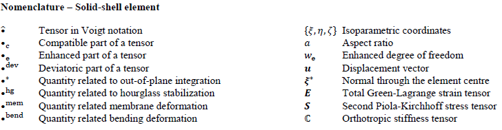
The above described solid-shell element has shown very promising results compared to commercially available elements in ABAQUS/Explicit for the forming simulation of thin structures with high aspect ratios in an isotropic case [1]. In the next step, the formulation is tested for highly anisotropic materials, to emulate the deformation behaviour of engineering textiles. Therefore, two different orthotropic stiffness matrices with high stiffness in one (ℂ̂UD) or two (ℂ̂Biax) principal material directions and low shear and compaction stiffnesses for both cases are chosen for this investigation. A relatively low stiffness of 1000 MPa in the principal material directions is chosen to reduce the explicit time increment in this comparative study, while maintaining a large anisotropy ratio and therefore limiting the in-plane strains in fibre direction:
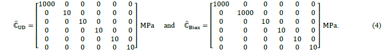
The application to model a single-layer hemisphere forming test leads to hourglassing instabilities on the edges during the initial contact of the fabric and tool, cf. Figure 1. The location of these effects agrees with observations from single element tests with as few Dirichlet boundary conditions as possible, where the most critical deformation for provoking instabilities is compaction in the thickness direction.
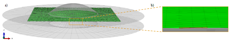
Fig. 1. (a) Single-layer hemisphere test with (b) a detail view of the occurring hourglassing modes along the edge of the fabric and the typical hourglass shape highlighted in red, occurring with unadjusted stabilization
Modified hourglass stabilization. In the work of Schwarze & Reese [2, 3], the hourglass stiffness matrix was approximated by a constant deviatoric matrix ℂ̂hg=𝜇effhg 𝕀̂dev based on an effective shear modulus 𝜇effhg and the deviatoric part of the fourth-order identity tensor 𝕀̂dev. A deviatoric hourglassing stiffness was chosen to ensure a volumetric locking-free stabilization, according to the B-Bar method developed by Hughes [19]. This approximation leads to an underestimation of the hourglassing stress for highly anisotropic materials because the calculated isotropic effective shear modulus is significantly too low. Therefore, the hourglassing stiffness matrix is replaced within this study by the material tangent evaluated in the element centre through:

which accounts for the anisotropy in the stabilization, while still allowing for an analytical integration of the hourglassing terms. However, this approach does not conform with the B-bar method and is therefore limited to compressible materials to prevent volumetric locking.
The construction of a suitable anisotropic hourglass stiffness, which prevents volumetric locking, would require further investigations and is not part of this work, because the intuitive approach to only use the deviatoric part of the anisotropic stiffness ℂ̂hgdev= 𝕀̂dev:ℂ̂hg could lead to non-symmetric stiffness matrices and therefore potentially resulting in non-physical negative hourglassing energies. However, since the focus of this work are engineering textiles, which are compressible in most cases, and the choice for the hourglassing stiffness according to Equation 5 shows promising results, the influence of a possible volumetric locking in the hourglassing terms is assumed to be small.
Membrane-bending decoupling. To describe the forming behaviour of engineering textiles, a decoupling of the in-plane (membrane) and out-of-plane (bending) behaviour is often introduced in approaches based on conventional shell elements. Based on this idea and in combination with the Taylor approximations of the strains in Equations 1, the following split is introduced to the stress 𝑺̂* by:

where the membrane part 𝑺̂mem is related to the constant compatible strain in the element centre Êc0 by a membrane stiffness matrix ℂ̂mem, while the bending part 𝑺̂bend is related to the out-of-plane components of the compatible strain Êc𝜁 and Êc𝜁𝜁 as well as the enhanced strains Êe* by a bending stiffness matrix ℂ̂bend.
3 Numerical studies
To investigate the potential of the solid-shell element formulation outlined in Section 2 for forming simulations of engineering textiles, two different numerical studies are shown in the following section. First, the advantages of a geometric and volumetric locking-free forming behaviour of the solid-shell element for highly anisotropic materials are presented through a comparison to in ABAQUS/Explicit commercially available shell and solid elements in a single layer hemisphere test. Similar to our previous study [1], where the significant influence of the element formulation on the forming behaviour even for a simple linear isotropic material model was shown. Secondly, it is demonstrated by a simple tensile and cantilever-bending test that the approach proposed in Equation 6 can be utilized for a membrane-bending-decoupling, and initial results for its influence on the forming behaviour are shown.
3.1 Hemisphere test for highly anisotropic material
To focus on the influence of the element formulation on the forming behaviour as best as possible, a single layer with a thickness of 𝑡=0.3 mm is used in multiple hemisphere tests with a total tool stroke of 35 mm, cf. Figure 1 a). The tests are performed with an orthotropic material law, for both stiffness matrices ℂ̂UD and ℂ̂Biax, cf. Equation 4, as well as aspect ratios (𝑎=𝑙e/𝑡) of 𝑎1=10 and 𝑎2=20. The solid-shell element without the membrane-bending decoupling is compared to in ABAQUS/Explicit commercially available reduced integrated shell (S4R) and solid (C3D8R) elements, as well as a fully integrated solid element (C3D8), a reduced integrated solid element with an enhanced hourglass stabilization based on the EAS method (C3D8R-Enh) and a fully integrated element with incompatible modes (C3D8I).
Figure 2 shows the results for a remaining tool stroke of Δ𝑢=7.0 mm because at this stage the differences in the forming behaviour can be better highlighted than for a completely closed tool. The wrinkling development in terms of size and pattern is strongly influenced by the different element types, whereas the elements known to behave too stiff under bending deformation tend to have larger wrinkles form. These results agree with the observations made in literature [20-23].
Based on the assumption that the reduced integrated shell element (S4R) is locking-free even for large the aspect ratios [1, 24], it is used as a desired reference solution in this study. For a biaxial stiffness ℂ̂Biax and both 𝑎1 as well as 𝑎2, it shows a consistent forming behaviour with medium-sized wrinkles developed in all directions. For a unidirectional stiffness ℂ̂UD the results are again similar for both investigated aspect ratios, with the developed wrinkles mainly oriented along the axis of the highest stiffness and semi-circular runouts towards the edges. The only element that can achieve a forming behaviour similar to the shell for all tests is the solid-shell element presented in Section 2. However, looking into more detail some individual elements in the area of radius shows a slight hourglassing shortly before the tools are completely close even though it seems not to influence the global forming behaviour. This indicates that the proposed approach for the hourglass stiffness, cf. Equation 5, still needs improvements in areas of large compactions.
The deformation behaviour of the reduced integrated solid element (C3D8R) is completely different compared to all other examined elements. The orientation of the onset of wrinkles is only perpendicular to the edges of the thin sheet and they are larger compared to the reference solution. While introducing an enhanced hourglassing stabilization (C3D8R-Enh) to alleviate locking-effects showed very promising results in the previous study for isotropic material [1], the behaviour for highly anisotropic materials is significantly different with an unexpected orientation of the development of wrinkles in the y-direction for a unidirectional (highest stiffness in the x-direction) as well as a biaxial stiffness.
Fig. 2. Hemisphere test | Results for a remaining tool stroke 𝛥𝑢 of 7.0 mm for the proposed solid-shell element compared to a conventional shell (S4R) and different conventional solid (C3D8R-Enh, C3D8I, C3D8R, C3D8) elements with different aspect ratios of 𝑎∈{10 ,20} and stiffness matrices ℂ̂∈{ℂ̂Biax, ℂ̂UD} with coloured indicators to rate their forming behaviour (green ≙ good agreement with S4R; yellow ≙ slightly too stiff behaviour; red ≙ forming behaviour significantly different to S4R)
The results of the fully integrated solid element (C3D8) in the biaxial case for a smaller aspect ratio 𝑎1 are in good agreement with the chosen reference. An increase in size and decrease in the number of wrinkles is observed for the larger aspect ratio 𝑎2, which could also be seen for the isotropic case and is expected due to its known too stiff behaviour in bending situations due to locking phenomena [1]. However, in the unidirectional case, the orientation of the onset of wrinkles is slightly different and the size is increased, which again indicates a too high bending stiffness. The fully integrated solid element C3D8I is enhanced by incompatible modes to prevent parasitic locking stresses in bending deformations [22]. Thus, it shows a forming behaviour very similar to the shell element for a smaller aspect ratio 𝑎1 and only slightly too stiff for 𝑎2.
The hemisphere tests show that the element formulation and thus locking-free bending behaviour for larger aspect ratios have a significant influence on the macroscopic forming behaviour, even for a simple linear orthotropic material model. The solid-shell element, cf. Section 2, is the only element which consistently has a similar forming behaviour compared to the chosen reference shell element (S4R) for large aspect and anisotropy ratios.
3.2 Membrane-bending decoupling
Proof of concept. To test whether the membrane-bending decoupling based on the approach proposed in Equation 6 works, simple tensile and cantilever-bending tests are performed. The geometry and load conditions are shown in Figure 3. In both tests, the beam is discretized by one element in the thickness and 10 elements in the length direction, which yields an aspect ratio of 𝑎=20. Both tests are performed with a total of four different combinations of a higher and lower membrane as well as bending stiffness each. Thereby, the higher bending and membrane stiffnesses are chosen equal to Equation 4 with ℂ̂UDmem=ℂ̂UDbend=ℂ̂UD and the lower stiffnesses differ from the higher stiffnesses only in the 11-component by (ĈUDmemlow)11=(ĈUDbendlow)11=1/10⋅(ĈUD)11=100 MPa.
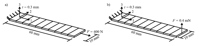
Fig. 3. a) Tensile test| geometry and load; b) Cantilever-bending test| geometry and load
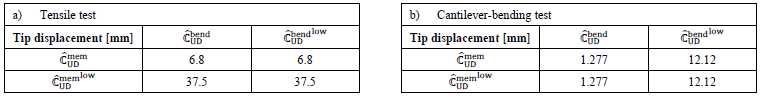
The results of the tensile and cantilever-bending tests are shown in Table 1 (a) and (b) respectively. As expected, the tip displacement in the tensile test is only increased by decreasing the membrane stiffness and independent of the chosen bending stiffness. Analogously, this behaviour is shown for the cantilever-bending test with a decrease of the bending stiffness. This indicates that the proposed approach for a membrane-bending-decoupling in Equation 6 works.
Table 1. Resulting tip displacement for (a) the tensile test and (b) the cantilever-bending tests
Influence on the forming behaviour. The proposed membrane-bending decoupling is applied to single-layer hemisphere tests, cf. Figure 1 a), with 𝑎=20 and constant unidirectional ℂ̂UDmem=ℂ̂UD and biaxial ℂ̂Biaxmem=ℂ̂Biax membrane stiffnesses. The bending stiffness is initially equal to the respective membrane stiffness (ℂ̂UDbend=ℂ̂UDmem & ℂ̂Biaxbend=ℂ̂Biaxmem) and then the 11-component in the unidirectional, as well as additionally the 22-component in the biaxial case, is either increased (ℂ̂UDbendhigh& ℂ̂Biaxbendhigh) or decreased (ℂ̂UDbendlow& ℂ̂Biaxbendlow) by a factor 10. The results for different remaining tool strokes Δ𝑢 are shown in Figure 4.
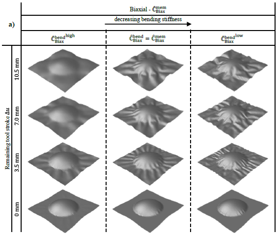
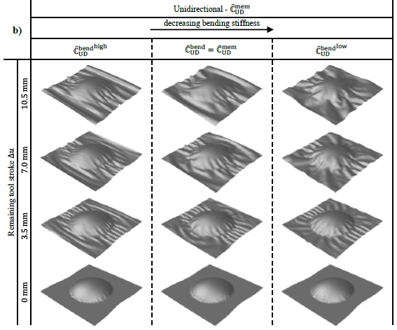
Fig. 4. Hemisphere test | Results for a constant a) biaxial and b) unidirectional membrane stiffness with different bending stiffnesses at several remaining tool strokes 𝛥𝑢
In the biaxial case, decreasing the bending stiffness leads to the onset of smaller wrinkles and an increase in their number, while their general orientation, as well as location, stays the same. A higher bending stiffness in the unidirectional case leads to a straightening of the wrinkles located towards the edges, while for a lower bending stiffness more wrinkles perpendicular to the x-axis are forming. These results agree with the observations made in the literature [20-23].
4 Conclusion and outlook
A linear solid-shell element suitable for the forming simulations of highly anisotropic materials with a membrane-bending decoupling based on a Tailor expansion of the strain is presented. The advantages of its locking-free bending behaviour in forming simulations are shown by comparison to commercially available shell and solid elements. The forming results are consistent for large aspect ratios and in agreement with a typical shell element, outperforming all investigated commercially available solid elements that either behave significantly different or too stiff due to locking phenomena. The proposed approach can show typical characteristics of the membrane-bending interdependency in coupon tests as well as in forming simulations. The shape, size and orientation of wrinkles depend on the ratio between the membrane and bending stiffness.
These are necessary prerequisites to model the deformation of thin engineering textiles efficiently in macroscopic forming simulations. However, so far only linear-elastic orthotropic materials are investigated. In future studies, the material model will be adapted to the in general non-linear behaviour of different deformation modes of an engineering textile and validated with experimental test. In this context, especially the proposed calculation of the hourglassing stiffness needs to be re-evaluated, since during the numerical studies some slight hourglassing occurred in areas of higher compaction.
The utilized solid-shell element formulation is known to be geometric and volumetric locking-free for isotropic and slightly anisotropic materials [1-3]. However, the potential occurrence of a locking phenomenon specific to engineering textiles known as intra-ply shear [25] or tension [26] locking needs to be investigated. In this study, the impact of this locking phenomenon is assumed to be small, since the principal material directions are aligned with the mesh orientation. This alignment is not always possible for arbitrary shaped textiles and may require further modifications to the hourglass stabilization to alleviate tension locking [26].
Furthermore, the benefits of modelling the thickness direction will be investigated in the context of composite forming. Since the state of the art forming approaches are mainly based on shell elements and therefore often limited in the consideration of the out-of-plane behaviour. The utilization of a fully three-dimensional approach should enable a better approximation of forming effects like local thickness changes and fibre volume content [6], by investigating the compaction behaviour.
Acknowledgements
The authors would like to thank the Deutsche Forschungsgemeinschaft (DFG, German Research Foundation) and the French National Research Agency (ANR) for funding the collaborative project “Composite forming simulation for non-crimp fabrics based on generalized continuum approaches” (project number 431354059), which the presented work is carried out for. The work is also part of the Young Investigator Group (YIG) “Tailored Composite Materials for Lightweight Vehicles”, generously funded by the Vector Stiftung.
