1 Introduction
Lightweighting is an important enabler in the modern automotive industry for reducing greenhouse gas emissions and achieving future regulations [1]. For this purpose, continuously fiber-reinforced composites offer great potential due to their excellent mechanical properties and low density. However, their capability to be shaped into complex geometries is limited. In contrast, chopped fiber materials reveal the potential to be used for more complex geometries, including local thickness changes, ribs, and beads, offering significant potential for functional lightweighting [2,3].
With an eye towards the developments within Industry 4.0, a continuous and functional virtual process chain is a powerful tool. Thereby, a digital twin of the manufacturing process using process simulation is suitable for optimization of the manufacturing process. In the context of a continuous virtual process chain, a digital twin enables the robust development and virtual testing of new components or the adjustment of components due to changes in boundary conditions or requirements [2].
The material investigated within this study is Tepex flowcore, a long glass fiber reinforced polyamide (PA/GF) glass mat manufactured by Lanxess, Bond Laminates. This material is characterized by high fiber volume content (47 vol.%), random fiber orientation, and consistent fiber length distribution. Tepex flowcore consists of long (30-50mm) glass fibers with an engineering polymer, i.e. PA6, and belongs to the material class of Glass Mat Thermoplastic (GMT). Foremost, the material is processed using thin blanks and high initial mold coverages, resulting in comparably short flow paths to obtain the final part thickness. Nonetheless, a squeeze flow of the material cannot be excluded in general. Based on this, the processing of Tepex flowcore can in general be subdivided into two sequential stages: Thermoforming and squeeze flow (cf. Figure 1). Thermoforming can include typical defects such as local wrinkling. In contrast, squeeze flow is described by a distinct material flow.
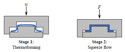
Fig. 1. Schematic illustration of the stages during the processing of Tepex flowcore for high initial mold coverages
Regarding process simulation, thermoforming simulation explicitly aims to predict the forming behavior in terms of in- and out-of-plane deformations, such as shearing, elongation, or bending, as well as local defects such as wrinkling. Recent studies focus on continuously fiber-reinforced thermoplastic tape laminates [4-7], using purely Lagrangian approaches. In this context, most of the existing approaches utilize conventional shell elements, due to the high slenderness ratio of the related pre-products. Only a few studies consider three-dimensional approaches thus far since these materials often reveal a specific material behavior under bending loading, which cannot be captured directly by first-order three-dimensional material modeling approaches [8]. Our previous study [9] demonstrated that existing thermoforming simulation approaches are applicable to predict the thermoforming behavior of Tepex flowcore. Additionally, it is shown that the decoupling of membrane and bending behavior is not strictly necessary. Therefore, first-order three-dimensional modeling approaches become applicable to this material class.
For the prediction of squeeze flow in compression molding simulation, approaches that apply two-phase methods based on Darcy's law [10] or separate fiber and matrix speeds with a model transition for different flow regimes [11] have been developed. Direct fiber bundle simulations [12] are another two-phase method that enables detailed studies on fiber orientation, e.g. at rib geometries [13]. However, the majority of compression molding simulation approaches consider the material as a single-phase using Eulerian or Arbitrary Lagrangian Eulerian (ALE) modeling approaches. In recent publications [2,14,15], Sheet Molding Compound (SMC), also a chopped fiber material with a thermoset matrix, is modeled as a three dimensional, single-phase, weakly compressible, anisotropic, non-Newtonian material that experiences slip at the mold surface using a Coupled-Eulerian-Lagrangian (CEL) approach. A similar approach is conceivable for squeeze flow simulation of GMT materials since these approaches are capable to predict the material flow of highly filled fiber suspensions.
Currently available process simulation approaches for GMT materials, however, typically include either a thermoforming simulation or a squeeze flow simulation, not both. One recent study [16] applied a sequential approach with two separate and sequential simulations in which thermoforming was modelled in LsDyna using a Lagrangian approach and the results were then transferred into a squeeze flow simulation in Moldex3D. However, the two simulations required separate material characterizations and material models, with a limited carryover of information from one simulation to the next (namely temperature and shape). To accurately simulate molding of GMT materials, both sequential simulation of thermoforming and squeeze flow, as well as an accurate, unified, and continuous representation of the material behavior and its state are required.
In this study, these two challenges are addressed and a unified approach to model the molding process in a continuous fashion is presented. First, thermoforming is modeled through a first-order three-dimensional thermoforming simulation using a Lagrangian approach. Subsequently, relevant material state variables are transferred as initial conditions to a squeeze flow simulation, which uses a CEL approach. The state variables are mapped from the Lagrangian to the Eulerian mesh using in-house import/export scripts for ABAQUS/CAE and the MpCCI Mapper, which is developed by Fraunhofer SCAI and supplied by scapos AG. Both process simulation stages use a fully-coupled thermomechanical analysis and the same constitutive equations to predict the mechanical behavior, namely the thermoforming and squeeze flow behavior, as a function of temperature and crystallization kinetics. For this purpose, existing approaches for the commercially available simulation software package ABAQUS/Explicit based on user-subroutines for thermoforming simulation [4,5,9] and SMC compression molding simulation [2,14,15] have been combined and further developed.
2 Modeling approaches
The proposed sequential process simulation approach for GMT materials and in particular for Tepex flowcore consists of two simulation steps using the commercially available simulation software package ABAQUS/Explicit in combination with a material user-subroutine (VUMAT). These simulation steps predict thermoforming and squeeze flow (cf. Figure 2). While the numerical techniques are different, both steps use the same constitutive equations, respective user-subroutine, as well as the same tool kinematics modeling approach. Therefore, the adopted constitutive equations (cf. Section 2.1) and tool kinematics modeling approach (cf. Section 2.2) are outlined initially. Subsequently, the specificities of the thermoforming simulation (cf. Section 2.2), the mapping procedure (cf. Section 2.3), and the squeeze flow simulation (cf. Section 2.4) are outlined.
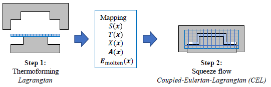
Fig. 2. Schematic illustration of the sequential steps for process simulation of GMT materials
2.1 Constitutive equations
Thermal modeling. The governing equation for thermal modeling is the heat balance equation in combination with the generalized Fourier’s equation, which is given in the weak form by:

where 𝑇 is the temperature, 𝜌 the material density, 𝑐𝑝 the heat capacity, 𝛌 the heat conductivity tensor, 𝑠 a surface flux on the boundary, and 𝑟 a heat flux source term. The surface flux 𝑠 splits into two terms to account for convection and radiation (𝑠 = 𝑠conv + 𝑠rad) and the source term 𝑟 is applied to account for the latent heat due to crystallization (𝑟 = 𝜌Δℎcryst𝑋̇), where Δℎcryst is the specific crystallization enthalpy. The relative crystallinity 𝑋 is predicted by Nakamura’s equation, which is given in the differential form by [17]:

Based on the Avrami index 𝑛 and the crystallization rate constant 𝐾, for which Ziabicki’s empirical approach [18] is adopted:

Through the determination of the material parameters 𝐾max, 𝑇max, and 𝐷 for each cooling rate considered in Differential Scanning Calorimetry (DSC), crystallization kinetics becomes predictable over a wide range of cooling rates. Based on this, the transition from the molten (𝑋=0) to the solid material state (𝑋=1) is predicted and considered in process simulation.
Thermomechanical coupling. The total stress upon deformation is expressed in terms of the Cauchy stress 𝝈 separately for the molten and the solid material state as a function of the temperature 𝑇 and the relative crystallinity 𝑋 through:

Thus, both the temperature-dependency of mechanical behavior in the molten material state and the transition from the molten to the solid material state are considered in mechanical modeling. Thereby, the superpositioning of both stress states via the relative crystallinity 𝑋 guarantees a smooth transition from the molten to the solid material state.
Molten material state. In the molten material state, the Cauchy stress is determined through:

where 𝑝 is the hydrostatic pressure derived from an equation of state (EOS) and 𝛔visc denotes the viscous stress. The EOS models the compressibility through the two-domain Tait-model [19] reformulated for the molten regime by:

where 𝑏3molten, 𝑏4molten, and 𝑏5 are material parameters. The viscous stress is computed through:

where 𝑫′ is the deviatoric rate of deformation tensor, which can be determined from the velocity gradient 𝑳 (𝑫′=dev(sym(𝑳))). The viscosity 𝜂 is defined as a function of temperature 𝑇 and equivalent shear-rate (𝛾̇=√2𝑫:𝑫) following a Cross-WLF approach [20]:

Solid material state. The solid material state is modeled through a St. Venant-Kirchhoff hyperelastic approach [21]:

where 𝐽 is the Jacobian, 𝑭 is the deformation gradient, 𝑺 the second Piola-Kirchhoff stress, ℂ an orthotropic stiffness tensor, E the Green-Lagrange strain, and 𝐅molten the deformation gradient at the onset of crystallization, being the reference configuration for the constitutive equations in the solid material state. This configuration is obtained through a multiplicative decomposition of the deformation gradient (𝑭=𝑭solid⋅𝑭molten), yielding an additive split of the Green-Lagrange strain (E = Esolid+ Emolten).
Fiber orientation. The evolution of fiber orientation due to material deformation and material flow is modeled through the second-order fiber orientation tensor following Jeffery’s equation [22]. Based on this, the need to characterize numerous fitting parameters, as needed for other fiber orientation models, such as the ARD-RSC model [23], is circumvented. Using the vorticity tensor (𝝎=skw(𝑳)) and 𝜆=1 for long slender fibers, the tensorial form of Jefferey’s equations:

as proposed by Advani and Tucker [24], is adopted. Here, 𝔸 is the fourth-order fiber orientation tensor that is computed using the invariant based optimal fitting (IBOF) closure [25].
2.2 Tool discretization and kinematics
The tools are modeled by discrete rigid elements in both thermoforming and squeeze flow simulation, which is enabled through the purely Lagrangian and the Coupled-Eulerian-Lagrangian (CEL) approaches, respectively. The tool kinematics is modeled in real-time, to accurately account for temperature and rate-dependent effects. A scaling of time for numerical efficiency is conceivable but is not straightforward due to the nonlinear nature of the constitutive equations described in the previous section. Therefore, mass scaling for improving numerical efficiency is preferred. Regarding boundary conditions, a purely displacement-controlled press profile and a constant and homogeneous temperature is assigned to the tools in the scope of this study.
2.3 Thermoforming simulation
Thermoforming simulation is conducted with a purely Lagrangian and fully coupled thermomechanical approach with explicit time integration due to large contact areas. Solid elements are used for the discretization of the blank, to take into account the three-dimensional deformation behavior. Hexagonal elements with incompatible modes (C3D8I) are adopted, to prevent numerical locking effects of the elements with a high slenderness ratio under bending loading. Since no thermomechanical hexagonal elements with incompatible modes are available in ABAQUS, thermal behavior is modeled through superpositioned thermomechanical hexagonal elements with reduced integration (C3D8RT). The material user-subroutine (VUMAT) including the constitutive equations described in Section 2.1 is assigned to the C3D8I elements. In contrast, quasi-zero stiffness, as well as heat capacity and heat conductivity, are assigned to the C3D8RT elements.
2.4 Mapping
The transition from thermoforming to squeeze flow simulation requires the transfer of relevant state variables between two different simulation approaches and meshes (cf. Figure 2). Besides the material volume fraction S at the position x, describing the initial charge for squeeze flow simulation, the temperature 𝑇, the relative crystallinity 𝑋, the second-order fiber orientation tensor A, as well as the strain in the molten material state Emolten are transferred as state variables and considered as initial local conditions. This transfer requires a mapping of the aforementioned state variables from the Lagrangian mesh of thermoforming simulation on the Eulerian mesh from the CEL approach for squeeze flow simulation. The mapping is enabled through in-house import/export scripts for ABAQUS/CAE using the neutral ASCII-format vtk. Based on this, the source and target data stored in vtk files are adopted and the mapping itself is conducted with the MpCCI Mapper, which is developed by Fraunhofer SCAI and supplied by scapos AG. Using these tools, the elemental state variables are mapped using a weighted element technique.
2.5 Squeeze flow simulation
Squeeze flow is modeled utilizing the ABAQUS/Explicit Coupled-Eulerian-Lagrangian (CEL) approach, which is based on the work of Benson [26,27]. The fundamental idea of this approach is to apply an operator split with a Lagrangian step and a subsequent Eulerian transport step. The Eulerian step is computed by moving the deformed nodes back to their fixed positions and calculating the volume of material transported between neighboring elements [27]. State variables are advected assuming a linear interpolation in each element of the deformed configuration and mapping them to the adjusted configuration based on the volume material fractions. Based on this, the cavity is discretized using Eulerian elements (EC3D8RT) and the mapped state variables describe the initial charge through the volume fraction S(x) and its state through additional state variables (cf. Figure 2).
3 Application example
3.1 Model setup
The hat section geometry presented in Figure 3 is adopted as an application example. For this purpose, a 4 mm blank with the dimensions 950 x 335 mm² is used. A tool temperature of 150 °C and an initial blank temperature of 287.3 °C, which is the expected temperature after heating the blank to 300 °C and transferring it to the mold, is assigned. In the thermoforming simulation, a gravity step is followed by a displacement-controlled press profile with a decrease of press velocity towards mold closure. In contrast, a constant press velocity is used for squeeze flow simulation. The whole cycle amounts to 8.9 s.
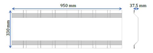
Fig. 3. CAD and dimensions of the part (hat section geometry) investigated in the scope of this study
3.2 Thermoforming simulation results
Figure 4 is a sequence of results for the temperature distribution in thermoforming simulation, including the gravity step of 6.0 s, in which the blank is dropped on the lower tool, as well as 2.0 s of thermoforming with moderate deformation until the mold gap reaches the initial blank thickness. The thermoforming stage is accompanied by significant temperature changes at the lower surface and moderate temperature changes at the top surface induced by the longer time of tool-ply contact at the bottom surface. Based on this, a significant temperature gradient is rendered onto the blank already in the thermoforming stage (cf. Figure 5).
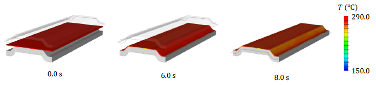
Fig. 4. A sequence of results for the temperature distribution in thermoforming simulation

Fig. 5. Detailed view temperature distribution in thermoforming simulation at 8.0 s
3.3 Squeeze flow simulation results
Figures 6 and 7 present a sequence of simulation results of the temperature distribution for the squeeze flow stage. It is observed that the CEL approach is capable of predicting material flow and the filling of the mold. For this application example, a flow length of approximately 10.0 mm is required to fill the mold. Mold filling along with significant temperature changes at all surfaces is observed. Finally, temperatures close to the tool temperature are observed at the top flanges and lower surfaces. The detailed view in Figure 7 reveals that heat loss is mainly restricted to the blank surfaces, whereas the core remains significantly hotter.
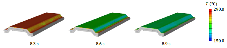
Fig. 6. A sequence of results for the temperature distribution in squeeze flow simulation
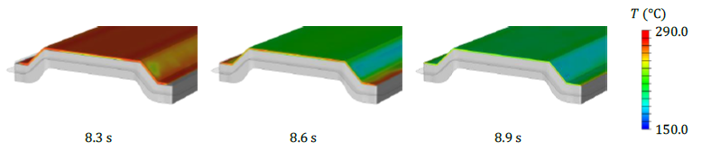
Fig. 7. Detailed view of results for the temperature distribution in squeeze flow simulation
The material is mostly in the molten material state (𝑋 ≤ 0.15) throughout thermoforming and squeeze flow (cf. Figure 8). However, the onset of recrystallization is observed, revealing the importance of considering crystallization kinetics for process simulation, since severe recrystallization and thus solidification already during processing might occur for a slower press profile. Also, some minor unfilled areas along the longitudinal part edges are predicted (cf. Figure 8). Here, it should be noted that the modeled press profile is fully displacement-controlled. Usually, the press switches from a displacement- to a force-control as soon as a prescribed maximum force is reached. This is not considered so far in simulation and might influence the predicted squeeze flow.
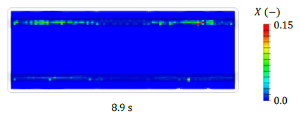
Fig. 8. Relative crystallinity at the end of squeeze flow (top view)
4 Conclusion and outlook
A sequential approach for process simulation of glass mat thermoplastics using the commercially available software package ABAQUS/Explicit in combination with user-subroutines is presented. The proposed approach consists of two sequential steps, namely thermoforming and squeeze flow simulation. Both approaches use the same three-dimensional, thermomechanical constitutive equations implemented in a material user-subroutine (VUMAT), including an equation of state, a non-linear shear-viscosity model, and a crystallization kinetics model. However, different numerical techniques are adopted. The thermoforming step uses a Lagrangian modeling approach to efficiently capture the forming behavior. In contrast, the squeeze flow step uses a Coupled-Eulerian-Lagrangian (CEL) approach, to appropriately capture material (squeeze) flow.
The proposed approach is successfully applied to a hat section geometry and Tepex flowcore, including a gravity step, thermoforming, and squeeze flow simulation. It is observed that the heat loss due to tool-ply contact renders a significant temperature gradient onto the blank. Temperatures close to the tool temperature are observed at the blank surfaces, whereas the core remains comparably hot. Also, the onset of recrystallization is observed. Therefore, using a thermomechanical approach including modeling of crystallization kinetics is expected to be seminal for process simulation of GMT materials and Tepex flowcore.
For future studies, a substantial step will be the validation of this approach using experimental processing tests. Moreover, the further development of the constitutive equations will be emphasized. This will include anisotropic viscosity modeling, to account for shear- and elongational viscosity separately. Furthermore, the results of the squeeze flow simulation will be transferred to an additional simulation step to predict cooling and process-induced deformations (PIDs) including spring-in and warpage. To obtain a numerically efficient and accurate approach, implicit time integration and a Lagrangian approach will be adopted for this step.
Acknowledgments
The authors acknowledge the funding support of General Motors of Canada, Natural Sciences and Engineering Research Council of Canada (Grant CRDPJ 518279-17), and the Ontario Centres of Excellence (Grant VIP2 28722).
