1 Introduction
Non-crimp fabrics (NCF) provide an exceptionally high lightweight potential due to their straight fibres, compared to undulated fibres in woven fabrics. Among NCFs, unidirectional (UD) NCFs enable a more targeted tailoring than biaxial NCFs. However, their formability is much more challenging in comparison to bidirectional fabrics, and draping effects like shearing, waviness or fibre gapping have a significant impact on the structural performance [1]-[3]. The experimental determination of those effects especially in inner layers of a multi-ply component is challenging and requires dedicated measurement methods [4]. Draping simulations can more easily provide the necessary local information, however need to be suitable and reliable. Mallach et al. [5] conducted optical robot-based measurements of preforming tests to determine shear angles and fibre orientations on the entire surface. They compared the measurements to a macroscopic approach with built-in methods in PAM-FORM and achieved a good prediction of the preform contour and critical regions regarding wrinkling. However, mesoscopic effects like transverse compression, fibre sliding and yarn buckling were not considered in their approach, which led to highly overestimated shear angles as well as large deviations of the fibre orientation.
Macroscopic approaches can predict component forming results efficiently for complexly curved geometries with case-specific process conditions. Due to their better formability, woven fabrics have so far been the focus of research on macroscopic forming models [6]-[8]. In contrast, forming of Biaxial-NCF [9], [10] or even UD-NCF [5], [11]-[14] has been investigated much less and mostly based on mesoscopic approaches, which are not suitable for component forming simulations. In contrast to mesoscopic modelling, macroscopic approaches are not able to discretely predict local forming effects. Nevertheless, they need to capture the relevant forming mechanisms occurring on meso-scale in a homogenized way and consequently indicate areas with a high likelihood of local effects like waviness, transverse compaction or gapping [15]. This desired capability of macroscopic forming simulation of UD-NCF has not yet been addressed in the literature. According to the current state of research and to the authors’ knowledge, the modelling approach proposed by Schirmaier et al. [11] is the most promising macroscopic UD-NCF model available to date. It considers both large-strain deformation and non-linear constitutive behaviour. To account for the permanent deformation caused by irreversible slip between fibre yarns, stitching and glass fibres, an elastic-plastic material model is chosen to capture the experimentally observed non-linearity of the macroscopic stress-strain relation [11], [13], [16].
In previous work, the prediction accuracy of Schirmaier’s model was shown only by qualitative comparison to component forming results [11], without full-field quantitative validation nor evaluation of specific forming effects. Therefore, the model is applied in the present work to forming of an L-shaped geometry in order to quantitatively evaluate the prediction quality regarding global and local forming effects. The results are compared to radiography measurements of internal plies based on the method presented in Kunze et al. [4]. The measurement method allows for the determination of the local deformation, which gives a direct measure not only for fibre orientations, but also for forming effects like gapping, waviness and transverse compression, enabling an estimation, e.g., of the local fibre volume content [17]. Subsequently, the suitability of the macroscopic approach to predict these local effects is evaluated.
2 Macroscopic forming simulation of UD-NCF
The yarns of non-crimp fabrics (NCF) are bonded together by a stitching pattern and glass fibres for handleability. This is in contrast to woven fabrics, which are intrinsically cohesive due to the interwoven fibre yarns. Consequently, the inherent deformation modes of the two types of textiles differ considerably. Woven fabrics deform in pure shear, while shear in UD-NCF can be superimposed by substantial transverse strain [12], [16]. This superposed membrane behaviour needs to be captured by macroscopic material models in a suitable way. In previous work [11], extensive off-axis-tension (OAT) tests have been performed to analyse the multiaxial deformations at meso and macro scale, and to develop a macroscopic material model for the membrane behaviour. This macroscopic model is shortly presented in the following section and is subsequently applied to investigate the prediction of forming effects.
2.1 Non-orthogonal elastic-plastic material model
Macroscopic modelling approaches account for material inhomogeneities in a homogenized way to allow an efficient description of the most relevant deformation mechanisms. The utilized membrane modelling [11] is able to capture large shear strains 𝛾12 superimposed with large non-orthogonal transverse tensile strains 𝜀2 and orthogonal compressive strains 𝜀⊥, cf. Fig. 1(a). Tensile strains 𝜀2 (elongated stitching) and compressive strains 𝜀⊥ (transverse compaction) may occur simultaneously, particularly for large shear strains 𝛾12. The macroscopic approach, however, does not allow for a discrete modelling of the slipping between carbon fibre tows, glass fibres and stitching. Therefore, gapping can only be indicated by large tensile strain 𝜀2 at moderate shear strain 𝛾12 or, more suitably, by large transverse tensile strains 𝜀⊥.
Modelling large non-orthogonal and non-linear deformation of the stitching requires suitable strain and stress measures. For UD-NCF, Schirmaier et al. [11] proposed a formulation for appropriate linear strain and corresponding nominal stress measures. Line segment 𝒕10 represents the material’s first principal direction, oriented in fibre direction. Line segment 𝒕20 corresponds to the direction of the stitching, cf. Fig. 1(b). After deformation, the linear but non-orthogonal strain components 𝜀1 of the fibres and 𝜀2 of the stitching are defined by:

where the line segments 𝒕𝑖= 𝑭∙𝒕𝑖0 of the current configuration result from the deformation gradient 𝑭. The shear angle 𝛾12 is calculated by:

Additionally, the linear perpendicular strain component 𝜀⊥ is introduced based on the line segment 𝒕⊥ perpendicular to 𝒕1:

cf. Fig. 1(a) [11].
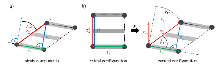
Fig. 1. (a) Transverse strain 𝜀2 versus perpendicular strain 𝜀⊥; (b) deformation of line segments 𝒕1, 𝒕2 and 𝒕⊥ , based on [11], [15]
In the corresponding alternative intermediate configuration, the nominal stress tensor 𝑷̲∗ can be formulated based on an orthogonal material stiffness matrix by:

accounting for large shear strains 𝛾12 and the non-orthogonal linear strains 𝜀1, 𝜀2. In this intermediate configuration, the line segments remain in their initial orientation, elongated to the current configuration, based on an alternative decomposition of the deformation gradient 𝑭 described in [11].
To account for elastic-plastic behaviour, the total tensile strain 𝜀2 and the total shear angle 𝛾12 are composed of elastic as well as hardening plastic parts [11]. A yield condition defines the transition from elastic to plastic domain. Material parameter fitting led to the conclusion, that in case of tensile loading of the stitching, the respective yield surface 𝑅2Γ(𝜀2,𝑝,𝛾12) depends on the plastic strain 𝜀2,𝑝 as well as on the shear angle 𝛾12, while in case of shear loading the yield curve 𝑅12Γ(𝛾12,𝑝) only depends on the plastic shear 𝛾12,𝑝.
Transverse compression can only be transmitted perpendicular to the carbon fibres. This compressive stress 𝑃⊥ is modelled via a superimposed nonlinear elastic material law depending on 𝜀⊥ and 𝛾12 to account for the fact that macroscopic wrinkling starts at higher in-plane transverse compression in case of high shear angles [11]. If perpendicular strain 𝜀⊥ and transverse strain 𝜀2 have equal sign, disjunction needs to be ensured. Therefore, the transverse stress 𝑃22∗ is set to zero for 𝜀2<0 and the perpendicular stress 𝑃⊥ is set to zero for 𝜀⊥>0. A more detailed description of the non-orthogonal-plastic UD-NCF membrane model is given in [11]. The model parameters for shear and transverse tension have been identified based on experimental off-axis tension (OAT) tests of UD-NCF with three different fibre orientations 𝜃={30°,45°,60°} [11], [17].
The bending behaviour of UD-NCF is modelled by a hypoelastic approach, initially introduced for thermoplastic UD-tapes [18]. Bending stiffness stays orthogonal in case of large shear deformation and only requires an accurate rotation of the unidirectional carbon fibres (line segment 𝒕1). The behaviour is assumed to be linear elastic and is defined by the bending stiffness in fibre direction 𝐸||B and negligible stiffness perpendicular 𝐸⊥B to the fibres.
2.2 Forming simulation model
The forming simulation model is implemented in ABAQUS. Since the high membrane stiffness in fibre direction is combined with a very low bending stiffness, the deformation behaviour cannot be captured by conventional shell theories based on Cauchy mechanics. Therefore, membrane and bending behaviour is modelled by superimposed finite membrane and plate elements. The non-orthogonal elastic-plastic material model of the membrane behaviour is implemented in a VUMAT subroutine [11]. For the plate element, a user-defined shell section integration is implemented in a VUGENS subroutine [18]. The interface behaviour between the individual plies as well as between tool and plies is modelled by combined normal and tangential contact, depending on normal pressure, slip-rate and adhesion [18]. The contact model is implemented in a VUINTERACTION subroutine.
2.3 Prediction of forming effects
Forming of UD-NCF is largely determined by the low shear and low transverse stiffness that highly depend on the type of stitching and on the slippage between stitching and fibre yarns. The fibre orientation of the current configuration 𝒕1= 𝑭∙𝒕10 is computed by the initial fibre orientations 𝒕10 and the deformation gradient 𝑭. The shear angle 𝛾12 results from Eq. (2). Transverse tensile or compressive deformation leads to gapping between fibre yarns or transverse compaction, respectively. Furthermore, mesoscopic buckling of the fibre yarns may occur due to lateral contraction of the stitching [16]. Assuming a constant fabric weight, the fibre volume content (FVC)

depends on the initial FVC 𝜑𝑓0 and on the ratio between the initial area 𝐴0 and the deformed area

In addition to fibre orientation, shear angle and FVC, the modelling approach provides indication to analyse three further forming effects: gapping, transverse compaction and fibre waviness [15], [17]. Thereby, observations based on extensive OAT tests have shown, that the non-orthogonal tensile strain component 𝜀2 (stitching) is not suitable for indicating gapping nor transverse in-plane compressive behaviour. Component forming simulations have shown that the perpendicular strain component 𝜀⊥ is more suitable for that purpose, to indicate, where gapping corresponds to tensile strains and compaction to compressive strains [11].
Fibre waviness occurs at meso scale and cannot be captured macroscopically. Such undulations typically arise in regions with compressive fibre strain, 𝜀1<0, due to fibre buckling. Hence, an assessment of the amplitude to wavelength ratio 𝐴λ/𝜆 can be deduced from 𝜀1. However, it depends on the compressive stiffness of the fibre yarn, which has not been measured and thus impedes a quantitative evaluation. Nevertheless, a qualitative evaluation of the susceptibility to waviness can be conducted, e.g., for varying process conditions [15].
3 Application, results and discussion
3.1 Reference structure and experimental test setup
An L-shaped geometry as shown in Fig. 2a is chosen to analyse the different types of forming effects qualitatively and quantitatively. Due to the multiple curvatures and draft angles, locally varying degrees of forming can be observed. Furthermore, nineteen individually controllable blank holders are installed (Fig. 2b) to manipulate the draping process and to influence the formation of draping effects like waviness, gapping or compaction [4],[15]. In the experimental test programme, two-layer and eight-layer unidirectional (UD) and bidirectional (BD) layups of carbon fibre (CF) UD-NCF (Zoltek PX 35 50 K, 338 g/m²) were formed using different blank-holder configurations.

Fig. 2. (a) L-shaped geometry. (b) Forming tool with 19 controllable blank holders and L-shaped negative mould. (c) Top and bottom view of a UD-NCF preform with 8 layers Zoltek PX35 and with a red dot grid printed on top layer [4]
To analyse the resulting fibre orientations and the extent of forming effects in inner layers, a contrast-enhancing ink used in X-rays is printed in a dot pattern on the fibre bundles (Fig. 3a) and is evaluated by radiography images [4]. To analyse outer plies, the method can also be applied with simple coloured points and a photo camera, cf. Fig 2c (top). In this way, the deformation of individual fabric plies can be quantified locally, which gives a direct measure for the fibre orientation as well as for forming effects like gapping and transverse compression, and thus enables an estimation of the local fibre volume content [17]. Based on the measurements, a comparison with forming simulation can be conducted by exporting the coordinates of the acquired 3D points and computing the deformation gradient in relation to the reference state. Thus, a high-resolution quantification of the forming effects becomes feasible for inner plies, cf. Fig. 3.
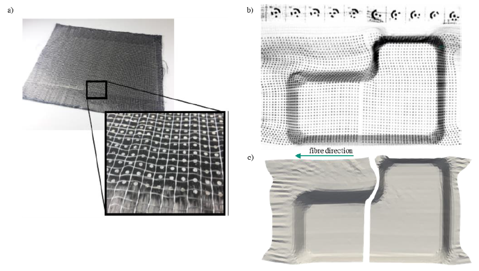
Fig. 3. (a) Silver dot grid on semi-finished NCF. (b) Detected dot grid on a deformed UD-NCF with associated reference markers [4]. (c) Deformed UD-NCF layer, deduced from the radiographic measurements
3.2 Comparison of experimental and simulation results
For experimental analysis, the dot grid is applied on the fourth layer (Fig. 3a) and three preforms of identical configuration are evaluated to account for the scattering during forming. A comparison between the three configurations showed a very good agreement with negligible deviations. After forming, the coordinates of the displaced dots and the resulting local deformation gradients are determined. Based on the deformation gradient, local fibre orientations, area changes and strain measures can be evaluated. According to the UD-NCF material model presented in Section 2.1, relevant strain measures are the strain components 𝜀1 of the fibres and 𝜀2 of the stitching, the perpendicular transverse strain 𝜀⊥ and the shear angle 𝛾12 between the fibre direction and the second material axis. These can be evaluated and compared to simulation results.
For forming simulation, the FE model is built up with superimposed membrane and shell elements as described in Section 2.2. The geometry and the blank holder configurations are defined according to the experimental test setup. To compare experimental and numerical results, they are transferred to a neutral VTK format and to a uniform mesh. The mapping library MpCCI.MapLib from Fraunhofer SCAI [19] is used to map both, the data from the experiments and the data from the simulations, to the uniform mesh.
The comparison between experimental and simulation results is illustrated in Fig. 4 and shows good agreement regarding fibre orientation 𝛼 and local area change det(𝑭), with an average deviation of only ±2° in fibre orientation and ±3% in fibre volume content. Since the thickness of the stack is defined by a constant cavity height, the area change is directly related to the fibre volume content. The largest deviations occur in areas, where the preform recedes after removal from the mould. Similarly, a good agreement of the shear deformation 𝛾12 could be observed, with only about 2° mean shear angle deviation.
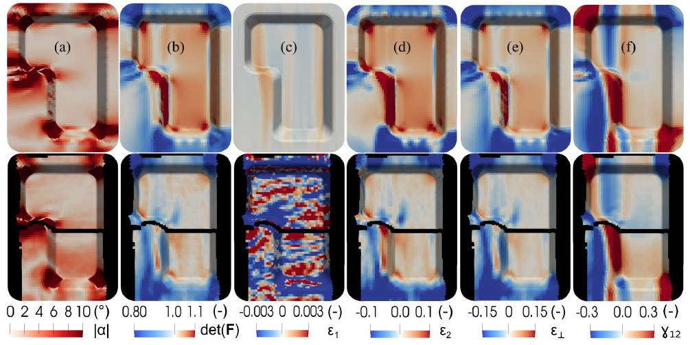
Fig. 4. Comparison between draping simulation (top) and experiment (bottom, black areas without measurement result): (a) deviation from initial fibre orientation, (b) local area ratio, (c) roving elongation, (d) sewing thread elongation, (e) transverse elongation to fibre direction, and (f) shear
The largest deviations occur in the elongation 𝜀1 in fibre direction and 𝜀⊥ in perpendicular direction, as well as in the elongation 𝜀2 of the stitching. Due to the assumption of very stiff fibres, the predicted fibre strain in the simulation is very small, whereas the experimental tests show diffuse and wave-like strains, which oscillate between compression and elongation, though at low strain level. In the centre of the geometry a high degree of compression is noticeable and, in this region, a locally clearly visible waviness was found, which indicates the assumption of negative strains in fibre direction as an indicator for the onset of waviness. Similar irregular distributed 𝜀1 strains have been observed in OAT tests in case of mesoscopic carbon fibre tow buckling due to lateral contraction of the stitching [11]. The largest deviations in the elongation 𝜀2 of the stitching arise in the area of the inner long side of the L-shaped geometry and in the bottom area, where different running lengths are realized. One possible reason is that the approach presented in Section 2 does not restrict slip between carbon fibre, stitching and glass fibre, and thus, neglects potential load transmission via the glass fibre. This leads to satisfactory results in case of moderate deformations and low blank holder forces [15], but may lead to noticeable deviations, if slip is restricted. For a more accurate prediction of 𝜀1 the material behaviour in fibre direction needs to be modelled more accurately and advanced modelling approaches are required to capture in-plane fibre bending. Currently, the compressive stiffness in fibre direction is set equal to the constant tensile stiffness and buckling is neglected. Negative 𝜀1 would then indicate an occurrence of waviness, which in turn leading to non-linear behaviour of the modulus in fibre direction and to in-plane bending of the roving. In-plane bending cannot be captured by approaches based on Cauchy mechanics and requires generalized continuum approaches [20]. Introducing an in-plane fibre bending stiffness, would also enable shear stiffness parallel to the fibre tows (21-shear) to be modelled differently from the macroscopic shear stiffness perpendicular to the fibre tows (12-shear). Experimental tests show that shear deformation primary occurs parallel to the carbon fibres, since in-plane bending stiffness of the carbon fibre tows hinders shear deformation perpendicular to the carbon fibres.
4 Conclusions
A macroscopic modelling approach for unidirectional non-crimp fabrics (UD-NCF) is evaluated for its accuracy in predicting global and local forming effects. The prediction accuracy is validated by experimental tests, where full-field strains are measured by projectional radiography. The modelling approach allows for the prediction of fibre orientations, shear angles and fibre area changes, which all show good agreement with experimental results. Based on its strain measures, the model can also provide indication for fibre waviness, gapping, and transverse compaction. Fibre waviness can be deduced from negative strains in fibre direction, provoking fibre buckling. For a quantitative evaluation, however, the compressive stiffness in fibre direction needs to be known. Furthermore, advanced generalized continuum approaches are required to capture in-plane fibre bending and the resulting reduced stiffness in fibre direction. Consequently, the proposed macroscopic approach can provide only a qualitative, but no quantitative estimation of forming-induced fibre waviness. Transverse compaction and fibre gapping can be deduced from the strain measures transverse and perpendicular to the fibres. Both show some deviations from experimental results particularly in areas, where varying running length in fibre direction need to be formed. To predict gapping and transverse compaction accurately, the multiscale nature of UD-NCF needs to be captured entirely. This includes slip modelling between carbon fibre, stitching and glass fibre, which depends on the deformation state and on boundary conditions. While meso-modelling can capture this behaviour intrinsically, a homogenised formulation for macroscopic modelling remains challenging.
Acknowledgements
The research documented in this manuscript has been funded by the German Research Foundation (DFG), mainly within the project “Experimental and virtual analysis of draping effects and their impact on the structural mechanical behaviour of fibre composite components” (No. 287275762) and subsequently within the DFG-ANR project “Composite forming simulation for non-crimped fabrics based on generalized continuum approaches” (No. 431354059). The support by the DFG is gratefully acknowledged. The work is also part of the Young Investigator Group (YIG) Tailored Composite Materials for Lightweight Vehicles, thankfully funded by the Vector Stiftung. The authors are also grateful to Fraunhofer SCAI for freely providing MpCCI MapLib.
