1 Introduction
Thermoplastic pressure tanks and vessels are manufactured with online consolidation processes such as tape placement and filament winding. These processes are usually associated with high thermal and crystallinity gradients through the parts’ thickness, causing residual stresses that arise during cooling from the processing temperature to the ambient one. The formation of residual stresses is mainly due to mismatch in thermo-mechanical properties, microscopically between the fibers and the thermoplastic resin and macroscopically between tapes at different orientations. Other factors can cause the formation of residual stresses such as winding tension, geometric constraint imposed by the mandrel [1,2] and moisture gradients. Their presence may cause dimensional instabilities, micro cracks, delamination and reduction of the load resistance capability [3]. Hence, their estimation appears as a compulsory stage in the parts design process in order to assess the parts’ reliability under real service and understand the effect of the process conditions on these stresses.
The two main techniques used to predict the residual stresses are mainly the Finite Element Method (FEM) and the classical laminate theory (CLT). The CLT is less computationally expensive than FEM but needed to be modified to correctly predict the behavior of thin unsymmetrical cross-ply laminates [4]. The correction was based on the introduction of non-linear strain-displacement relationships and the final version of the theory is called the modified CLT. Previous works on residual stresses were carried in the case of press molding [5, 6, 7]. Cirino and Pipes [8] established a model for hoop-wound rings with constant properties and uniform cooling. A transient model was proposed in [1] during filament winding but led to excessive computational time. Moreover, a FEM based model was established in [9] for the tape-placement but it was verified using experimental data from press molding. Experimentally, destructive and non-destructive techniques can be used to measure the residual stresses on the ply level. Destructive techniques include first ply failure [6, 10], blind hole drilling [11], compliance method [12] and layer removal method [5]. Non-destructive techniques have been widely studied and used to measure the residual stresses. From these techniques, one may cite interferometry [13] and Raman spectroscopy [14].
In this work, the model based on the modified CLT developed in [15] for the study of the residual stresses during compression molding has been adapted to study the formation of theses stresses during tape placement on the SPIDE-TP, an online consolidation process based in Cetim, Nantes-France. The mechanical model is enriched with a complex representative thermal history and fed with crystallization and thermomechanical properties of the material described in the next sections. In addition, an experimental campaign was conducted, firstly to understand the material behavior through its characterization and secondly to validate the numerical model by measuring the variation of the curvature of laminates with temperature. To this end, laminates were manufactured with different thicknesses and using two different mandrel temperatures. This finally led to an estimation of the residual stresses present in the laminates, and to a better understanding of the effect of mandrel temperature and annealing on the stresses.
2 Materials and characterization methods
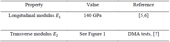
Unidirectional pre-impregnated tapes from Solvay made with PolyEtherEtherKetone (PEEK) 150G reinforced with AS4 carbon fibers at a volumetric ratio v𝑓=0.59 were used to elaborate unidirectional (UD) and unsymmetrical (903/03) cross-ply laminates using different stacking sequences and two different mandrel temperatures: ambient 25°C and 180°C. The mechanical properties required to feed the thermomechanical model are listed in Table 1. Experimental values are used when experimental characterization took place, otherwise values from literature are considered. When the values from literature are considered, the composite properties of interest are therefore estimated from those of the fiber and the matrix using homogenization techniques [16].
Table 1 – Longitudinal and transverse modulus
Dynamic Mechanical Analysis (DMA) tests in the three-point bending mode were conducted on the unidirectional laminates to measure the transverse elastic modulus 𝐸22.
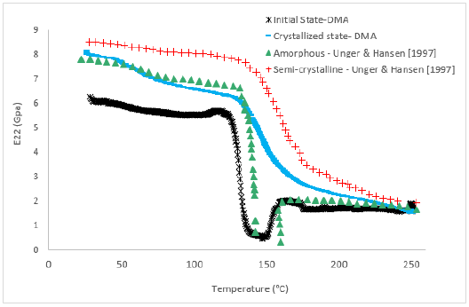 Figure 1 - Transverse modulus for the material obtained with DMA and compared with results from [7]
The evolution of 𝐸22 for the PEEK/AS4 from unidirectional laminates with the mandrel at ambient temperature are presented in Figure 1. The initial state corresponds to the material tested after processing. The values were compared to results from [7] where measurements were conducted on a similar material. For this initial state of the material, the behavior in the transverse direction shows a trend similar to that of a quenched specimen in the study mentioned, therefore a material with very low crystallinity. The modulus exerts a sudden drop around the glass transition 𝑇𝑔=135°C followed by an increase around 160°C. This increase in stiffness is due to the cold crystallization. After being subjected to an annealing, the transverse modulus of the annealed material is therefore presented in the blue curve and can be compared to the behavior of a semi-crystalline material. The transverse behavior for the specimens fabricated using the hot mandrel is similar to that of the semi-crystalline specimens.
The thermal expansion coefficients 𝛼𝐿 and 𝛼𝑇 along the longitudinal and transverse direction respectively were also estimated from those of the carbon fiber and PEEK. AS4 carbon fibers are transversely isotropic, their coefficients of thermal expansion in the longitudinal and transverse directions are respectively -0.9 10-6 K-1 and 7.2 10-6 K-1[17]. PEEK has been tested using PvT-XT volumetric dilatometer in [18], this type of device measures the evolution of the specific volume of the material with temperature. Based on this evolution, the linear thermal expansion coefficient of the PEEK and its crystallization shrinkage can be obtained using the method in [16].
3 Curvature measurement
The method used in this work to access the residual stresses relies on the measurement of the laminates curvature variation with temperature. Upon cooling from the melt, the plies contract primary in the direction transverse to the fiber axis. In symmetrical cross-ply laminates, the contraction of each ply is constrained by the adjacent ones resulting in residual stresses building-up. For an unsymmetrical cross-ply laminate, the residual stresses are partially relieved by out-of-plane deformation, and the plate tends to curve. Therefore, a simple mean to assess the residual stresses is by measuring the curvature that occurs in unbalanced cross-ply laminates. Strips specimens of 15*150 mm2 were selected from the unsymmetrical laminates listed in Table 1. These specimens were placed in a climate chamber and were subjected to consecutive heating and cooling up to different temperatures: 120 and 150°C. The variation of their curvature with temperature was monitored by taking photos of the specimens at different temperature steps. These photos were later post processed to obtain the curvatures of the specimens. In fact, at each temperature step and for each specimen, coordinates of points were selected to obtain the radius of the circle passing through these points. The problem is therefore finding the solution for the following system of equation for each specimen.

𝑥1,𝑥2, 𝑥3, 𝑦1, 𝑦2 and 𝑦3 are the coordinates of the points chosen on the strip specimen, 𝑥c, 𝑦c those for the center of the circle passing through these points and 𝑟c is the radius of this circle. The curvature к (𝑚−1) is:

4 Numerical methods
A. Thermal Model
Since the specimens studied are placed in a climate chamber after the process, the thermal history to which they are subjected can be divided in two parts. The first part is a complex thermal load during the process including fast local heating with the laser source up to the processing temperature followed by fast cooling in the case of cold mandrel. The second part describes what happens in the climate chamber, and this includes a simple heating and cooling since the specimens were maintained long enough on each temperature step to ensure a homogenized temperature through the thickness before measuring their curvature. For the first part, the thermal history is based on a previous work [19] on the same process and the details for this model can be found in the mentioned reference. Density, specific heat and thermal conductivity are essential to solve the thermal model. Thermal conductivity follows the same anisotropy as the carbon fiber [20]. Thermal capacity and density on the other hand were obtained using the law of mixture. AS4 carbon fibers’ properties are constant with temperature and are found in [20], while the PEEK’s density and specific heat are temperature-dependent and can be found in [21] and [20] respectively.
In the case of a six plies laminate, the evolution of the plies’ mean temperature with time during the process is in Figure 3. The time between two consecutive peaks corresponds to the time of deposition of one ply. It can be seen that all the plies are subjected to the same thermal history. Upon deposition, they’re heated with the laser source up to the processing temperature above the fusion temperature of the PEEK 𝑇𝑓=340°C. Once the laser has passed, the ply in consideration undergoes a fast cooling followed by a reheating when the next ply is placed. However, the model shows that upon reheating, the temperature of the plies doesn’t exceed the glass transition temperature.
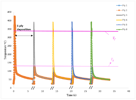 Figure 2 - Evolution of the mean temperature of different plies of a laminate during the process
B. Crystallization Model
Most of the crystallization models described in the literature are based on the theoretical work by Avrami [22], Nakamura [18]and Tobin [23, 24]. These theoretical works were originally intended for isothermal crystallization, however modifications were brought to make them suitable for the description of the non-isothermal crystallization. The model used is the one used in [23] which was proposed by [24]. It correlates well with the experimental measurements for the non-isothermal crystallization as described in [24]. The evolution of the crystallinity relies on the thermal load. Figure 3 (b) shows the evolution of the crystallinity with time during the process for the forth ply when producing a six plies laminates. During the process, the ply is subjected to high cooling rates which leads to the low crystallinity level. Since the ply’s temperature doesn’t exceed the glass transition of the matrix when reheated during the deposition of the consecutive plies (fifth and sixth), no enhancement of crystallization occurs. This low level of crystallinity was also observed in [23] during tape placement and explains the behavior of the material observed during DMA tests where the material’s behavior is similar to that of an amorphous one described in [7].
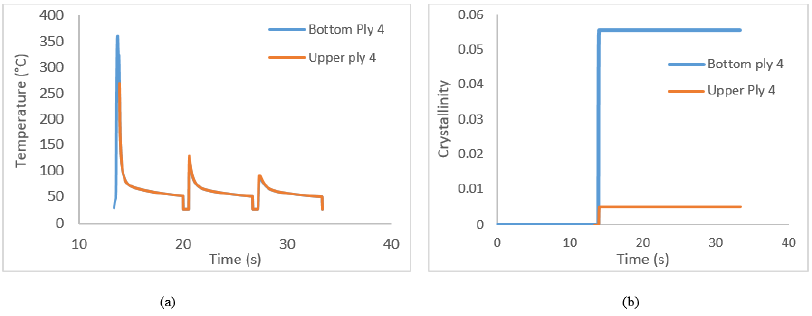 Figure 3 - (a) Evolution of the temperature in the upper and lower parts of the fourth ply during the process, (b) Evolution of the crystallinity in the corresponding ply using the model developed in [23]
C. Thermomechanical model
The model used in this work was developed in [25] during compression molding and is applied here for tape placement. Details for this model can be found in [25].
5 Results and discussions
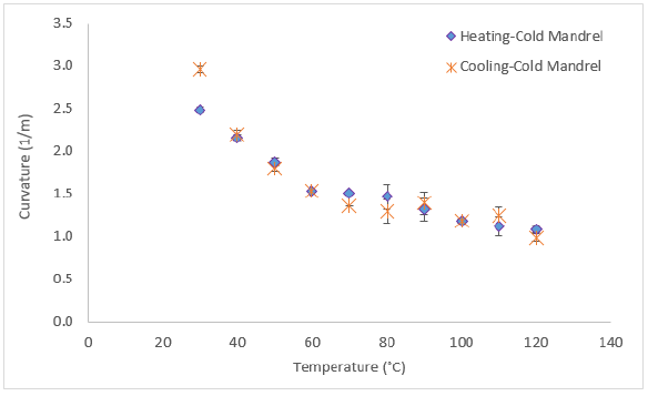 Figure 3 - Evolution of the measured curvature with temperature for [903/03] manufactured with cold mandrel
Figure 4 shows the evolution of curvature with temperature for (903/03) laminates manufactured with the cold mandrel when heated up to 120°C and then cooled down. The curvature’s evolutions with temperature during heating and cooling are similar. In fact, the maximum temperature doesn’t exceed the glass transition temperature, therefore no modification on the behavior of the material is induced during heating. The maximum deviation for the (903/03) is 3.2% which shows a good reproducibility of the experiment over the different tested samples.
The evolution of curvature with temperature for (903/03) laminates fabricated with cold mandrel and hot mandrel are presented in Figure 5 (a) and (b) respectively when heated and cooled from 150°C. In fact, above 𝑇𝑔 and as previously shown with the DMA test, a cold crystallization occurs for the specimens fabricated with cold mandrel, this is usually associated with a shrinkage leading to an increase in the curvature. This increase is shown during isothermal heating at 150°C and is approximated around 17% in the case of laminates fabricated with cold mandrel. This increase is negligible in the case of cold mandrel and can be attributed to errors in measurement or stress relaxation.
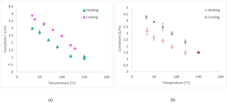
Figure 4 - Evolution of the measured curvature with temperature for [903/03] manufactured with (a) cold mandrel and (b) hot mandrel
The results from the thermomechanical model are compared with the measured ones in the case of the (903/03) strip specimens fabricated using the cold mandrel during cooling from 120°C and 150°C in Figure 6 (a) and (b) respectively. During the process, the material is attached to the mandrel, no curvature is therefore observed. After demolding, the strip specimens present a curvature due to the presence of the residual stresses.
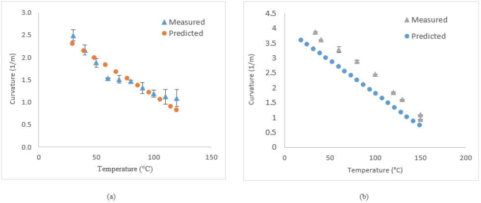 Figure 5 - Comparison between measured and simulated curvature during cooling from (a) 120°C and (b) 150°C
For the first case in Figure 6 (a) when the maximum annealing temperature is 120°C, numerical results are identical to the measured ones. The small deviation between them can be attributed to defects in the specimens which were not considered in the model. In addition, difficulties in controlling the temperatures of the climate chamber close to the ambient one can also originate these deviations. Figure 6 (b) compares the numerical results with the experimentally measured ones when the maximum annealing temperature is 150°C. While the results are close, there’s a slight underestimation by the model. In fact, the material behavior is considered to be completely elastic, however it was reported that PEEK has a viscoelastic behavior [5], and stresses tend to relax which therefore implies a further increase in the curvature. So the difference between results can be attributed to this cause.
From the curvature, the model is capable of providing the stresses state in the studied laminate.
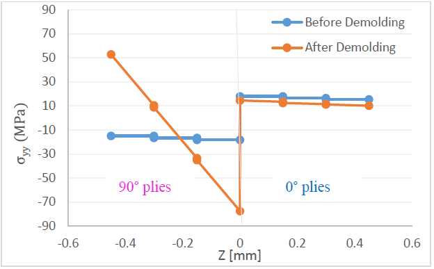 Figure 6 - Distribution of residual stresses through the thickness in the global coordinates
Figure 7 presents the stresses distribution in the laminates before and after demolding. Before demolding, along the y-direction which is the transverse direction for the 0° plies and the longitudinal direction for the 90° ones, the 0° plies tend to shrink, however their shrinkage is restrained by the 90° plies which leads to tensile stresses in the 0° plies and compressive stresses in the 90° plies along this direction The maximum tensile stress is located at the center of the laminate and is equal to 20 MPa, the maximum compressive stress is located also in the center of the laminate and is equal to -20 MPa. The opposite phenomenon is observed along the x-direction. After demolding, the residual stresses already accumulated generate a curvature, therefore part of the stresses are relaxed and a new distribution of stresses is observed through the thickness.
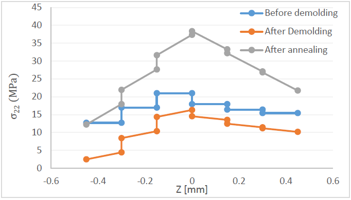 Figure 7 - Distribution of transverse residual stresses through the thickness in the local coordinates
In the local coordinates, before demolding : plies at high temperature tend to shrink during cooling along their transverse direction but this shrinkage is restrained by the surrounding plies, therefore they’re all subjected to tensile stresses along their transverse direction. And the maximum stress is located at the center of the laminate with a maximum value reaching 20 MPa. After demolding, the curvature generation modifies slightly the stresses distribution along the thickness of the laminate. After annealing at 150°C, an increase in the crystallinity takes place due to cold crystallization therefore leading to an increase in the modulus of the material. This leads to an increased residual stress with a maximum vale that can reach up to approximately 40 MPa at the center of the laminate as shown in Figure 8.
6 Conclusions and discussion
Curvature variation with temperature was measured for cross-ply laminates fabricated using the SPIDE-TP. These measurement alongside DMA tests showed that the material present a low crystallinity after the process in the case of cold mandrel. The thermomechanical model developed in [25] was used to predict the curvatures and residual stresses. The model was capable to correctly predict the curvatures when the specimens were heated below the glass transition temperature and a slight deviation from the experiment was observed in the case of temperature above the glass transition. This deviation can be attributed to the viscoelastic effect of the material allowing some stresses to be relaxed and thus increase the curvature of the specimens. Transverse residual stresses were evaluated from these curvatures and a maximum tensile stress was estimated in the center of the specimens and reached values of 20 MPa after processing and 40 MPa after annealing. These values should be considered since the ultimate tensile strength of PEEK is evaluated at around 90 MPa, when placed with carbon fibers at a volumetric fraction around 60%, this maximum stress becomes around 50 MPa, and therefore values of 40 MPa can initiate delamination and cracks initiation. Based on the given, it is crucial to determine the residual stresses prior in the fabricated parts prior to their placement in service to prevent failure of the structure.
