1 Introduction
Tube hydroforming is a well-known technology for the production of lightweight, high strength and complex shape hollow components. A straight tube is first bent, if the final shape demands such an operation, then is preformed with the closing of a twosided tool and finally inflated or expanded by the use of pressurized media. The main advantages of the resulting component are the low weight and the high stiffness, which enables reducing the initial tube thickness to produce high strength lightweight components [SCH98, SIE98, VOL99, AHM00].
During the tube hydroforming operation the tube is sealed by two axial cylinders. Lateral forces of these cylinders avoid the leakage of pressurized water-oil emulsion and additionally feed material from the guiding or feed zones to the expansion zones. One can understand this working principle as it is similar to the deep drawing, where material is fed from the blank-holder zone to the die cavity. At this stage, the reader may have already noticed that friction is very critical in tube hydroforming. A high friction makes the feeding of material to critical areas impossible and premature cracks appear during the process. As the contact pressure is high (normally in the range of 100-120 MPa) and the contact surface is large, the friction forces represent a big portion of the needed axial forces. The rest of the needed axial force is proportional to the internal pressure used in the process, which needs to be counteracted by the external push rods. Consequently, the correct estimation of friction forces is important for a good sizing of axial cylinders and an unfailing tool and process design.
According to Fig. 1. three different zones can be defined in hydroforming, the so-called guiding or feed zones, the transition zones and the expansion zones. The later typically defines the component geometry and is machined to the nominal geometry of the component. As explained before, the guiding zones act as a reservoir of material. At this zone, the tube suffers axial compression together with through thickness compression caused by the internal hydrostatic pressure. The tool diameter in these areas is slightly larger than the nominal tube external diameter to ensure that despite the tube manufacturing fluctuations, the initial workpiece can be inserted in the tool cavity and closing of the tool does not plastify or pinch the tube. This initial gap, of about 0.25-0.5 mm in diameter, is eliminated when the tube is pressurized and reaches the critical expansion pressure.
For this reason, homogenous contact is only available at this area when the tube is slightly expanded in the circumferential direction and only after yielding of the tube occurs. After this expansion, the apparent contact pressure between the tube and the tool is nearly equal to the internal pressure of the pressurized media.
The transition zone is defined by smooth sweep like geometries and serve as a transition between the guiding zones and the desired component geometry. The radii of these areas suffer the highest contact pressures of the tool, as it happens in the entrance radii and punch radii of a stamping tool. The pressure that acts in the free areas of the tube are supported by these areas of the tool and thus the contact pressure is high at this transition features. The tube is typically axially compressed and circumferentially expanded in these zones. The compression level depends on the capacity of feeding material from the guiding zones to these transition zones, which is directly linked to friction.
Finally, the expansion zone defines the component geometry. Normally plane strain or biaxial strain conditions are present in these areas of the tube. The contact only occurs at the final stages of the process and when the tube is almost completely inflated. At this stage through thickness compression stresses arise and friction becomes a critical aspect that governs the local thinning of these areas and the filling of small details that are present in the tool. Considerable surface expansions are typically observed in these areas, which considerably changes the tube outer surface micro-topography. For this reason, the tribological conditions in the expansion zones are different from the ones observed in the guiding zones. Surface expansion normally reduces the friction coefficient in comparison to non-deformed outer surfaces.
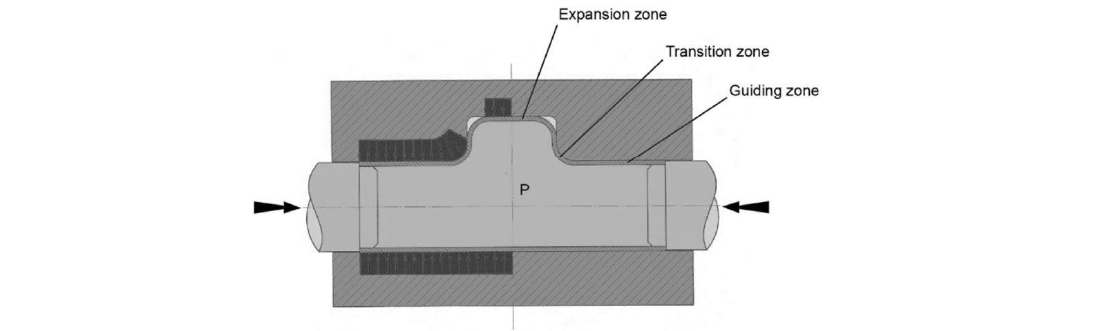
Fig. 1. Different tool zones in tube hydroforming
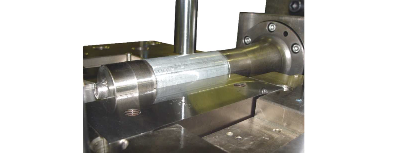
Fig. 2. Tube sliding test facility of Mondragon University
Finite element assisted process design is well stablished in the automotive and aeronautical sectors for hydroformed components and is an effective step for a fast and reliable tool design. Traditionally, the coefficient of friction has been considered to remain constant during the simulation of a hydroforming process of a component. However, some stamping studies discussed the possibility of applying different constant coefficient of friction for each surface that is in contact with the sheet [SAN08]. More recent tribological studies have revealed that the coefficient of friction is affected by several contact features. In this way some authors have developed variable coefficient of friction models based on micro-scale contact behaviour [HOL12, KAR14] or macro-scale [FIL11, TAM16, TRZ19] ones. In both cases there is a generalized agreement that coefficient of friction is affected by the contact pressure and the sliding velocity [MER14]. As the contact pressure is increased, the irregular topography of the contact surfaces are subjected to a flattening of each asperities, so the contact geometry changes resulting in a change of the coefficient of friction [MA10]. On the other hand, increasing the sliding velocity also decreases the friction of coefficient. According to the principle of tribology, under the boundary lubrication condition, the friction coefficient is mainly composed of fluid friction coefficient and solid friction coefficient. With increasing sliding velocity, the area of solid friction decreases gradually and leads to a decrease in the coefficient of solid friction. The local heating effect of the friction at the peak causes the viscosity of the lubricant to decrease and leads the coefficient of fluid friction to decrease. As a result, the friction coefficient decreases with increasing sliding speed [DOU19].
The use of contact pressure and sliding velocity dependant friction laws is being progressively introduced in industrial stamping companies with the use of Triboform software launched by Autoform. Recent industrial studies have proven that accuracy of numerical results increases when these new models are used [GIL16, SIG16, HOL17, SIG19]. Recently, first studies have been published where temperature dependant friction laws have been used in order to capture the heating up of the tools until the steady state production run is stablished [GRÜ09, WAA20]. Anyhow, none of these friction laws have been employed in tube hydroforming process modelling and their effect is unknown for the tribological conditions that are present in hydroforming (high contact pressures, variable sliding velocities and large surface expansion).
2 Friction characterization in hydroforming. Objectives
Three kind of tests have been used in hydroforming for friction coefficient measurements. The most common test used by several authors is the pressurized tube-sliding test, also called push through test. The test was first presented by researchers from the Institute for Production Engineering (PtU) in Darmstadt to emulate the tribological conditions of the feeding zone [PRI99, PRI01a]. During the test, a straight tube is pressurized until homogeneous contact between the tool and the outer surface of the tube occurs and is subsequently pushed by the use of one or two axial cylinders. The resulting friction force can be measured directly from the axial cylinders or indirectly from the reaction force that appears in the tool by the use of force transducers. The test can be performed using either a vertical or a horizontal configuration. In the vertical configuration, the tool is normally manufactured in a single part and the contact pressure is estimated from the internal pressure, making the hypothesis that the contact pressure is equal to the tube internal pressure. In the horizontal option, the die is split parallel to the tube horizontal axis and the contact pressure is calculated by measuring the vertical reaction of one of the half dies by using load sensors. In both cases, any friction between the dies and the moving punches is to be avoided and the dies must ideally lay on axial bearings to avoid any loss of transmitted forces. The Ohio State University and Paderborn University used the same principle to study the behavior of different lubricants [AHM00, VOL02, PLA03] as it is a straight forward method to calculate the friction coefficient. Other similar more recent studies are [HWA05, YI11].
The second popular test is the tube-upsetting test and was initially created to estimate the friction coefficient in the forming or expansion zone of the tooling, although no biaxial surface expansion occurs during the experiment [VOL02, PLA03, PLA05]. During the test, a straight tube is continuously upset in a closed die while pressurized by an internal pressure. Due to friction forces the wall thickness increases non-uniformly being thicker in the moving punch side. The thickness distribution is used to estimate the friction coefficient by inverse numerical simulation and is therefore an indirect measurement system [FIO13, RUD17]. The test does not reflect the tribological conditions that are present in the forming zone and is more suitable for the feeding zone evaluation.
Thirdly, specific tests for the estimation of the friction coefficient in the expansion zone were developed. The same group that developed the tube-sliding test used a modified version of the method to evaluate the friction between the die and the tool after considerably expanding the tube using spacers [GRO02, GRO03]. Additionally, and in the same study, a special tool was constructed where 4 component load cells were used to monitor the forces in the transition radii and estimate the friction coefficients in these zones. A similar approach was used years before by Dohman et al. with the same aim [DOH97]. These last methods were complicated to be reproduced and several researchers used a more simple methodology, the corner-filling test, to estimate the average friction coefficient in the forming zone. In [NGA04] a pear-shaped tube expansion test was used to calculate the friction coefficient by inverse analysis. Similar approach was used in [YI11] to calculate the friction coefficient by using three different expansion shapes, including a square section die. A recent work used a square section tool equipped with three sensors [ABD17] in order to calculate the average friction coefficient out of the tube expansion versus time curves measured in the corner areas. In [KOÇ03], an industrial frame hydroforming process was used to estimate the coefficient friction using inverse simulation techniques.
All in all, and unlike in stamping, very few studies have been found where pressure and sliding velocity dependant friction laws have been used to numerically model the hydroforming processes by finite element modelling. Only Groche et al. used an adaptive friction model to estimate the process feasibility of a T-Shape component [GRO05]. The developed friction law was normal pressure, sliding velocity and surface expansion ratio dependant. Wall thickness distribution and dome height were measured experimentally and compared with the numerical results obtained with the adaptive friction law and with a conventional constant friction coefficient of 0.04. The later value was the result of a numerical optimization of friction coefficient with respect to wall thickness and dome height of the real experimental component. The study showed that an adaptive friction model provides more accurate results than a constant friction model. In the specific case study, only one relevant thickening area was predicted by the constant friction model while the adaptive model predicted two heavily thickened areas, like in the real component.
For the above mentioned reasons, the final objective of this ongoing work is to analyse the influence the variable friction laws have on the final numerical results of hydroforming. For this purpose, three different lubricants have been tested using the pressurized tube-sliding test. The viscosities of lubricants have been selected to cover a wide range of hydroforming applications. Low viscosity lubricants are used in the automotive sector to facilitate the final cleaning of the components while high viscosity ones are used in the aeronautical sector to enable the forming of very complex components. Some researchers proved that friction coefficient is very dependent on the lubricant viscosity and performed experimental tests using different sliding velocities and punch radii [LEE02, KEU04] using flat sheets and relatively low apparent contact pressures. Similar analysis has been performed in this paper for hydroforming applications using two low viscosity and a very high viscosity mineral oils.
Tube sliding tests have been performed using different internal pressures and tube pushing velocities. These experimental results have allowed fitting variable friction models which are contact pressure and sliding velocity dependant. Surface micrographs have been obtained from tested tubes trying to identify the mechanisms that occurred during the test in the most damaged contact areas and for different lubricant viscosities. In the near future, the validity of the newly developed friction models will be evaluated by the hydroforming of a triangular shape component and the comparison of numerical and experimental results.
3 Tube sliding tests
3.1 Tube material and lubricants
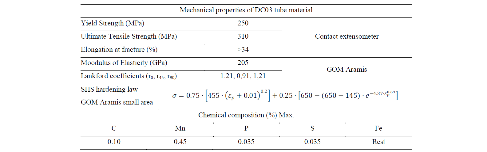
Roll formed and high frequency welded tubes have been used in the study. The raw material of the tubes is a DC03 cold rolled and annealed mild steel of 1.35 mm of thickness. The mechanical properties of the tube material obtained from uniaxial tensile tests of samples cut from unfolded tube precuts are shown in table 1. The outer diameter of the tube is 50 mm and the tubes are GI coated (pure zinc galvanized). The Ra roughness of the tube is approximately 0.5 μm (Sa = 0.65±0.014). The tube-sliding tool was manufactured using a 1.2379 tool steel, tempered to 55 HRc. The circular shape of the tool was machined using a ball-nose end mill of diameter 10 mm and an initial radial material stock of 0.25 mm starting from the hardened condition. The milling passes were always performed in the longitudinal direction of the tube to favour material feeding, The resulting tool final roughness was 0.36-0.4 μm in the vertical direction to the feeding tests (machining crests).
Table 1. Properties of tube material
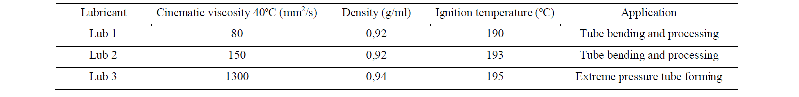
As mentioned before, three different mineral oils have been used in the study. The first two lubricants have low viscosity, 80 and 150 mm2/s respectively and they are typically used in the tube bending and forming of steel components. The third lubricant has a high viscosity, 1300 mm2/s, and it is typically used in extreme contact pressure applications and with critical components. All the lubricants have been produced by the same supplier using similar formulations and are compatible and highly soluble with the water-oil emulsion used in the hydroforming facility. Properties of the three lubricants are summarized in table 2.
Table 2. Properties of selected lubricants
3.2 Tube sliding test
The tube sliding test developed at Mondragon University is presented in Fig. 2. Like in [AHM00, HWA05, YI11] only one axial cylinder is employed for pushing the tube sample after the desired pressure level has been reached. Unlike with two axial cylinders, the use of one cylinder avoids the need of using a minimum axial force in both sides of the tube, needed for guarantying the sealing of the tube inner cavity. On the other hand, and because the axial pushing element is guided in bearings, the friction force can be directly measured using only one load sensor.
The configuration of the test is horizontal and was installed in the hydroforming cell that is available in the Mondragon University. The vertical force is measured in the upper side of the tool by the use of a load sensor that was manufactured using a 50CrV4 spring steel hardened at 56 HRc. A full Wheatstone bridge was used for the sensing of the new sensor and was calibrated using an universal compression machine. The upper side of the tool is guided using axial bearings to avoid any force loss caused by friction and acquire a precise measurement of the vertical reaction force. The hydraulic pressure intensifier and the axial cylinder are controlled using servo hydraulic valves of Bosch Rexroth and HNC100 electronic controllers.
Three different internal pressures, 20, 40 and 60 MPa have been used in the tests and two different sliding velocities have been evaluated, 0.5 mm/s and 5 mm/s. The tube yielding occurs approximately at 16 MPa and thus lower pressures are not testable with this tube material and thickness. The maximum pressure is just below the maximum hydroforming pressure that is needed to hydroform the selected component, 65 MPa. The sliding velocities were selected to cover the full range of typical velocities used for the hydroforming of different components. 5 g/m2 of lubricant was manually applied in the tubes using a brush and verified by a precision scale. The tool was cleaned using acetone after each test and before a new experimental condition was tested.
A typical test result is shown in Fig. 3. As it is observed, in the pressurization step the axial cylinder is static and only internal pressure increases progressively. At a certain pressure level, when tube yields, the pressure is transmitted in the form of vertical force to the vertical force sensor. After the pressure is in the desired test value, the tube is pushed by the axial cylinder, the sliding step starts and the axial force builds up. Note that in this step the vertical and axial force gradually increase. This effect was also observed by [AHM00, PRI 01b, PLA03, HWA05] and is attributed to the local thickening of the tube in the push rod area and to the progressive lubricant loss during the tube sliding.

Fig. 3. Different tool zones in tube hydroforming
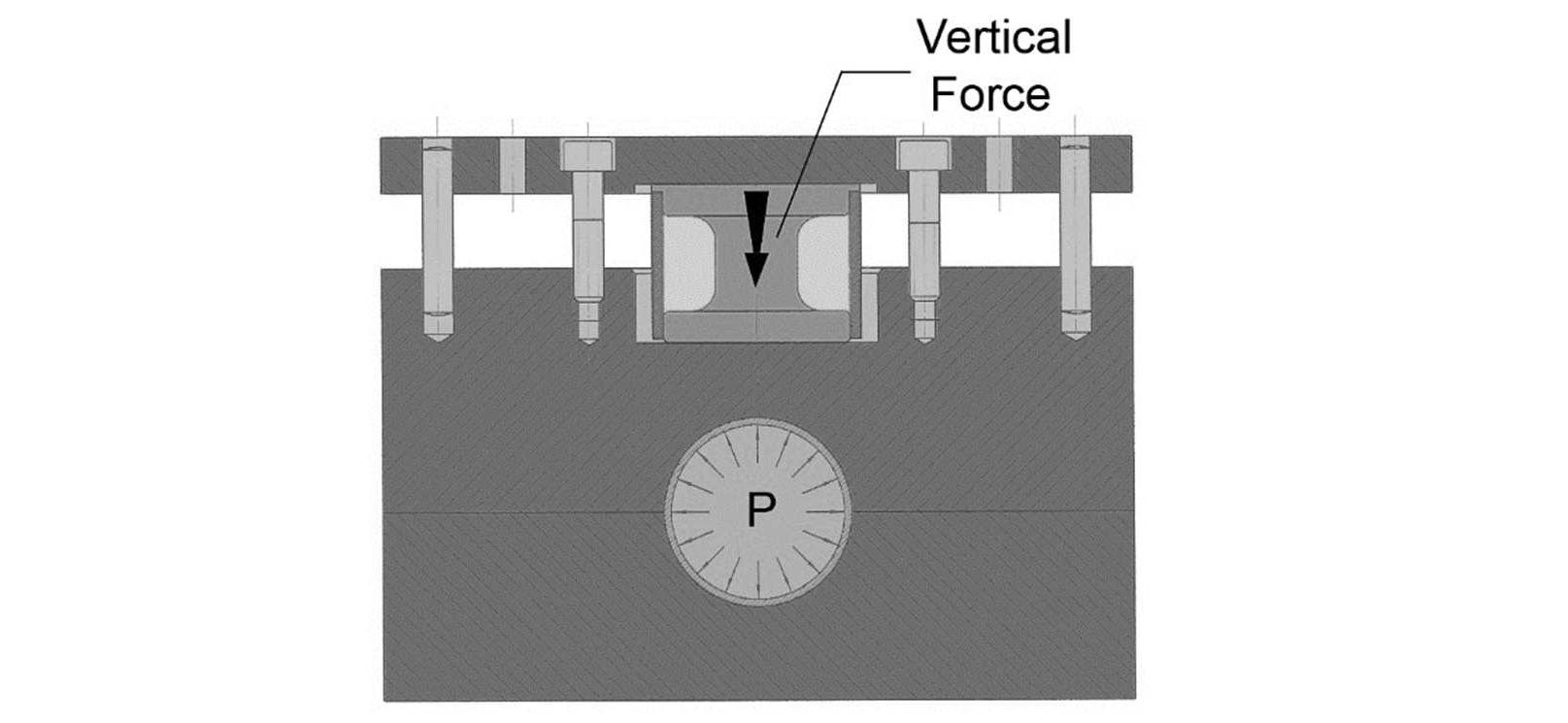
Fig. 4. Cross section of tube sliding tool
The friction coefficient can be easily calculated from the axial and vertical forces. The measured axial feeding force, Fa, for pressing the pushing rod is assumed to be equal to the friction force at the tube–die interface, thus the axial feeding force can be expressed as:

where P is the contact pressure, D is the tool diameter, and L is the tube length in contact with the die.
Similarly, the vertical force can be calculated by multiplying the contact pressure with the projected contact surface of the tubedie interface:

After the combination of the above formulae, the coefficient of friction is calculated as follows:

As the friction coefficient is not totally constant during all the sliding step, the average value is calculated from the evaluated feeding distance as suggested by [PLA03]. Three repetitions were made for all the conditions.
3.3 Experimental results. Fitting of variable friction laws
The experimental results for all the lubricants and tested conditions are shown in Fig 5a. As it is observed the maximum coefficient of friction is approximately 0.18 for the lubricant having the lowest viscosity and when tested in the lowest internal pressure and sliding velocity. On the contrary, the minimum friction coefficient is observed for the highest viscosity lubricant but the maximum sliding velocity, although small difference is observed in comparison to the lowest velocity of the same condition. The results clearly show that friction coefficient decreases when the contact pressure, the sliding velocity and the viscosity increase. The sliding velocity effect is less pronounced with the high viscosity lubricant and when contact pressure are high.
The experimental results have been fitted to a Filzek like friction law [FIL11]. The Coulomb friction coefficient depends on the contact pressure and the sliding velocity as follows:

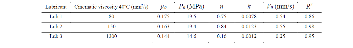
where μ0 is the reference coefficient of friction at the reference contact pressure P0, n is the pressure exponent defined within the range 0<n<1, k is the velocity factor that corrects the effect of the sliding velocity and Vrel and V0 are the sliding or relative velocity and the reference velocity respectively. The model parameters are summarized in table 3 and are plotted against the experimental friction values in Fig. 5b, Fig. 5c and Fig. 5d.
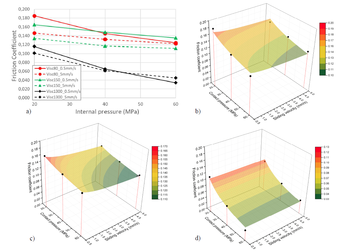
Fig. 5. Tube sliding friction test results. a) Experimental results at different conditions, b) fitted friction law for viscosity 80 lubricant, c) fitted friction law for viscosity 150 lubricant and d) fitted friction law for viscosity 1300 lubricant
Table 3. Filzek law parameters for the different lubricants
3.4 Surface micrographs of tested tubes
The initial outer surface micrograph of the tube before testing is shown in Fig. 6a. The typical EDT texturing pattern is present in the tube surface in order to optimize the contact behavior of the tube during forming processes.
After the tribological tests, the most damaged areas of the tube outer surfaces were selected for their evaluation. The 20 MPa micrographs showed that no change of external tube surface occurred when using the 1300 mm2/s viscosity lubricant. Flattening of initial asperities and plowing was observed for the low viscosity lubricants at the lowest internal pressure.
Fig. 6b and Fig. 6c are surface micrographs of highly damaged zones of tubes tested using 60 MPa of internal pressure, a sliding velocity of 0.5 mm/s and the two low viscosity lubricants. As in 20 MPa (not showed to avoid duplicity), flattening of initial asperities and deep plowing traces are observed for these cases. Most probably, the tribological condition is in the limit between the mixed and boundary lubrication regimes. The Fig. 6d shows the surface micrograph of a tube tested using the high viscosity lubricant at the same conditions. Flattening of asperities is observed in this case but not strong evidences of plowing are visible. This indicates that higher viscosity lubricant is able to limit the solid-to-solid macro contacts and thus justifies the low friction values obtained for this lubricant in the tube sliding tests.
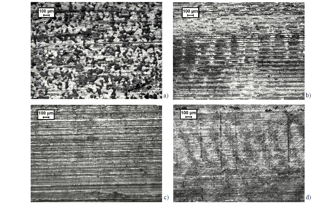
Fig. 6. Tube outer surface micrographs. a) initial tube before testing, b) micrograph of damaged zone for viscosity 80 lubricant, c micrograph of damaged zone for viscosity 150 lubricant and d) micrograph of damaged zone for viscosity 1300 lubricant
4 Discussion and Conclusions
Different authors have characterized the friction in tube hydroforming processes using tube-sliding test, tube upsetting tests and simulative hydroforming tests. Many different lubricants have been tested at different internal pressures and sliding velocities and their influence has been widely proved in the last two decades. In the present work the tube sliding method has been used to evaluate three different lubricants with three different viscosities, as it is the most straight forward available test and is optimal for the feeding zone friction characterization, the most critical zone for the numerical simulation of hydroforming processes with axial feeding of material.
The experimental results showed the lower the viscosity the higher the friction coefficient is. Similarly, the friction increased when the contact pressure and the sliding velocity decreased. The experimental friction coefficients are in good agreement with other available publications. Friction values between 0.04 and 0.22 were reported in [KOÇ03] for four different type of lubricants. The friction coefficients were obtained using inverse simulation and minimizing the error between the experimental and numerical thickness distribution predictions. Ngaile et al. predicted friction values between 0.075 and 0.125 for four different solid like lubricants. Schuler recommended the use of friction coefficients between 0.25 and 0.38 for oils [PRI 01b]. These friction coefficients are slightly higher than the ones obtained in this work although the same authors reported much lower friction values using the same testing facility and other lubricants [PRI99, GRO05]. Plancak et al. reported friction values between 0.004 and 0.07 by using the tube upsetting method [PLA03, PLA05]. Same authors used the tube-sliding test to obtain friction coefficients of the guiding zones and reported values from 0.025 to 0.15 for mineral oils [VOL02]. These last values are in good agreement with the friction coefficients obtained in the current work and indicates that tube upsetting test predicts much lower values than the tubesliding test. This can be explained because the flattening of asperities is very pronounced in the tube upsetting test (tube axial compression and hydrostatic pressure acting at the same time) and the local relative material movement is very small. Hwang et al. reported a friction value of 0.045 for a mineral oil using the tube-sliding test. The friction is quite low in comparison to our study but soft aluminum tubes were tested and both the tube outer surface roughness and tool roughness were higher [HWA05]. More recently, two research groups reported values of 0.22 in [FIO13] and from 0.01 to 0.09 in [YI11] for different mineral oils.
The friction coefficient dependency with the contact pressure is similar for all the tested lubricants, although the low viscosity lubricants show a slightly smaller reduction slope in comparison to the high viscosity lubricant (see Fig. 5a). In general, the sensitivity of the coefficient of friction to the sliding velocity is higher in the low viscosity lubricants. This may be explained because with these lubricants the tribological system is in the limit of boundary and mixed lubrication regimes and solid-to-solid contact is higher than in the high viscosity case. In these conditions, surface flattening may be higher than in the case of the high viscosity lubricant, which is near the hydrodynamic regime.
A Filzek like analytical friction coefficient law has been successfully used for the fitting of the experimental data. In general, the model shows a good agreement with the experimental values and the minimum R-squared (R2) is 0.86. As explained before the highest viscosity lubricant has the highest sensitivity to the contact pressure and this is reflected in a lower pressure exponent n. Similarly, the medium lubricant has the higher sliding velocity dependency and this is shown in the model parameters, where the maximum k value is observed for this case.
Regarding the outer surface micrographs, flattening of initial asperities is observed for all the lubricants at high contact pressures. Only the high viscosity lubricant at low pressures showed no flattening of initial EDT texture. Deep plowing traces are observed for the low viscosity lubricants indicating that lubrication regime is in mixed lubrication regime and not far from the boundary regime. On the contrary, the high viscosity lubricant tribosystem is in the mixed lubrication regime but some condition may indicate we are near the hydrodynamic regime, especially at low pressures.
The new friction variable models will be used in the near future to simulate the hydroforming of a triangular shape component with a perimeter expansion of 40% and big axial feeding of material. Numerical and experimental results will be compared for models validation and to quantify the effect of the new models against a classical contact friction model.
