1 Introduction
Recent efficiency enhancement in the aerospace and general aviation sectors are mainly due to developments in the material science/technology field. Modern high-performance materials, such as nickel-based alloys, are constantly improved to manifest higher resistance to cyclic thermo-mechanical loads and oxidation, in order to operate under elevated temperatures for prolonged periods of time. In particular, among these alloys, stands out Waspaloy, for its even superior performances [1, 2].
Traditional machining processes involve the removal of material from a workpiece, which generates chips and produces a new surface on the workpiece, involving large strain fields and intense heat generation. These phenomena allow to account machining as a local severe plastic deformation process, implicating substantial effects on the final product surface integrity. Its improvement, opportunely setting the machining parameters and lubri-cooling conditions, is of fundamental importance to manufacture products of higher performances and affordability, avoiding potential surface defects that can lead to their failure [3].
Optimizing the processing parameters and developing engineered surfaces that can lead to these superior performances involve extensive use of computational and simulation methods, allowing to predict the process variables of industrial interest (machining forces and temperatures) and the final microstructural surface changes (grain refinement, hardness increment, etc.) [4].
In machining simulation, a proper imitation of the material plastic behavior plays a fundamental role in order to properly simulate the machining process. Thus, many simulation techniques and methods have been developed to mathematically modeling the plastic flow stress. In this contest, two different techniques show up, phenomenological models and physics based models [5]. The first ones are based on direct observation of the plastic flow phenomena with a direct interpolation of the measured stress values function of the deformation conditions, building up a mathematical interpolation of experimental results. This makes them particularly simple to be implemented in a software. On the other hand, they frequently need to be re-tuned considering differences from calibration conditions to simulations. Moreover, These models are not able to give any information about the metallurgical changes occurring on the processed material, obligating the simulator to implement aside models to obtain these information [6]. Conversely, physics based models provide many information concerning the physical/microstructural evolution of the processed material and are easily adaptable to different bulk material metallurgical conditions, though they are extremely difficult to be implemented, resulting in a more time consuming implementation phase [7].
In the presented research work, a benchmark among different rheological models for machining simulation is presented. More in detail, different numerical models were considered. All the results obtained from the numerical simulations were compared with experimental results, aiming to quantify their prediction capabilities and their efficiency in the mechanical and surface integrity based design phase of an industrial machining process.
2 Experimental Procedure
The orthogonal dry machining tests, were conducted on a MAZAK high speed CNC turning center. Three different cutting speeds (40, 55, 70 m/min) and feed rates (0.05, 0.10 and 0.15 mm/rev) were used and four repetitions of each experimental case study were performed. It is worth to point out that the experiments at 0.15 mm/rev were considered only for the speed of 40 m/min, because of the premature machining tool failure induced by excessive wear rate at the cutting speeds of 55 and 70 m/min [8].
The experimental tests consisted in radial facing operations of Waspaloy (45 HRC), tests were performed using S quality rhomboidal 55° coated carbide tool (edge radius of 18 μm), mounted on a DDJNR 2525M 15 tool holder (provided by Sandvik Coromant©). The latter was fixed on a piezoelectric dynamometer (Kistler© 9257), in order to measure the cutting forces. Temperatures on the side of the tool-chip interface were also measured during the machining tests via IR thermo-camera provided by FLIR (A6000-series). Finally, all the samples were sectioned, mounted, polished and etched to carry out metallographic and microhardness analysis. The etchant employed was the Kalling's reagent that is recommended for aged and solution treated material. The microstructure of the worked samples was analyzed using optical microscope (Leica© DFC320 1000×). The microhardness (HV0.01) was measured on polished samples using a QNES10 micro-indenter for 10s of pause time. Further details about the experimental trials are described in previous works [8, 9].
3 Finite Element Numerical Model
A Finite Element physics-based model of the orthogonal cutting process has been developed using the commercial software SFTC Deform2D®. A plane-strain thermo-mechanical analysis was performed via Update-Lagrangian code involving a solid remeshing technique. The workpiece was meshed with 20000 isoparametric quadrilateral elements, with a severe mesh refining near the cutting zone, having here a mean element size of 2 μm. The tool has been modelled in the FE software as a rigid body and the geometry has been obtained studying the cutting tool using a ConScan Surface Profilometer. The surface contact behavior at the tool-workpiece interface was modelled by implementing the hybrid friction model in order to take into account both the effects of sticking and sliding at tool-chip interface using, while the global heat transfer coefficient (hint) at the tool-workpiece interface was set equal to 105 kW/(m2K) according to the guidelines and literature results. The values of the friction constants were considered using the friction model proposed in [9] obtained and then refined by a calibration procedure in the cutting parameters range of the experimental tests.
4 Plastic Flow Stress Models
Afterwards a broad literature analysis, four rheological models were chosen for the benchmark that account both the different simulation techniques (phenomenological and physics based models). The first model is a physics based model presented by the authors in a previous work [9]. The second one is a Johnson-Cook (JC) model proposed by Dong et al [10]. The subsequent model was developed by Caruso et al [11] opportunely modifying the common JC flow stress model to better consider the material deformation strengthening effects. The last one is a new JC model proposed for this research work. All models will be detailed below in subparagraphs.
4.1 Model 1 – Physics Based Model
The proposed physics based model assumes the flow stress (σ) as the algebraic linear sum of the contributions of the different microstructural phenomena occurring during plastic deformation processes (Eq. 1).

where 𝜎∗ is the Peierls Stress and is thermally activated. 𝜎𝐺 denotes the long range strengthening induced by dislocation accumulation, and 𝜎𝐻𝑃 is the Hall-Petch stress.
The interaction between the mobile and immobile dislocations is the physical basis of the strengthening of a general metal material and is described by the well-known Taylor equation (Eq. 2).

Where 𝛼𝐺 is a proportional constant, M is the Taylor factor, ρi is the density of immobile dislocations, G is the temperature dependent shear modulus and b is the Burger’s vector.
The evolution of the dislocation is described by the two terms of Eq. 3. In detail, 𝜌̇𝑖(+) represents the material strengthening due to the dislocation accumulation, while 𝜌̇𝑖(−) represents the material softening due to the recovery effects.

The motion of the dislocation can be obstructed by the presence of lattice obstacles causing a strengthening effect in the material flow stress. This phenomenon is described by Eq. 4.

Where 𝜀̅̇𝑝 is the equivalent plastic strain rate, D is the initial grain size, Kc is a calibration constant, and the ratio 𝐾𝑐/√𝜌𝑖 represents the crystal cell size.
The material softening due to the recovery effect is described by Eq. 5.

Where Ω is the recovery function.
The mean grain size D was predicted considering the common mixture law (Eq. 6):

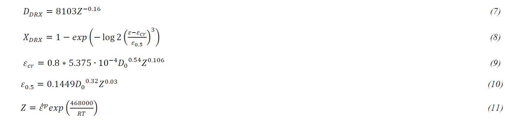
Where D0 is the average initial grain size (41 μm), DDRX is the dynamically recrystallized grain size (Eq. 7) and XDRX is the volume fraction of the recrystallized grains (Eq. 8) [11, 12]. It depends on strain (ε), critical strain (εcr) described by Eq. 9 and ε0.5 by Eq. 10, that is the strain referred to the 50% of recrystallized microstructure and both depend on Zener-Hollomon Parameter (Eq. 11).
Where T is the absolute temperature and R is the universal gas constant. The 𝜎𝑡ℎ term represents the lattice stress and is described by Eq. 12.

Where 𝜏0 is the frictional shear stress, Δ𝑓0, q and p are calibration parameter, 𝑘𝑏 is the Boltzmann constant, and 𝜀̇𝑟𝑒𝑓 is the reference strain rate.
The strengthening induced by machining operations on the material can be modelled as suggested by Eq. 13:

Where kh is a calibrated material constant.
The whole model described by Equations from 1 to 13 is taken from the work of Imbrogno et al, where is possible to find more details about the values of the constants and the microstructural effects predictable by the model are deeply described [12].
4.2 Model 2 – JC Model
The second model considered for the benchmark is the JC model used by Dong et al to study Waspaloy small diameter internal thread induced tool wear. It is formulated as shown in Eq. 14.

Where the first coefficient (A) represents the material yield stress at room temperature, which can be directly obtained from simple quasi-static tensile or compression. Similarly, the coefficient (ε̇0) indicates a reference strain rate, which can also be obtained directly from the same tests, while Tm is the material melting temperature and Tr is the environment temperature relieved on the deformed workpiece. The other coefficients B, C, m and n, are calibration constants which depends on the material behavior, and do not have a direct physical meaning [13]. The values of the model constants are reported in Table 1.
4.3 Model 3 – Modified JC Model
The third model was proposed by Caruso et al to study Waspaloy surface modifications induced by machining process. This model is basically a modified JC that also takes into account the Hall-Petch strengthening phenomenon (Eq. 15). Indeed, the A coefficient of Eq. 14 is modified as shown in equation below (Eq. 16) to take into account the material Hall-Petch strengthening induced by dynamically recrystallization induced grain refinement effects.
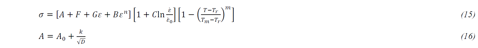
The grain size (D) is computed using the same simulation strategy employed for Model 1, while F, G, A0 and k are material constants. The values of Model 3 constants are reported in Table 1.
4.4 Model 4 – NN JC Model
Model 4 is the new JC model proposed for this work. To obtain this model an Artificial Neural Network (ANN) based fitting procedure was considered. A large number of FE orthogonal machining virtual experiment were conducted. The latter were based on the simulation procedure described in Paragraph 3 and they were conducted varying the cutting parameters (cutting speed and feed rate) within the range of the experimental plan. The five JC constants (Eq. 14) were also varied in each one of the FE simulations in order to understand their influence on the simulation results. The cutting forces and the machining temperatures were also measured for each virtual experiment. In particular, the process parameters and JC constants for the virtual experiments were set on the basis of a specific Design of Computer Experiments.
An ANN fitting procedure was developed on three layers (input, hidden and output levels) setting the backpropagation methodology. In particular, the specific predefined module of the commercial software MATLAB was used, according with the software guidelines [14]. The virtual experiments were exploited for the ANN training, allowing the latter to reproduce with sufficient accuracy the virtual experiment results, more in detail the cutting parameters and the JC constants were set as input, while cutting forces and temperatures were taken as output for the ANN training procedure. Finally, the cutting parameters used to conduct the real experimental tests were set as input to the trained network, while the experimentally measured forces and temperatures were fixed as output. In this context, the trained ANN could give the values of the A, B, C, n and m constant that better relate the input parameters with the output results, the obtained constants are reported in Table 1. For a more detailed description of the ANN fitting procedure, the reader is remanded to the work of Franchi et al [15].
Table 1 Summary of the values of the JC Constants for JC benchmarked models

5 Results and Discussion
5.1 Cutting Forces and Temperatures
Fig. 1a and Fig. 1b show the values of the simulated steady state Cutting Forces (Fc) and Thrust Forces (Ft) for all the investigated rheological models compared with the experimental results, while in Fig. 1c the comparison among the relieved machining temperatures is reported. It is worth noting that, the best approximation of machining forces is given by Model 1 with a mean absolute error of 5% and 9% for cutting and thrust forces, respectively. Concerning the machining forces predicted using Model 2, the mean absolute error is extremely larger, with values of around 68% and 66% for cutting and thrust forces, respectively. This large error is attributed to the model interpolation. Specifically, the rheological model was developed for strain condition quite different from the machining conditions studied, where the occurrence of metallurgical modifications tends to hugely modify the plastic behavior of the material. Indeed, Model 3 took into account the microstructural modifications occurring during the machining process, and consequently the founded mean absolute error is consistent, but it is underneath respect to the previous model, with the values of 31% and 13% cutting and thrust forces, respectively. Finally, the proposed rheological model (Model 4) shows an even lower error of 9% and 21% for cutting and thrust forces, respectively.
For what concerns the relieved temperatures at the tool-workpiece interface, Model 2 shows a very large mean absolute error of around 60%, while Model 1, Model 3 and Model 4 better reproduce the experimental results, with an overall mean absolute error of 7%, 17% and 4 %, respectively.
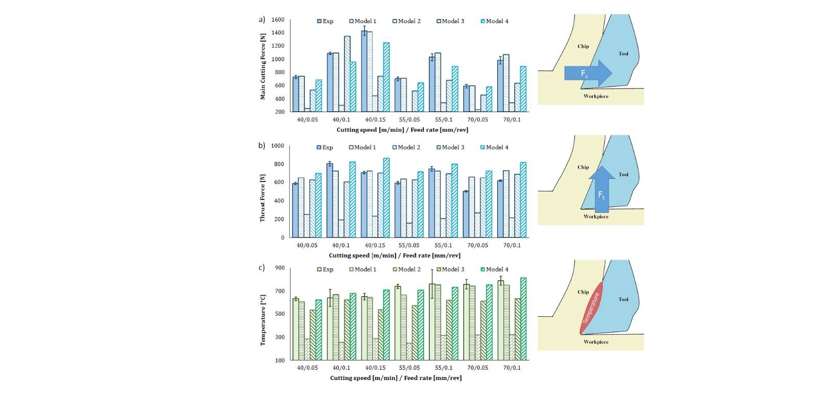
Fig. 1 Comparison among the experimental measurements and the FE simulated results for Main Cutting Force (a), Thrust Force (b) and Machining Temperatures (c)
5.2 Microstructural Modifications
On the processed surface (Fig. 2b), the machined zones show intense slip activity and act as preferred site for grains nucleation, causing dynamic recrystallization (DRX). Similarly, in the machined chip serration zones is possible to identify an area of intense plastic deformation where the most significant metallurgical modifications occur (slip activity, DRX) in the adiabatic shear bands, while, away from the bands, it is possible to notice areas of rigid motion resulting in a slightly deformed zone (Fig. 2a). Concerning the grain variation spectra below the machined surface, it is possible to notice that Model 1 correctly reproduce the grain refinement layer (Fig. 2c), as also reported in [12, 16], while Model 2 does not show any DRX phenomena, due to the lower temperature developed that cannot allow to overcome the triggering threshold imposed by the critical strain (Fig. 2d). Concerning Model 3 and Model 4 (Fig. 2e and Fig. 2f respectively), on a qualitative analysis they both predict the grain refinement layer in a proper manner, but Model 4 show a more homogeneous layer thickness.
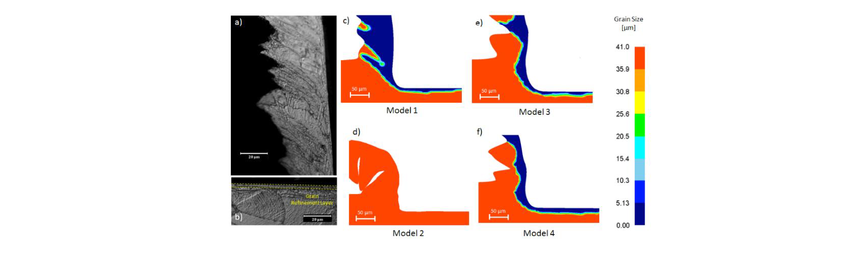
Fig. 2 Experimentally relieved machined Chip (a) and surface (b), and numerically predicted microstructural modifications by Model 1 (c), Model 2 (d), Model 3 (e) and Model 4 (f)
5.3 Surface and Subsurface Hardness
Concerning the predicted surface microhardness (Fig. 3a), Model 1 is in good agreement with the experimental results with a mean absolute error of around 4%, as also reported in [12]. Similarly, Model 4 shows a good prediction capability, with a similar mean absolute error, while Model 3 shows a slightly higher mean absolute error of around 5%. In particular, Model 1 tends to overestimate the error, while Model 3 and Model 4 tend to underestimate it. Moreover, due to its low strengthening capacity, Model 2 shows the larger mean absolute error (8.20%), heavily underestimating the surface hardness.
For what concern the prediction of the subsurface hardened layer, the predicted results are visible in Fig. 3b at the cutting parameters of 70 m/min and 0.10 mm/rev, taken as representative example of the overall results, the predicted values tend to follow this trend. Along the machined subsurface layer, Model 1 and Model 4 show an extremely good match with the experimental results, demonstrating a similar behavior and with slight differences in terms of approximation error. Model 3 shows a slightly higher error along the depth, while Model 2 reports the larger approximation error relieved.

Fig. 3 Experimentally relieved machined surface (a) and subsurface (b) microhardness
6 Conclusions
In this work, a benchmark among different rheological models used to simulate Waspaloy orthogonal machining is presented. The predicted variables of industrial interest and the simulated microstructural modifications are compared to evaluate the capabilities of the different models. Globally, physics based model (Model 1) results to be the one that best fit the material behavior under machining conditions, depending on its dependence from the physics phenomena occurring during deformation, it demonstrates more robustness under largely different process conditions. On the other hand, this model results to be extremely difficult to be calibrated and implemented in a FE software. Model 2 was calibrated in deformation conditions extremely different from the simulate ones, indeed its simulation capacities results to be very weak under the analyzed machining conditions. Moreover, the model shows a very low strengthening effect, consequently its prediction capabilities tends to largely underestimate all the variables that depends on it, such as cutting forces, temperatures and surface hardness. For what concerns Model 3, its parameters are not so different from Model 2, however it shows very lower errors in the prediction of the experimental results. Its dependence from microstructural modifications make it more versatile, confirming that a rheological model depending, at least in part, from physics phenomena results to be more functional. Finally, the proposed model (Model 4) is the phenomenological model that shows the lower prediction errors. However, this model was calibrated under the specific cutting parameters that are object of analysis, consequently, although it shows extremely good prediction capabilities.
In essence, the best approximation of the experimental results is obtained when the physical effects are considered in the model build up procedure, while the employment of phenomenological models is function of the interpolation conditions and prediction capacities may vary when simulated process parameters and tuning conditions are too different. Indeed, the fitting of the experimental results tends to improve when the microstructural modifications are considered into the rheological model.
