1. Introduction
Finite element simulation of thin sheet metal structures has played an incredible role in product design and manufacture processes. Quantitative analyses of accuracy of numerical results show that the selection of a proper element plays a vital role in the accuracy and efficiency of the simulation, in particular, the complicated ones, such as sheet metal forming. Recently, considerable effort has been devoted to the development of solid-shell finite elements [1, 2, 3]. They combine the advantages of the traditional solid and shell elements since they are three dimensional displacement/velocity based elements with reduced integration and enhanced strain fields. In this work, one of the solid-shell elements family (SHB) is presented. A prismatic element is selected as it can be integrated into our selected software FORGE. In this paper, the basic formulation of the SHB element is presented in section(2). Also, numerical implementation is discussed in section(3). Then, results of the application of Magnetic Pulse Forming (MPF) process will be presented in section(4). Finally, the prospective of the current and future work is discussed in section(5) which includes anisotropic yield criteria and remeshing.
2. Formulation of the SHB solid-shell elements
In this section, the general formulation of the SHB solid-shell element family will be briefly discussed. The detailedformulation can be found in many resources [4, 5].
The geometry and location of the integration points for different types of this element are presented in Figure (1). The element is designed in such a way that the direction ζ is aligned in the thickness direction of the structure. Usually, for large strain and plasticity problem, such as metal forming, the number of integration points in the thickness direction is chosen to be five [4].
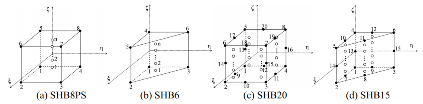 Figure 1: Geometry and location of integration points for SHB elements: (a) linear prismatic element SHB6 (b) linear hexahedral element SHB8PS (c)
quadratic prismatic element SHB15 (d) quadratic hexahedral element SHB20.
The SHB solid-shell elements are based on a 3D approach using the classical isoparametric linear and quadratic shape functions. The interpolation of the coordinates xi and the displacements ui is as follows:

where NI, diI and xiI are the shape functions, the nodal displacements and the nodal coordinates respectively. Also, the lowercase subscript i varies from 1 to 3 representing the spatial coordinates; the uppercase subscript I varies from 1 to n, representing the number of elements nodes.
The discrete gradient operator B defining the relationship between the strain field 𝜵s(u) and the nodal displacement field d is given by:

The assumed-strain method used in the formulation of the SHB elements is based on the simplified form of HuWashizu principle introduced by Simo and Hughes in [6].

where δ denotes a variation, ε ̇ the assumed-strain rate, σ the stress field, v the nodal velocities, and fext the external nodal forces. The assumed-strain rate ε ̇ , represented by a six-component vector is expressed in terms of a B matrix, projected from the classical discrete gradient B defined by:

The projected assumed strain matrix B(x) is used to alleviate the locking problem by manipulating some of the shear components of strain tensor [7].

B1 contains the components corresponding to the normal strains, while B2 contains the components corresponding to the shear strains and ω is scaling factor. The full expressions for B is in [7]. Inserting Eq.(5) in the variational principle Eq.(4). The element stiffness matrix and force vector can be defined:

Cep is the elastic-plastic tangent modulus associated with the material behavior law.
3. Numerical implementation
Although the SHB element family has been implemented in previous work of [1, 4, 5, 7, 8], the implementation was always straight forward using element shape that is compatible with the proposed element formulation. On contrary, the work done in this paper is based on the simulation software FORGE which is genuinely based on tetrahedral element shape. In a general way, the proposed strategy allows to decompose the SHB element into a set of simplified elements. This technique could be used with libraries that present limitations on the topology of elements that are supplied. Taking that into consideration, the implementation of the proposed prismatic element in FORGE is considered to be the most challenging part of the current work, in particular when it comes to work with parallel processing. In the following section, the implementation technique will be summarized.
3.1. Prism division concept
Since one of the main privileges for modelling forming processes with FORGE is the use of tetrahedral element, it would be difficult to keep the same efficiency with the implementation of a new geometrical element shape. Therefore, the idea of dividing one prism element into six overlapping tetrahedral element would be an efficient way to solve this problem. The overlapping of elements is crucial so that all the components of the original SHB stiffness matrix could be presented in at least one of the generated tetrahedral elements.
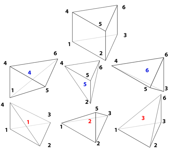 Figure 2: Prism division to 6 overlapping tetrahedral elements.
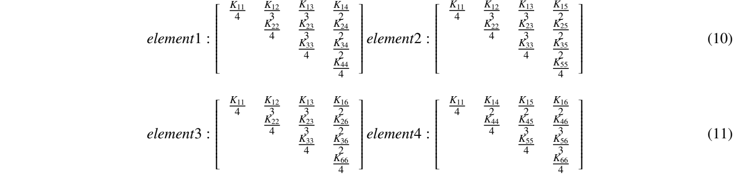
Figure (2) shows the corresponding tetrahedral elements generated from the divided prism element. Considering the number of tetra elements sharing each component(node) of the prism stiffness matrix, the new stiffness matrices for the tetra elements can be constructed as follows:

In this way, the prism element was modelled implicitly through the use of tetrahedral elements and all subroutines and modules of FORGE were used perfectly.
4. Simulation of magnetic pulse forming (MPF)
In this section, the efficiency and accuracy of SHB element, implemented in FORGE, is evaluated by analyzing complex sheet metal forming process. This problem includes geometric and material non-linearities. The results are compared to the results of the original element of FORGE (MINI) [9] along with experimental results.
4.1 Background on magnetic pulse forming process
The main operating principle of MPF process is based on electromagnetic interactions, which can be modelled by Maxwell equations. First, the energy input coming from the main is stored in the machine by utilizing large capacitors. These capacitors release the stored energy in the form of a pulse wave that can reach (100 kA). Then, the current coming from the capacitors passes through a coil that creates an intense magnetic field around itself. The workpiece is placed very close to the coil so that the varying magnetic field induces a current in the workpiece(eddy current). Finally, the conjunction between the eddy current and the magnetic induction field creates Lorentz forces according to equations (13,14,15)

F : lorentz forces

|
J : current density, σ : electrical conductivity and E : electrical field
|

B : magnetic induction field, H : magnetic field, µr : magnetic permeability of the material, µ0 : magnetic constant, ε0 : permitivity of the vacuum and c : speed of light
Lorentz forces are responsible of the plastic deformation of the workpiece. It is projected in the opposite direction of the coil, on a matrix which has usually the final shape. Thus, it is possible to carry out different types of forming depending on the location of the coil with respect to the workpiece. For instance, we can increase the radius of a pipe if the coil is located inside the pipe; this is called MPF by expansion. We can also decrease the pipe radius, by compression.
More theoretical and mathematical details on the MPF process can be found in ([10],[11]).
4.2. Description of finite element model
Figure (3) shows the schematic view of the free bulging process. A round flat coil is used along with a ring-shaped matrix that blocks the displacement at the circumference of the workpiece. Regarding the numerical model, a specific development version of the Forge software has been used in order to simulate electromagnetism phenomenon. Thus, a coupling between an electromagnetic solver and a mechanical solver is performed to reproduce conditions similar to the real physics. Due to the symmetric nature of the problem, only a 2◦ section is being considered for the simulation to reduce the total simulation time. The following subsections will tackle the details of the simulation setup with respect to the electromagnetic simulation and the mechanical simulation.
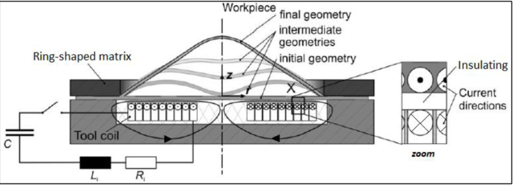 Figure 3: Illustration of magnetic pulse forming setup
4.2.1 Electromagnetic simulation setup
Geometry : Figure (4) shows the geometry of the electromagnetic simulation with the dimensions noted on it. The thickness of the aluminum used is 1 mm and is located 0.5 mm above the coil.
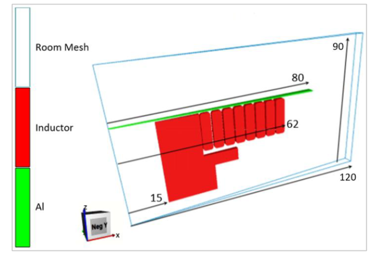 Figure 4: Geometry and dimensions of the electromagnetic simulation
Mesh : Figure (5) shows the mesh used in the electromagnetic simulation. 3D global mesh is composed of (43,000 nodes with 260,000 tetrahedral elements. Coarse mesh is used in the areas that are not important in the simulation while finer mesh is used around the coil and the workpiece to get accurate results. Mesh adaptation of the global mesh is activated to follow the deformation of the workpiece.
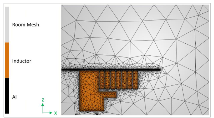
Figure 5: Mesh configuration of the electromagnetic simulation
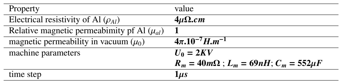
Simulation properties : Table (1) shows the magnetic properties of the material according to equations (14,15), used in the simulation along with the parameter of the machine used in the MPF process.
Table 1: Properties of the electromagnetic simulation
4.2.2. Mechanical simulation setup
Geometry : Figure (6) shows the geometry of the 2◦ section of the workpiece. The workpiece is fixed in the region of the green ring shown in the figure.
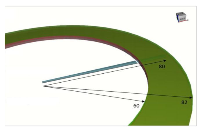
Figure 6: Geometry and dimensions of the mechanical simulation
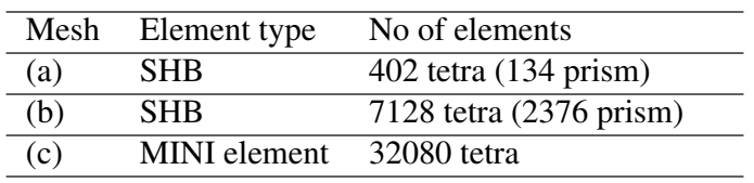
Mesh : Three meshes have been used to simulate the mechanical problem and the results were compared. First, coarse prism mesh divided into tetrahedral elements 1 shown in figure (7.a). Second, more refined prism element shown in figure (7.b) and finally, very fine unstructured tetrahedral mesh used for (MINI element) of Forge shown in figure (7.c). The number of elements used in each mesh is summarized in table(2)

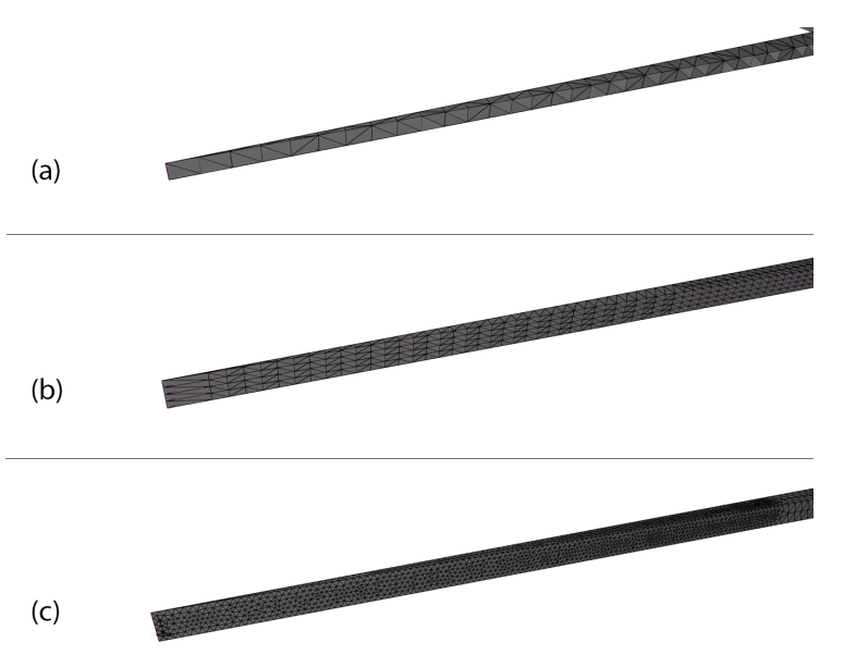 Figure 7: (a) coarse prism mesh, (b) fine prism mesh, (c) fine tetra (MINI element) mesh
Table 2: Number of elements used in each of the meshes used in the mechanical simulation
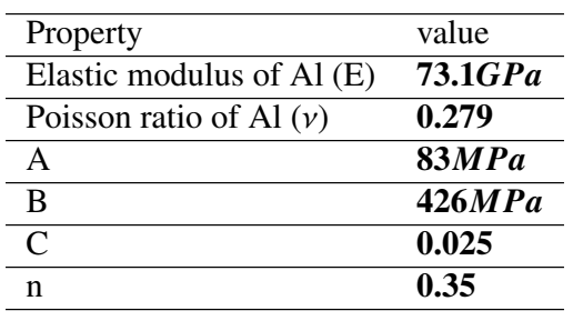
Simulation properties : Elastic properties for Al used in the simulation are shown in table(3). On the other hand, Johnson-Cook law was used to describe the elastoviscoplastic behaviour of the material. Equations (16) shows the behaviour law used and table(3) shows the corresponding constants. Finally, the simulation time was set to 150µs with a time step of 1µs.

Table 3: Elastic properties of Al and Johnson-Cook law parameters
4.3 Results and discussion
This section tackles the results obtained from the simulation of MPF process along with some experimental results. The results will be divided into results related to the electromagnetic simulation and results related to the mechanical simulation. Though, the main focus will be on the mechanical results in which the SHB element will be tested. Quantitative comparisons between the standard element (MINI) and SHB element will be presented. The results will be assessed in terms of the accuracy with respect to experimental results and time of simulation.
4.3.1. Electromagnetic simulation results
In this subsection, the results of the induced current in the workpiece at 2 kV potential are presented along with the generated Lorentz force due to the magnetic field applied on the part. Figures (8) and (9) show the induced current and Lorentz forces in the workpiece respectively. It can be noticed that Lorentz forces depend on the electric current density J and the magnetic induction field B. The area where the Lorentz forces are maximum is the area where the penetration of the electromagnetic wave is maximum. Lorentz forces are maximum at the start of the process and tend to decrease as the part moves away from the coil and only the first peak current generates maximum forces.
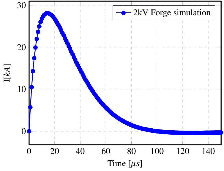
Figure 8: Induced current in workpiece at 2kV
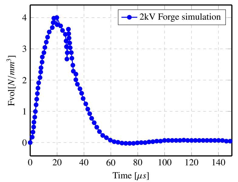 Figure 9: Normal component of Lorentz forces
4.3.2 Mechanical simulation results
In the this section, quantitative comparison between experimental and numerical results will be presented. For the experimental tests, we used a magnetic pulse forming machine from CEMEF. The machine consists of three main blocks: A control panel allows you to define the desired input potential. In this panel, an electric transformer is installed to convert the electric current coming from the plug in into a high voltage signal to charge the capacitors. The capacitor bank which is currently made up of 12 capacitors of 46 µF each. The workstation which is equipped with a pancake-shaped coil. In the experimental results, it is noted that the displacement is maximum at the center of the workpiece. Though, the shaped part is not symmetrical since the coil is not perfectly symmetrical. Figure (10.a) shows the deformed shape of the part under 2 kV applied potential.
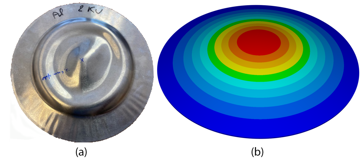
Figure 10: Deformed shape of the workpiece under 2kV applied potential; (a) experimental (b) numerical
For the numerical results, the maximum displacement is always at the centre point. However, the deformation is always symmetric refer to figure (10.b). A comparative study has been carried out between the displacement evolution of the centre point with time for MINI element, SHB with coarse mesh and SHB with fine mesh. Figure (11) shows the displacement curves for the three elements. From the figure, it can been noticed that MINI element is over estimating the deformation although many elements have been used. On the other hand, the results of both SHB with coarse mesh and fine mesh are very close and under estimating the displacement. Moreover, there is a small difference between the deformation evolution between MINI ans SHB elements at the very beginning. It is hard to judge which one of them is more realistic than the other since we do not have any information about the experimental deformation evolution through time but we only have the final deformation.
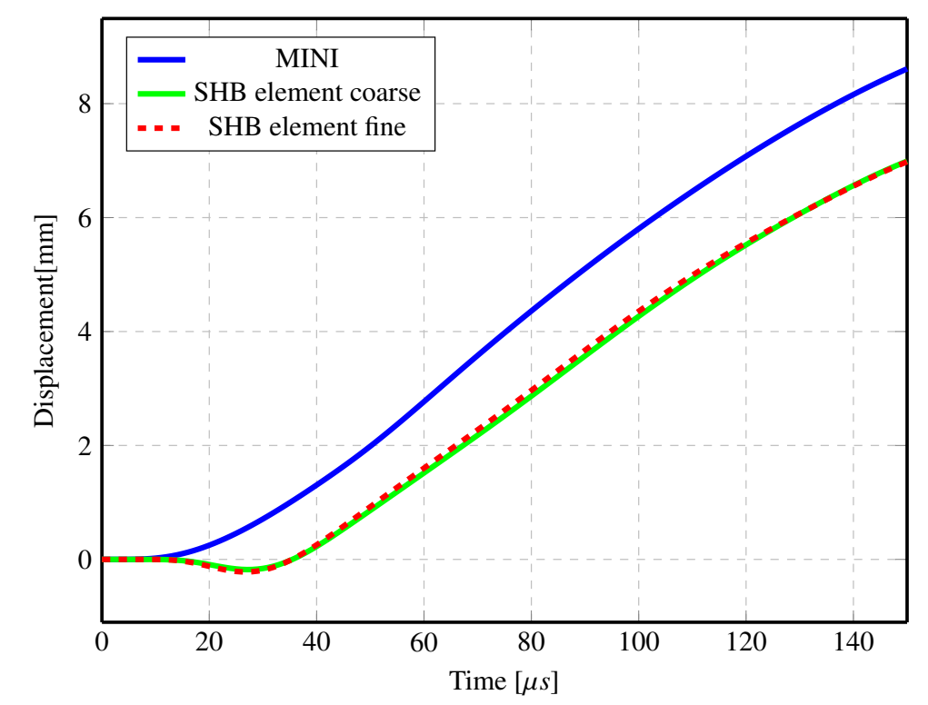 Figure 11: Displacement of the centre point of the wokpiece
In order to have an objective comparison, the final displacements of the simulation are compared to experimental ones. Table(4) shows the numerical value of the center point deformation. From the table it can be noticed that both of SHB elements coarse and fine meshes are more accurate than their counterpart MINI element. The relative error of SHB element is < 3% while MINI element has relative error ≈ 20%. These results are very encouraging to use SHB element in the applications of MPF.
Table 4: Numerical value of the centre point displacement

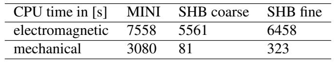
Finally, the computational cost of each simulation has been measured to make a better performance assessment. Table(5) shows the corresponding CPU time2 for each element for both of electromagnetic and mechanical simulations. The overall results show that SHB is very efficient computational wise and even using a coarse mesh does not deteriorate the results with respect to the finner mesh. Consequently, the overall performance of SHB element in such application is really satisfactory.
Table 5: Computation details of magnetic pulse forming process
5. Prospective and Future Work
In this section, the prospective of the ongoing work along with future work will be discussed in brief. Currently, anisotropic yield criteria have been developed in external library called MPCP at CEMEF. The aim afterward is to solve MPF with anisotropic yield criteria and notice the change in the results. This comes in handy with the fact that the workpiece used in MPF is very thin and might inherit anisotropic plastic behaviour. Moreover, the work on remeshing process for SHB element in going in full swing. The main idea is to try to utilize remeshing features of Forge and apply them on the new element. This is expected to improve the efficiency of the code as the simulation could be started with coarse mesh and mesh is refined when needed by the remesher. The newly developed featurs are supposed to be implemented and tested with benchmark problems whether MPF or other problems.
6. Conclusion
In this paper, linear prismatic solid-shell (SHB) element has been used in the application of magnetic pulse forming. The resulting element formulation was implemented in finite element software FORGE which is based on tetrahedral element (MINI). The compatibility issues were resolved by means of prism division technique to introduce the prism element as a combination of tetrahedral elements to be able to utilize all the subroutines available in FORGE. The performance of the proposed element was assessed by simulating the MPF process. The obtained results from SHB element were compared to its counterpart MINI element originally implemented in FORGE. Also the numerical results were compared to experimental results carried out in CEMEF. The overall results show that SHB element is relatively more accurate than MINI element even when using very low number of elements. The comparison between using SHB element with a coarse mesh and fine mesh showed minute change in the results which implies that a coarse mesh can be used without deteriorating the results. Finally, a computational cost study was carried out and showed that SHB element is much more computationally efficient. These results are very encouraging to keep studying the performance of SHB element in MPF application or other applications.

