1 Introduction
Due to the lack of raw materials and the challenge to reduce the green house gases the demand to develop lightweight products and related efficient manufacturing process increases. For this, the application of fibre-reinforced thermoplastics (FRTP) in combination with metals is considered as a step towards this aims by means of a hybrid design approach. This requires novel joining methods and processes for a cost effective industrial application. The thermally supported clinching process (TSC) is such a novel single stage joining process without auxiliary parts or preliminary steps (e.g drilling) [1]. In order to apply this joining process in an adaptive manner for a variety of joining scenarios, a robust numerical strategy is necessary. It should be capable of predicting the resultant material structure of FRTP as well as the load bearing constrains. The heterogeneous configuration of FRTP, the different stiffness and failure behaviour under process conditions of the composite and also the deformation phenomena during the joining process require a scale specific modelling approach [2]. In this study, a description on meso scale of the TSC with the related geometric dimensions of the joining zone using a 2x2 twill fabric of glass fibre (GF) with a polyamid 6 (PA6) matrix and a DC05- metal sheet are considered. In [1] the optimal punch diameter was determined to be 5.8 mm and the width of a single roving 4.0 mm. In the present paper, modelling approaches using Lagrangian formulation (Arbitrary-Lagrangian-Eulerian (ALE) remeshing, SmoothParticleHydrodynamics (SPH)) and Eulerian formulation (CoupledEulerian-Lagrangian (CEL)) is be used to simulate the TSC joining process on mesoscale. Process induced fibre failure for tension and the temperature-dependent material stiffness is taken into account.
2 State of the art
Joining FRTP sheets (organosheet) and metal sheets facilitates a wide range of different joining setups, as addressed in [3]. For hybrid clinching, short fibre reinforced thermoplastics (sFRT) [4] and organosheets under ambient temperature [5] were focussed recently. The joining process under ambient temperature in [5] leads to a significant amount of fibre failure and delamination. Similar results were found in [1]. However, the development of a novel tool concept, employing a split die with a rigid sleeve and spring loaded anvil (Fig. 1 I) at increased process temperatures, targets a FRTP tailored and therefore more reliable solid joint. It enables a forming process with less damage and delamination. Based on that, an improved load bearing behaviour is achieved.
2.1 Process description
The TSC process is an adaption of the conventional clinching process. It extends the applicability of the process to FRPmetal-joints. Thermal support is used to improve the formability of the FRP-material. The TSC as a single-staged hybrid joining process without any auxiliary parts proceeds in 4 steps (Fig. 1). In the first step (Fig. 1 I) the joining partners are positioned between the heated split die and the blank holder. Thereby, the organosheet is positioned at the die side and the metal sheet at the punch side. Due to the downward motion of the punch a deformation and drawing process begins (Fig. 1 II). During this, the spring loaded anvil moves downwards also until the mechanical stop is reached and a compaction process of the FRTP takes place. As a results of the applied pressure, the material yields in radial direction. So, in the third step (Fig. 1 III), the material flow leads to an undercut in the neck area. At the end of the process, the finished joint is removed (Fig. 1 IV). The numerical model covers the most relevant steps II and III to capture a changing inner FRTP material structure .
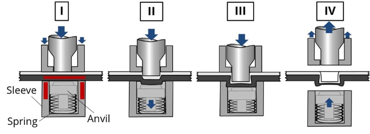
Fig. 1: Thermally supported clinching process with I) positioning, heating, fixation, II) drawing, III) extrusion, IV) removing finished joint
2.2 Numerical descriptions of joining processes
Previous simulation approaches for hybrid clinching joints use a macroscopic point of view. The FRTP is described as one homogeneous layer. This homogenisation for sFRT assumes an isotropic [6] or anisotropic material behaviour [4]. However, holeclinching leads to a lower deformation in the composite, so that an isotropic material behaviour based on stiffness determined with ± 45 °- tension tests [7] is assumed. In another mechanical joining process, the self-piercing-riveting-process, the FRP is described by a homogeneous anisotropic single layer stacking with cohesive zones between the layers [8]. This modelling approach enables a more precise description of damage, delamination and reorientation phenomena during the joining process. However, detailed information about the resultant material structure are not available. Another modelling approach on mesoscale for a novel hybrid thermoclinch joining process [9] is shown in [10]. The fabric was modelled in detail with each roving, which is assumed to follow an elasto-plastic material behaviour. In cause of the short flow paths of the heated matrix, the matrix was neglected. Additionally, coupling of the rovings and the matrix leads to instabilities and simulation abort [11]. In the numerical investigations for the TSC it could be shown, that axisymmetric models with a homogeneous material approach and only the simulation of the fabric is not sufficient.
3 Advanced modelling techniques
The objective of the presented modelling approach is the prediction of the resultant material structure on mesoscale. For this purpose investigations of the ALE remeshing approach, the SPH- approach and also the final CEL approach were used.
3.1 Model set-up
The set-up of the model is shown in Fig. 2. The tools like punch, blankholder and the split die are modelled as rigid bodies to reduce the computational effort. In the first step, the blank holder clamps the sheets with a defined force. The constant temperature field is predefined at the organosheet. In the second step, the punch move with defined displacement downwards. The anvil has an initial positon of 1 mm above the sleeve and an ending position at 1mm under the sleeve (see Fig. 2). The movement of the anvil is controlled by a spring with a defined stiffness and the two stops. The metal sheet is positioned punch-sided and the organosheet is positioned die-sided. In order to predict the material structure, fabric and the matrix material domains are modelled separately. The fabric is created with geometry data based on micrographs and modelled using a Lagrangian mesh with 2 elements over the thickness [1]. The matrix is simplified as a cuboid. The fabric is embedded into the matrix domain and the coupling depends on the presented modelling approaches.
For the thermoplastic PA6, a temperature-dependent isotropic elastic-plastic material model is implemented. The temperaturedependent yield functions are based on tension tests of unidirectional specimens in 90°-direction up to 160 °C [12]. The engineering constant for 180 °C is extrapolated. The GF-rovings of the fabric are described with a transverse isotropic elastic material behaviour. The engineering constants are also based on tension and shear tests up to 160 °C and were extrapolated for 180 °C [12]. Additionally, a material failure criterion for fibre tension rupture is implemented, leading to element erosion after reaching a defined elongation strain. This avoids excessive element distortions, which are mainly caused by the resultant ductility of the matrix due to high temperatures and its subsequent low fibre support. Tensile fibre failure as a result of punch movement induced fibre elongation is dominating the failure behaviour. The used metal sheet material DC05 is described by the Johnson-Cook-model. The parameters for this model are calibrated by tension test at different strain rates. Because of a constant temperature at approx. 200 °C, the temperature-dependent behaviour is neglected.
The contact definition is based on the penalty-formulation. The contact between the tools, the rovings and the matrix is defined with a hard normal contact behaviour and a friction coefficient of 0.3 in tangential direction. The contact definition between the rovings themselves is described by a pressure-overclosure-definition according to [2]. This definition takes the compaction of the rovings during the joining process into account. Furthermore the general contact definition in ABAQUS allows the definition of self contact, which is necessary to detect new contact surfaces caused by element deletion.
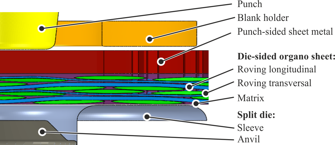
Fig. 2: model set-up for Hotclinch-process
3.2 Arbitrary Lagrangian-Eulerian – ALE
The ALE adaptive meshing method is an often used method for adaptive mesh smoothing to avoid element distortion. The deformation is therefore calculated by the classical Lagrangian method and the elements nodes are displaced. Afterwards, only the displaced nodes will translate in a manner that the resultant element mesh has no distortion (corrected elements). The strain and stress values of the deformed elements will be weighted and transferred to the corrected elements. In ABAQUS the limitation of this method is the combination with contact formulations: The nodes of the body surfaces, which are included in a contact formulation, cannot be moved to avoid element distortion [13]. This implies for the rovings, which are described by 2 elements over the thickness, that cannot prevent element distortion. Hence, the adaptive meshing will just be applied to the metal sheet. The modelling of the “soft” matrix during the radial displacement with the related large deformation in the bottom area and the necessary contact definitions leads to strongly distorted elements and to simulation aborts. The resultant material structure with this modelling approach at 160 °C is shown in Fig. 3. It can clearly be seen that the undercut could not be predicted because the compaction in the
neck area is too high. This stands in good agreement with 2D results of [1]. But the simulation shows a very sensible behaviour to the stacking position of the fabric. Especially a stacking of crimp zones leads to an unsymmetric joining zone and material structure.
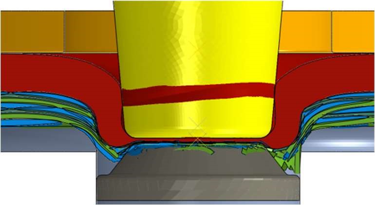
Fig. 3: Results of the clinching process with the ALE-approach for metal sheet and fabric without matrix
3.3 Meshfree methods
Another approach to manage large deformations and to avoid excessive element distortion is the use of meshless methods like the smooth particle hydrodynamic method (SPH-method). The SPH-particle, which is defined as a point mass, follows the description of Lagrangian formulation with these meshless elements. The link between these particles is generated by a defined interaction radius. All particles inside of this radius will interact. Thus it is possible to consider the material stiffness and to transfer forces, deformations and also stresses [13]. The Lagrangian formulation has a big advantage with regard to the formulation of contacts and coupling to other Lagrangian, non-SPH elements (e.g. hexader). Therefore, with this method it is possible to combine ALE-meshes with SPH.
Here, the metal sheet is defined as an ALE mesh to use the remeshing method. The matrix of the organosheet is defined as a Lagrangian mesh based on hexaeder elements around the joining zone. In the middle of the joining zone the matrix is represented by the SPH approach (see Fig. 4). In this area large deformation are expected. The rovings of the fabric are also modelled with Lagrangian elements. The results at 160 °C can be seen in Fig. 4. Due to instabilities of the contacts the simulation cannot be continued until the end of the process. It can be seen that the definition as point masses leads to unrealistic deformation at the metal sheet (Fig. 5). This is caused by the mass concentration and the mass scaling to reduce computational time.
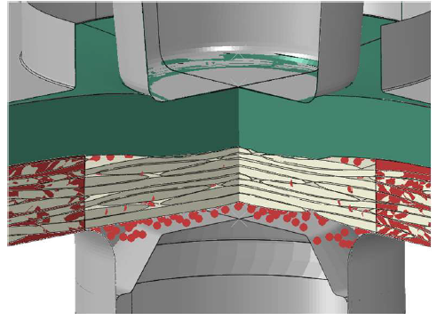
Fig. 4: Deformed model during calculation with the SPH-approach
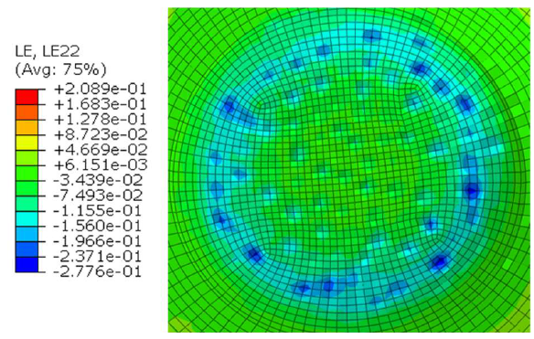
Fig. 5: Strain peaks in thickness direction of metal sheet at the approach bottom area as a reason of the mass concentration of the particles
3.4 Coupled Eulerian-Lagrangian – CEL
The final model is based on the CEL method for the metal sheet and matrix. This approach uses a stationary Eulerian mesh where the material moves through the mesh. Due to the stationary mesh distortions are avoided. The surfaces of each material is detected automatically and can interact with Lagrangian meshes. Preliminary investigations of this approach, using the metal sheet and the matrix without the rovings only, show that it is capable to fully describe the matrix displacements in the bottom area (Fig. 6).

Fig. 6: resultant joining zone with CEL- approach neglecting the rovings
The approach is capable to compute the occurring large deformations. However, it comes with the drawbacks of being computationally expensive and that mass scaling for the Eulerian domain cannot be defined in ABAQUS. The final model considers a process temperature of 180 °C in the area of the joining zone. The anvil is initially set to the end position. In order to perform the simulation in a certain time, the process time is scaled down to 1*10-3 s and the mass scaling for the rovings with the Lagrangian mesh is set to 1*10-8 s. Moreover the interaction between the rovings and the matrix is not taken into account due to stability issues. The results are presented in Fig. 7.
It becomes obvious, that the material structure in the bottom area and in the ring channel is in good agreement with the micrographs. In contrast, the neck area and the undercut do not correlate to the experimental results. During the simulation, the rovings move upwards as a consequence of the impact of the punch and the mass scaling. Therefore, the rovings are compacted at the lower side of the metal sheet. This leads to an incorrect prediction of the neck area, which is in contrast to the simplified model at 160 °C in Fig. 6. This discrepancy of the full model can be explained by lack of volume. This lack is justified by the inaccuracy of contact formulation in the bottom area for the matrix. Therefore, the required pressure to form the undercut cannot be achieved. However, the radial displacement of the matrix up to a thickness of 0 mm and fibre failure in the bottom area can be modelled very well with this approach. The comparison of the punch force and the punch displacement is given in Fig. 8. The maximum of the punch force and the predicted stiffness in the last step of the joining process are in good agreement. In this stage of the process, the punch reaches the end position and the metal is deformed correctly.
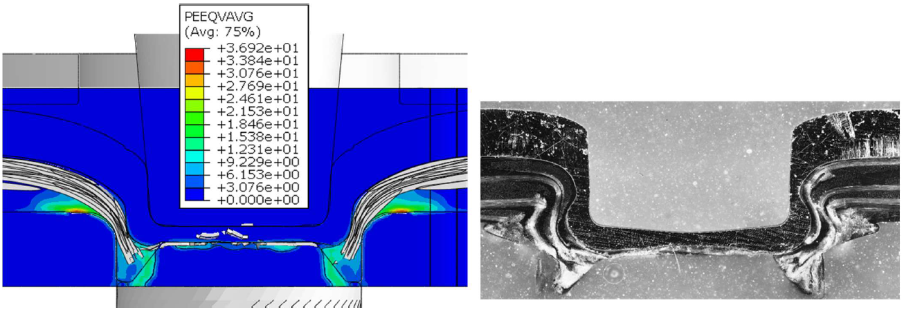
Fig. 7: Comparison of the resultant material structure in the CEL- model (left) and a micrograph (right)
In conclusion, the CEL approach is capable to simulate major effects of the joining process but there is a lack of information about the interaction between the fibres and the matrix and the friction between the rovings.
4 Results and Conclusion
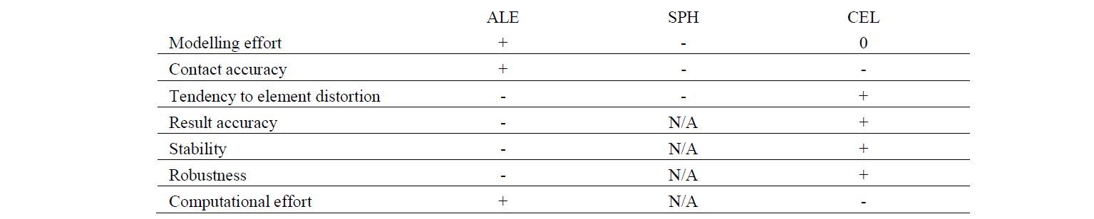
Approaches for the numerical description of the TSC joining process to predict the undercut, the resultant material structure and to evaluate the load bearing behaviour are presented. ALE, SPH and CEL-approaches are compared and evaluated in terms of robustness and stability of the joining process simulation (Table 1). In general, all approaches revealed major problems regarding the contact formulations and the interaction of the joining partners. Especially the interaction of the heterogeneous composite with the ductile matrix and the rovings as well as the occurring the large deformation leads to instabilities and caused aborts in the simulations. The conclusion of the numerical investigation for the numerical description of the TSC shows that CEL- approach can predict the material structure of the composite and an undercut of the clinching point.
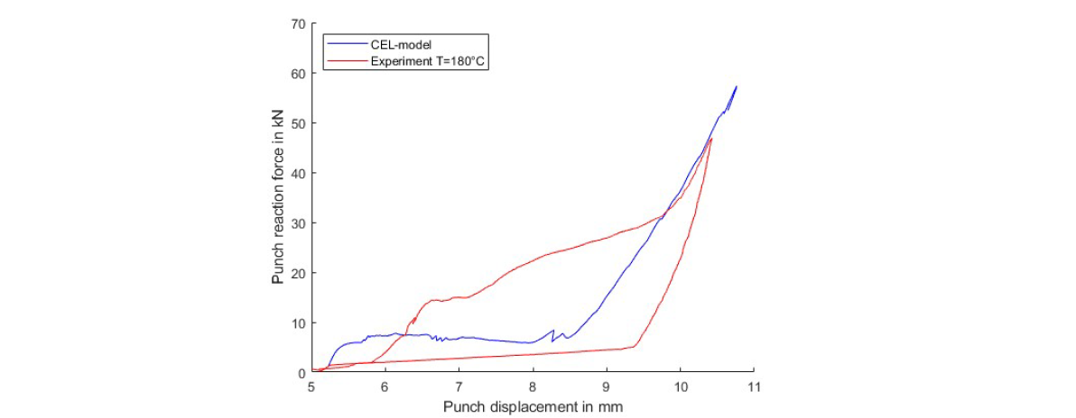
Fig. 8: Punch force and punch displacement for the simulation (blue) and the experiment (red) of the joining process
The Lagrangian based approaches are leading to instabilities in the simulation and phenomena, which are solely caused by the numerical method itself (mass concentration at SPH, distorted elements at ALE). Also, they generate a lack of volume inside the die due to element erosion. Due to the radial displacement of the matrix in the joining process, the simulation approach should handle these type of deformation phenomena. The CEL-approach is very time consuming and requires high standards in terms of computational hardware. The discrepancies in terms of fibre deformation and the undercut are caused by the unknown friction behaviour. Additionally, a lack of interaction possibilities between the CEL-domain (matrix) and the Lagrangian domain (rovings) and the material stiffness of the matrix at process temperature causes deviations. Additionally, the simplified heat area and the neglected cooling process during the process may lead to the deviations in comparison with the micrographs.
Table 1: Comparison of the different modelling approaches
Acknowledgements
This research was funded by the Deutsche Forschungsgemeinschaft (DFG, German Research Foundation) – TRR 285 – Project-ID 418701707, sub-project A03.
