1 Introduction
As a result of the ongoing global digital transformation and the associated digitization of manufacturing chains, traditional manufacturing industries are facing an increasing shortage of skilled workforce. This is due to the fact that the digital change requires not only indispensable technical knowledge but also expertise in use of corresponding software tools. Particularly in the process planning of automotive sheet metal forming parts for outer skin body panels, an increased gap between the engineering and the shop floor level is becoming apparent in this respect. Main objective during die manufacturing phase is the realization of most realistic contact areas. The implementation of simulated die surfaces in die manufacturing and the required spotting is a cost-intensive and time-consuming task caused by empirical assumptions during the manufacturing process.
Die tryout closes the mentioned gap resulting in a reliable die performance and therefore in enhanced part quality. The part quality is significantly determined by a variety of influencing parameters and their consideration in the sheet metal forming simulation. Recent research in the field of process simulation in sheet metal forming is therefore concerned, among others, with the modeling of materials [1], the representation of friction conditions by increasingly complex modeling approaches and the investigation [2–4], prediction and compensation of flange spring back [5,6]. However, all this work does ignore the fact that all the issues covered may have their origin in the definition of contact condition between the die and the blank.
In today´s sheet metal forming simulations, the tribological system that significantly influences the forming process is frequently only considered from the perspective of friction. Main system boundaries in the tribological system are specified by contact areas, which are in most cases only considered by an idealized numerical factor. Such a numerical factor generally describes a homogenous contact surface and pressure distribution for the entire drawing depth. This ideally calculated distribution is subsequently used as an objective to characterize physical die spotting, degree of spotting quality and is evaluated qualitatively by a homogeneous pressure distribution spotting image. Physically, however, this objective cannot be achieved as the sheet metal is subjected to thickening and thinning, affecting tremendously contact areas during the drawing process.
In sheet metal forming simulation, all components interacting with the blank are generally considered as rigid shells [7–9]. Therefore, modeling the contact conditions between tool components and blank utilizing a numerical factor. AutoForm describes this numerical factor as tool stiffness. Default values for this tool stiffness are based on finished spotted tools, having low values representing homogeneous contact areas and high values taking straining effects into account as well. Usually, a range from 10 MPa/mm to 100 MPa/mm is used for process planning with AutoForm R8 [7]. In literature, however, applications can be found using values of 1000 MPa/mm [10] and values greater than 10,000 MPa/mm [11] for the tool stiffness. Thereby, these higher values show an improved prediction accuracy with respect to measured validation data. Nevertheless, in current research, there is no specified numerical factor to characterize stiffness in perpendicular direction onto contact areas that can be related to real part projects.
For this reason, this paper presents an approach that allows an estimation of such numerical factor based on measured forming results. By using an experimental validation setup, part results are transferred back into the simulation, thus enabling a systematic analysis of the numerical contact factor for a downstream contact design improvement. The validation workflow for the contact factor described in this paper allows a procedure for the definition of component-specific numerical simulation parameters, which allows for an improved representation of contact areas during sheet metal forming simulation. Ath the end, this specified workflow leads to a modified die face design in process planning, enabling material-efficient die design and shortened die tryout time periods.
2 Numerical background of the tool stiffness factor
Die surfaces of, for example, punches, upper dies and blank holders are generally considered as rigid objects in sheet metal forming simulation. Therefore, it is not possible to model the elastic behavior and the resulting locally variable pressure distributions of such components without additional contact conditions. This insufficient application of the numerical contact description is solved by the numerical parameter of the tool stiffness in AutoForm. Thereby, the current sheet thickness distribution in the part flange is determined at each time step of the forming simulation and contact conditions are modified accordingly. If the current local sheet thickness is greater than or equal to the initial sheet thickness, a numerical contact pressure is calculated. If the current sheet thickness is smaller than the initial sheet thickness, tool stiffness is used to adjust the contact condition. A schematic representation of this dependency can be seen in the following Fig. 1.

Fig. 1: Numerical modeling of contact distribution based on material thinning (blank thickness t < initial thickness t) and thickening (blank thickness t > initial thickness t) by a numerical tool stiffness factor (TS) in (a) default behavior and (b) variation of tool stiffness, e. g. AutoForm R8 [7]
If thinning of the flange material occurs within a time step, the solver numerically calculates a virtual adaption of the die surface, based on the selected value for the tool stiffness factor. As a result, the contact condition is adapted locally between blank and die surfaces and thus a locally applied pressure. The generated contact areas also affect the global blank holder pressure distribution due to the equilibrium of forces. Accordingly, a lower blank holder pressure is applied for thinner sheets. Different values of the tool stiffness can be used to adjust blank holder pressure distribution and thus to estimate the elastic behavior of the blank holder in the forming simulation.
3 Reversed engineering approach
The currently implemented default tool stiffness factor of 50 MPa/mm2 generally shows a homogenous pressure distribution which is not corresponding to real contact areas during deep drawing by physical material thinning [11]. It becomes apparent that a prediction of the real contact areas modeled with an adapted tool stiffness factor is suitable to enhance current forming simulation. Therefore, in the scope of this research, a workflow to determine this numerical factor is presented in Fig. 2.
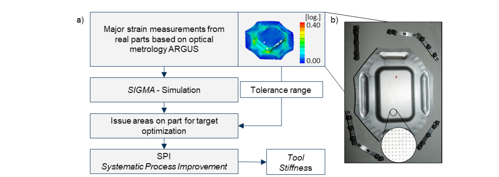
Fig. 2: Workflow for reversed calculation of tool stiffness values (a) based on validation data like major strain (b)
In the workflow shown in Fig. 2, a suitable tool stiffness is determined by corresponding real part data. This data is measured with optical forming limit analysis using GOM Argus [12]. An AutoForm sheet metal simulation based on a SIGMA simulation of the part, considering a varying tool stiffness, is used to perform a Systematic Process Improvement (SPI). The measured major strain for each validation part specifies the corresponding tolerance, which describes a target range for the improvement. Therefore, an adapted tool stiffness can be determined to obtain a blank holder pressure distribution, which corresponds to the material draw-in and the actual part quality.
In the following sections, a rectangular cup is used to evaluate the described workflow. Furthermore, the simulation results generated by the calculated tool stiffness factor are compared with the initial simulation model.
4 Forming data for validation
The experimental part used in the scope of the investigations is shown in Fig. 3. The part is related to a deep-drawing tool, which is operated on a single-acting press with a drawing cushion.
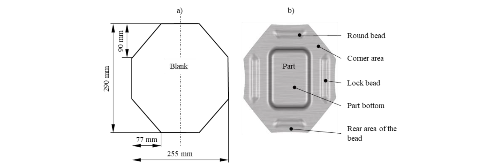
Fig. 3: Validation rectangle cup with blank dimensions (a) and bead geometries (b)
The cup is drawn using an octagonal blank made of one millimeter thick AL6-Out (aluminum) sheet material. Apart from controlling material flow by means of the blank holder force, different bead geometries previously were implemented. Lock and round beads enable a stretch bending influence during deep drawing for thinning and thickening areas. Corner areas are offset by -0.1 mm and the rear area of the bead by -0.2 mm, avoiding contact in these areas.
5 Improvement of tool stiffness
The SPI functionality in AutoForm R8 enables automated analysis of part qualities. Thus, specified failure criteria like splits or wrinkles, are checked and compared to tolerance specifications defined in the software. This SPI analysis can also be transferred to stochastic forming simulations, so-called SIGMA simulations. In this case, a corresponding parameter setting based on the meta-model leads to increased part quality or fulfills tolerance specifications for an operation point [7].
With regard to the calculation of an ideal tool stiffness of a specified forming process, the fulfillment of specifically defined tolerances in selected part areas is of particular interest rather than global part quality. These tolerance specifications are adjusted according to the measured part data. For example, it is possible to assign a corresponding specification or tolerance to either the blank holder pressure, the blank draw-in or the determined major strain based on the existing data set. Using the major strain enables a reliable measurement with the lowest deviation due to optical measuring technology. Nevertheless, recorded spotting images, contact patterns, and draw-in are usually used for validating the simulation results and thus the calculated tool stiffness. However, these measurement results are actually not suitable to be used for tolerance specification objectives due to their insufficient accuracy. Thus, the measurement of sheet metal draw-in is subjected to considerable measurement fluctuations and proves to be particularly difficult with curved parts.
With regard to the rectangular cup considered in this paper, the SPI-tolerances were specified using the measured major strain. The evaluation area analyzed hereby is called issue in AutoForm and usually represents a critical part area. However, in the workflow described in Fig. 2, this functionality is used for the intended improvement and is not necessarily associated with a part area exposed to extreme loads. When defining the part areas for calculating the tool stiffness the greatest possible variation of major strain should be selected precisely (see Fig. 4). This leads to an ensured variation of the tool stiffness to achieve the specified tolerance range.
For the presented validation part, the area in the die radius was selected according to the specifications defined in Fig. 4. Here, in the real part, a maximum deformation of φ1 = 0.111 was determined, whereas in the initial reference model the value of φ1 = 0.136 was calculated. This represents a significant deviation of +22.5 % and an overestimation of the major strain, as shown in Fig. 6. The tolerance specifications for systematic process improvement were selected as listed in the following:
-
Upper warning level: φ1 = 0.112
-
Lower warning level: φ1 = 0.110
Fulfillment of these tolerance specifications was achieved by a systematic process improvement based on the meta-model using a tool stiffness of 2500 MPa/mm. The corresponding calculation for the tolerance specification by the SPI is presented in the following Fig. 4. Here, the major strain in the selected die radius (DR) is continuously decreasing until the tolerance band is reached.
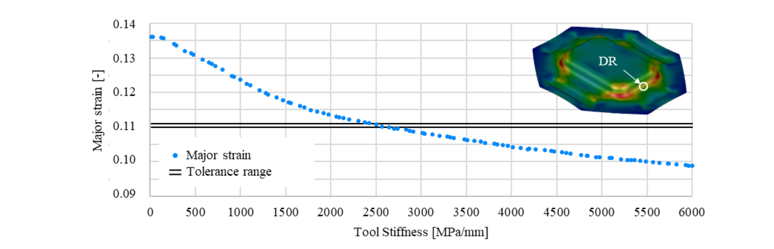
Fig. 4: Variation of the tool stiffness in the upper dies radius regarding the major strain at the die radius (DR) using SPI
6 Evaluation of the adjusted tool stiffness
By comparing the pressure distributions in the flange area of the validation part with those calculated with the initial simulation and the simulation using a tool stiffness of 2500 MPa/mm, the significant improvement of the prediction accuracy due to the adjusted tool stiffness becomes apparent. The corresponding pressure distributions are shown in Fig. 5. The forming simulation with adjusted tool stiffness shows a concentration of the blank holder pressure in the corner areas, as indicated by the Fuji Prescale foil [13].
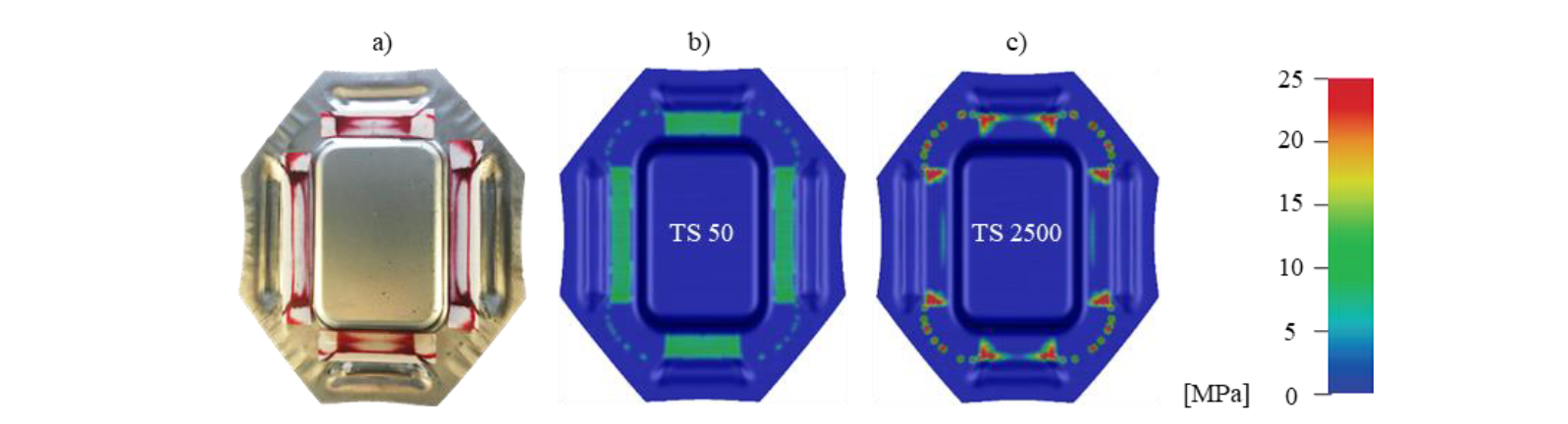
Fig. 5: Comparison of the blank holder pressure distributions in the operating point at default tool stiffness 50 MPa/mm (b) and tool stiffness of 2500 MPa/mm determined by SPI (c) with the real spotting images (a)
Comparing the major strain and the blank draw-in, an improved approximation of the simulation model towards the measured part data can be noted, as presented in Fig. 6. In particular, the major strain curves at the bottom of the part and the wall fit the measured data. This correlation is particularly noticeable due to the previous specification of the tolerance for the SPI. In addition to the improved major strain prediction, the comparison of the sheet draw-in additionally shows an approximation to the real part data.
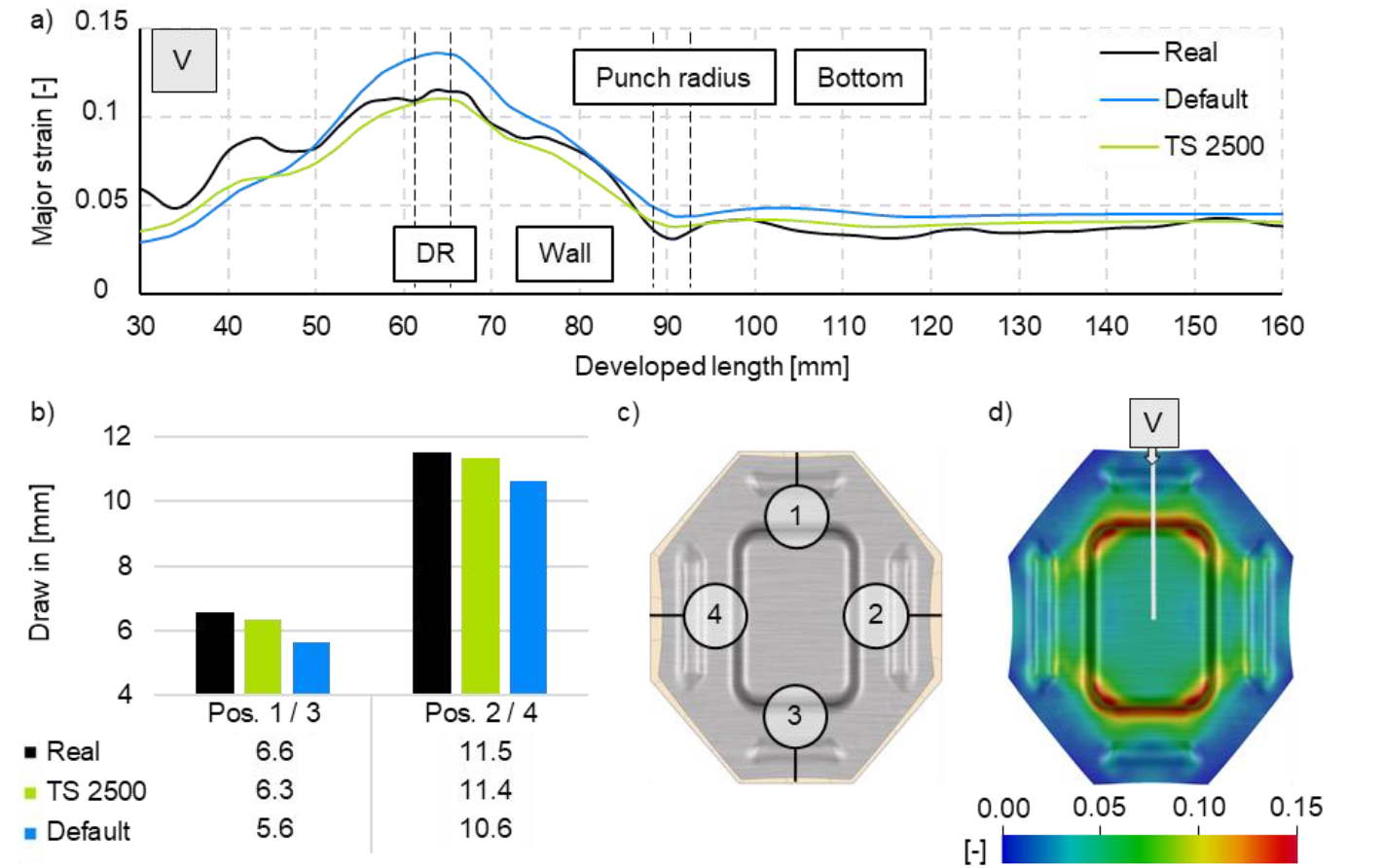
Fig. 6: Comparison of the major strain curves die radius (DR), wall, punch radius and bottom (a) at position (d) and draw-in (b) with real part data at four positions (c)
In summary, the resulting improvements in numerical major strain prediction were achieved by appropriate modelling of the pressure distribution using the numerical tool stiffness factor, thus allowing a reliable estimation of real contact conditions between blank and die in forming simulation. Consequently, it can be assumed that this improved prediction accuracy will enable more efficient die development and manufacturing processes in the future.
7 Conclusion
This paper shows how data feedback through reverse engineering enables an improved sheet metal forming simulation. Real major strain data were used as input for systematic process improvement. This allowed an adjustment of the contact conditions by a numerical factor during the deep drawing process. The numerical tool stiffness factor was improved in order to achieve realistic inhomogeneous contact conditions, due to the consideration of thickening and thinning effects. This enabled an improved prediction accuracy for the rectangular stretch-bended cup analyzed in this work. Especially, prediction accuracy of the major strain as well as the draw-in were improved.
Further research will focus on the validation and evaluation of the presented systematic improvement approach. In order to define appropriate component-specific parameters for the contact condition further sheet metal forming tools for body panels need to be analyzed by the workflow. This enables a database of numerical factors for similar part categories. The consideration of the changing contact areas leads to a modified contact area design in process planning. Furthermore, the numerical factor can be used as a final validation value for a reliable simulated part quality validation. Due to that, an improved process planning leads to a resource-efficient die tryout.
