1 Introduction
Efficient shoes should provide adequate foot protection, safety, and comfort during operative tasks. A safer shoe should assure good traction or slip resistance for any slippery conditions [1]. A slip starts when low friction occurs between the shoe and floor surface. The coefficient of friction (COF) is affected by several factors related to the shoe design, the flooring design, and the liquid contaminant between the surfaces in contact [2]. For this reason, the interface conditions between the shoe and ground surface need to be accurately investigated during kinematic and kinetic studies. Several forces are simultaneously active in the shoe kinetics. The ground reaction force (GRF), opposite to the applied force on the shoe, consists of one vertical component plus two horizontals components. The vertical component is investigated to detect the ground contact in gait analyses. The horizontal GRFs are defined as anterior-posterior and medio-lateral components according to movements along and perpendicular to the motion direction, respectively. COF measure is strictly dependent upon the normal force, shoe-floor angle, and the horizontal sliding speed, trying to mimic the biomechanical conditions found during walking (biofidelic tests) [3]. The force platforms are the preferred measurement devices to evaluate the effects of the combined GRF components. These platforms are mechanical friction-testing devices generally belonging to two groups: portable devices applying low normal forces proportional to human body mass using a simple specimen, and whole shoe testers using a normal specimen and applying conditions very close to real ones [4].
The research in this paper focuses on the evaluation of a shoe thread using a numerical-experimental approach. The material properties and related influence on the coefficient of friction are investigated. The research considers the material characterization, the experimental setup of measure the forces and friction, and finally, the achievement of a virtual testing environment.
2 Materials and Methods
The investigated material was an NBR (Acrylonitrile-butadiene rubber), ideal for soles for indoors and outdoors, slippery or uneven surfaces, especially where chemicals/oils are present, and environments with extreme temperatures. Some in-depth analyses were performed to acquire a better knowledge of material characteristics, using Differential Scanning Calorimetry (DSC) and Dynamic Mechanical Analysis (DMA). DSC tests were performed to determine the main thermal properties of the NBR material. The measurements were carried out on a DSC 250 (TA Instruments, New Castle, USA), equipped with a Silver Furnace and innovative sensor technology, to perform measurements between -120°C and 200°C. The main processing factors of the DSC analysis were the thermal cycle as well as the heating and cooling rates. The thermal cycle consisted of a single run with a heating step from -100°C to 200°C with a heating rate of 20°C/min, a holding step for 5 minutes, and a cooling step from 200°C to -100°C with a cooling rate of 20°C/min for samples weighing about 10 mg, according to a well-known procedure [5]. Figure 1 shows the resulting DSC thermographs of the heating and cooling phase. The glass transition Tg and the endothermic transformation Te temperatures were detected at -19°C and 103°C, respectively.
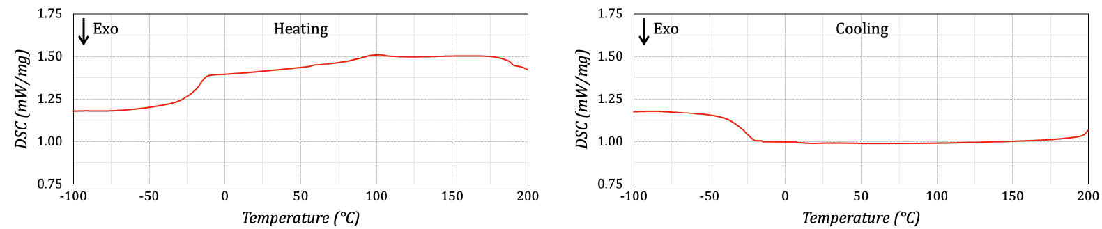
Figure 1. DSC thermograms of heating (left side) and cooling (right side).
DMA analyses were carried out using a DMA 850 (TA Instruments, New Castle, USA) to monitor the storage G’ and loss G” moduli of the NBR material, under oscillatory load, against time, temperature, and frequency of oscillation while a programmed thermal cycle was executed [6]. The use of DMA provided another method to measure the glass transition temperature Tg. The thermal cycle consisted of a single run with a heating step from -100°C to 200°C with a heating rate equal to 10°C/min, a frequency of 1 Hz, and a strain amplitude of 4 µm. Figure 2 shows the obtained DMA results in terms of G’, G”, and tan δ. The Tg value was identified from the maximum of tan δ as a function of the temperature, where tan δ is the loss factor. The Tg value was equal to 15°C, very near to the value identified with the DSC analysis. The storage modulus values of the examined NBR material decreased with an increase in temperature. In the temperature range from – 50°C to 0°C, the main loss of storage modulus, by more than two decades, was observed due to Tg presence. After the transition to the rubbery elastic region, the storage modulus values of the examined NBR did not change significantly in the measured temperature range.
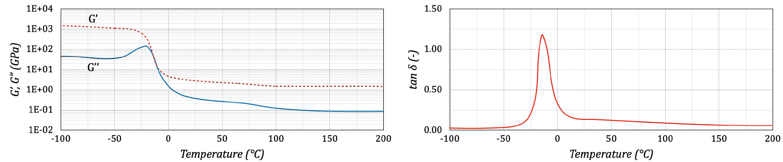
Figure 2. DMA thermograms of G’, G” (left side), and tan δ (right side).
The results of DSC and DMA analyses, together with those of tensile tests, are summarized in Table 1.
Table 1. Material data - NBR.
|
Properties |
Value |
unit |
|
Physical Density |
1.21 |
g/cm3 |
|
Glass Transition Temperature Tg (DSC) |
-19 |
°C |
|
Glass Transition Temperature Tg (DMA) |
-15 |
°C |
|
Endothermic Transformation Temperature Te (DSC) |
103 |
°C |
|
0.5% Weight Loss Temperature TZero (TGA) |
135 |
°C |
|
Enthalpy of Transformation ΔHe (DSC) |
40 |
J/g |
|
Mechanical Young’s Modulus |
0.2 |
GPa |
|
Yield Tensile Strength |
25 |
MPa |
|
Ultimate Tensile Strength |
38 |
MPa |
|
Elongation at break |
320 |
% |
|
Coefficient of Thermal Expansion |
154 |
µm/m/°C |
The properties of NBR are very strictly influenced by the ratio of acrylonitrile groups to butadiene groups in the polymer backbone, defined as the Acrylonitrile (ACN) content. The lower the ACN content, the lower the glass transition temperature. On the contrary, the higher the ACN content, the better resistance the polymer has to nonpolar solvents. For his reason, the value of the Tg pointed out that the selected NBR had good solvent resistance and low-temperature flexibility. These results pointed out the high quality of the NBR material used for producing specimens and soles for the following experimental tests.
3 Experimental tests
The experimental tests were performed using a slip resistance testing machine STM 603 (SATRA Technology Europe Ltd, Kettering, UK). The machine was modified to mount a special rapid prototype device (Figure 3), which allowed circular inserts to be tested in substitution to the entire shoe (Figure 4). One advantage of this special device was the possibility of testing two inserts at a time with the same or different tread design. In addition, the circular shape of the insert also allowed the rotation around the vertical axis to evaluate the influence of this rotation of tread adhesion. The insert presented parallel grooves directed along the length of the shoe and perpendicular grooves directed at 90 degrees to the length of the shoe. The insert diameter was 100 mm.

Figure 3. Insert holder.

Figure 4. Testing configuration.
Friction tests were carried out in accordance with the EN ISO 13287 and ASTM F2913 guidelines. The parameters of the kinetic tests were a normal force of 0.5 KN, sliding velocity of 300 mm/s, and zero contact angle between the shoe and floor. All tests were performed on a ceramic tile floor with natrium lauryl sulfate (NaLS) 0.5 weight% in water. The contact area and hardness of each specimen were acquired before the test. The average hardness value was 62 Shore A. The contact area was measured by roll inking the tread surface and reporting the imprint on paper after positioning the specimen on the gait system. A digital image of the imprint was acquired by scanning and computing the contact area covered by black pixels. The ink was removed from the surface, and the contaminant was applied to the floor to guarantee a uniform film thickness without a barrier around the sliding region. After this preliminary phase, the test started. The normal force was linearly increased from 0 to 500 N into 150 ms. This interval was sufficient to attain the average ratio of shear to normal force after the full load was reached [7]. After this time, the thread moved for a total time of 500 ms. The GRFs were recorded from digital force sensors of the gait system for the entire time interval. Five measurements were done on each test, arriving at the stationary conditions and averaging the COF results for statistical analysis [8]. The interpretation of COF was the following. A low COF value was associated with low friction, suggesting that the floor provided less traction, and it was more slippery. On the contrary, a high COF was associated with more friction, denoting that floor provided greater traction, and it was less slippery. The floor surface was rinsed thoroughly and dried to remove all contaminant traces before proceeding to a new test. Figure 5 shows the acquired results in terms of normal force FN and frictional force FT and COF.
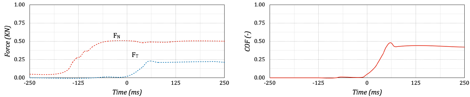
Figure 5. Acquisitions of forces (left side) and COF (right side).
4 Numerical model
A multiphysics finite element (FE) model was implemented to predict the GRFs and COF, stresses, and deformations during the friction test using COMSOL Multiphysics (Comsol Inc., Burlington, USA). Mechanical analyses were carried out at the mesoscale level by using a segregated solver splitting the Jacobian matrix into smaller sub-problems, usually one for each degree of freedom [9]. The segregated approach treated each physics sequentially, using the results of the previously solved physics to evaluate the loads and material properties for the next physics being solved. The advantages of this approach are several such as the use of an optimal iterative solver in each linear sub-step, a more memory-efficient faster solver and, less time for solving iterations than a fully coupled approach. The temperature fields were initially computed during the thermal analysis and then recomputed during the mechanical one to evaluate the induced strain and stress fields at each simulation step.
The FE mesh consisted of more than 350,000 mixed elements (prisms and quadratic hexahedrons) with a constant element length of 500 μm and an average mesh quality of 0.94. A high number of small-sized elements were used for the contact pairs between the specimen and ground, whereas large-sized elements were employed for areas out of the contact. The main assumptions of the model were: a) a linear elastic constitutive model was chosen for the description for both materials, considering ceramic (E = 440 GPa, ν = 0.3) and NBR (E = 0.2 GPa, ν = 0.3), b) a constant friction coefficient was assumed, c) symmetry and homogeneous contacts were considered on a flat interface, d) penalty method was selected to discipline the violation of the contact constraints, e) no external loads except normal force was applied to the mechanical model, e) the mechanical boundary conditions constrained movements along X, Y, and Z axes of the ceramic plate's bottom region.
The main processing parameters of the FE model were associated with the normal force and speed, selecting the same values of the experimental tests. The time step was small enough to accurately represent the movement without excessively increasing the solution time for contact and force computation. Figure 6 shows the contact between thread and floor, assuming values 0 and 1 for absence or full contact, respectively. Figure 7 shows the stress fields computed with travel speeds equal to 300 mm/s, using two different time steps. The first-time step (called Normal Force Applied) reported stresses at the application of the normal forces, whereas the second-time step (called After Displacement) showed stresses after the specimen moved for 500 ms.

Figure 6. Simulation results - Contact field.

Figure 7. Simulation results – Stress field.
Figures 8 and 9 show the comparison between forces acquired during the experimental test (dotted curves) and simulation computation (continuous curves), and the associated COF. A good agreement was achieved between experiments and simulation, confirming that the numerical model could be successfully used to predict GRFs and COF.
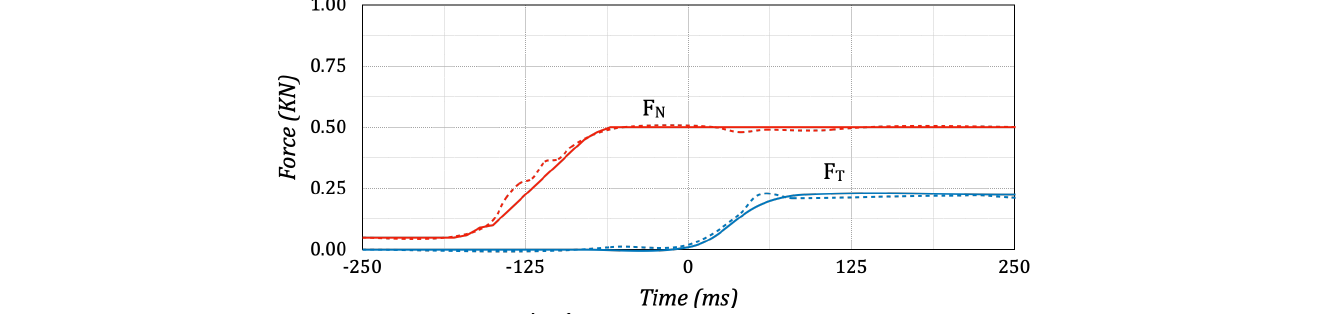
Figure 8. Simulation results – Force comparison.
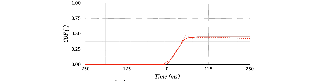
Figure 9. Simulation results – COF comparison.
Using this FE model, new configurations, as well as new thread designs could be virtually tested, reducing the experimental efforts.
5 Conclusions
The authors have investigated the interaction between an NBR shoe thread and floor using a single contaminant. The NBR material was characterized using DSC and DMA to identify main thermal and mechanical properties, evaluating the material characteristics in terms of good solvent resistance and low-temperature flexibility. These properties were used as the main input of the material data of the numerical model. The following experimental tests have allowed the acquisition for the normal and frictional forces, thus the computing of the relative COF to compare with the numerical prediction. Only once experimental configuration with a specific tread design has been used to assess the efficiency of the numerical model in respect of the experimental computations. The good agreement between experimental and numerical results allowed us to employ the multiphysics model as a virtual testing environment.
In future work, the experimental activities and the numerical model will be expanded to compute new testing configurations (different shoe-floor angles and contaminants), new process parameters (normal force and speed values), and innovative thread design. In addition, the virtual testing environment could be expanded to test the whole shoe instead of a single thread.
Acknowledgments
The authors wish to acknowledge and thank Raffaella Amoruso (Base Protection Srl) and Nicola Magaletti for their precious support during the research activities. The research was funded by Apulia Region in the framework Programmi Integrati di Agevolazioni (project ID MX7SBY6).
