1 Introduction
Stretch bending is widely used in the fabrication of lightweight profile products in many industrial sectors such as automobile, aerospace, shipbuilding, etc., owing to its high shape accuracy and process capabilities [1,2]. However, with the current transformation to the Industry 4.0 era, the manufacturing industry is rapidly changing towards higher flexibility to meet the increased demand for product diversification [3]. This brings a challenge to conventional stretch bending processes with low flexibility, and further calls for the development of novel stretch bending technologies for high flexibility and geometrical complexity of products, as well as low tooling investments, thus seeking for improved competitiveness in a dynamic market.
As a countermeasure, some attempts have been made to enhance the flexibility in stretch bending of profiles. Recently, a new concept—flexible rotary stretch bending—was introduced for forming complex shapes including both two-dimensional (2D) and three-dimensional (3D) profile parts [1,4]. In this strategy, the increased flexibility is realized by adding rotational axes combined with a flexible tooling concept utilizing part-specific inserts to enable the manufacture of more complex part configurations with low tool costs. However, as the process is new, relatively less fundamental knowledge is established, which makes it difficult to efficiently design, analyze and control this flexible forming process.
Real-time forming force is one of the most fundamental aspects concerned with a forming operation. In-depth knowledge of forming forces during loading cycles not only contributes to the improvement of product quality and preservation of machine/tooling system, but is also of particular importance to adaptively control the process, Moreover, variability in forming force characteristics are essential to variations in springback as well as optimization of energy consumption. Therefore, effective modeling of forming forces can greatly benefit product design and process control. For instance, knowing real-time forces can solve the internal moment applied in the formed profile, which can be further used to establish an intelligent system for controlling springback [5,6]. It is known that empirical, numerical, and analytical methods are widely employed to modeling the forming forces, among which the analytical methods can offer a rapid assessment of forces and the effects of influential parameters can be qualitatively estimated, thus providing an effective means to make the force knowledge more explicit and reuseable. At present, extensive analytical models have been developed to analyze force requirements in many processes like incremental sheet forming [7], incremental profile forming [8], and stretch bending of profile [6, 9]. However, for the flexible rotary stretch bending processes described above, there is still a lack of analytical models applicable for instant force prediction. Especially, for the modeling of real-time forces throughout the forming process, few relevant studies are found.
In this paper, we present a strategy for efficient analytical prediction of real-time forming forces in flexible rotary stretch bending process, aiming to provide an effective means to know and to understand the force knowledge for improved process control. First, an overview of the new flexible rotary stretch bending process for forming complex shapes is given. Then, from the point of kinematic analysis of forming process, an analytical model is developed to predict selected real-time forming force components of the machine system. Finally, based on finite element (FE) simulation, the accuracy of the analytical model is validated in the forming of rectangular hollow, aluminium alloy profiles for applying different pre-stretching levels.
2 Flexible Rotary Stretch Bending Process
To meet the demands for complex product geometries, a new stretch bending process is developed to enhance flexibility based on the 3D bending theory reported in reference [1]. Fig. 1 (a) presents a schematic view of the forming method and machine design, in which the innovative strategy is based on adding multiple rotational and (or) translation axes combined with a flexible design of dies with different geometrical configurations, thus allowing the manufacture of complex-shape profile products.
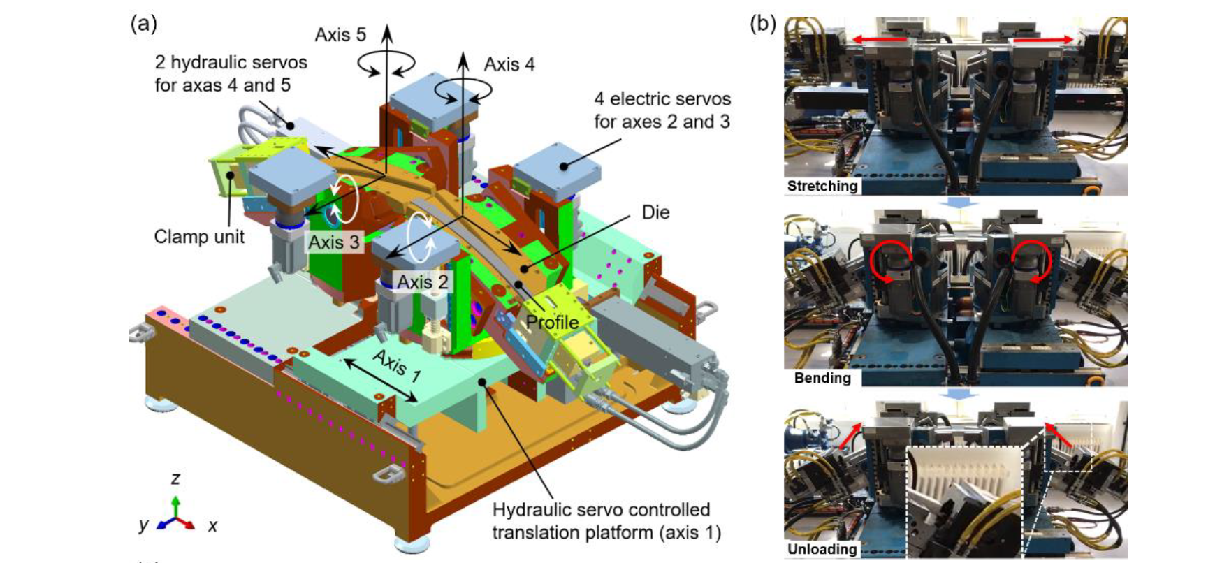
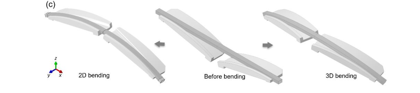
Fig. 1 Novel 3D, flexible rotary stretch bending method: (a) overview of the forming method and machine design [1]; (b) the built machine and the stretch-bending-unloading process; (c) schematic view of 2D and 3D bent parts.
It can be seen from Fig. 1 (a) that this machine system consists of two opposing sets of bending arms. Each bending arm provides three degrees of freedom (DOF), including (1) one rotational DOF in the vertical x-z plane controlled by Axis 2 and Axis 3, which enables bending in the vertical x-z plane; (2) one rotational DOF in the horizontal x-y plane controlled by Axis 4 and Axis 5, which enables bending in the horizontal x-y plane; and (3) one translational DOF in the base structure (x-direction) controlled by Axis 1. In the forming process, if only Axis 2 and Axis 3 are activated, two-dimensional (2D) bending can be realized. When Axes 2~5 are simultaneously activated, complex 3D bending can be realized. The translational movement can provide the bending process with pre-/post-stretching or in-process (simultaneous) stretching, thus optimizing the forming process for minimum springback and improved forming quality. For the design of the machine system, Axis 2 and Axis 3 use electric servos and rotary absolute encoders; Axis 4 and Axis 5 are controlled by hydraulic servo actuators and linear absolute encoders; Axis 1 is realized by the movement of the hydraulic servos controlled base platforms relative to each other. Based on the above-described design method, a full-scale machine is built and installed in NTNU Aluminium Product Innovation Center (NAPIC), as shown in Fig. 1 (b). The newly-established machine system can fabricate both 2D and 3D bent configurations, as shown in Fig. 1 (c). Overall, compared to the conventional stretch bending processes, this flexible rotary stretch bending method allows the fabrication of different geometrical configurations with the use of only one set of tools, thus improving the flexibility and reducing the tooling investment. Moreover, the multiple rotational/translational axes can make the forming process more controllable, thus improving the dimensional accuracy of formed products. In this study, we limit the focus to analytically modeling the real-time forming forces in a 2D bending configuration only.
3 Analytical Modeling of Real-Time Forming Force
In the rotary stretch bending process, the geometrical configuration includes both bent and straight portions, as shown in Fig. 2 (d). Due to symmetry, the half CAD model will be used for analysis in the following. As described above, the stretching can be applied in different modes; i.e., before, during, and after bending. In this work, we mainly focus on forming with pre-stretching applied (stretching before bending). Fig. 2 (a) ~ (d) illustrates the different stages during the entire forming process from the initial state to the finally formed part.
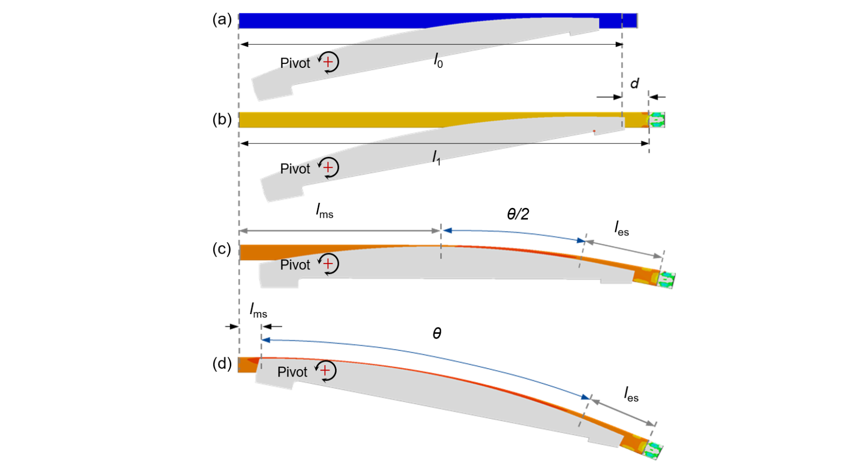
Fig. 2. Forming process of rotary stretch bending of profile: (a) before forming; (b) pre-stretching; (c) during bending; (d) after forming.
To calculate the real-time forming forces, the strain distribution of the profile during the entire process must be determined analytically. As the longitudinal strain component dominates deformation upon stretching and bending, it is taken to represent the total strain. In the pre-stretching stage, the nominal longitudinal strain (𝜀s) with respect to stretching displacement (𝑑(𝑡)) can be written as:

where l0 is the initial length of the profile before forming, and t is the loading time, and the total loading time of pre-stretching is denoted as t1.
During the combined stretch-bending operation (in short described as ‘bending stage’), however, the geometric locations of the pivots (as shown in Fig. 2) will induce a stretching strain 𝜀sb, even without the initial pre-stretching applied; that is, the total stretch strain is composed of the additional strain induced by pre-stretching and the strain induced by the rotational movement, depending on the locations of pivots, creating combined stretch-bending. This stretching strain component (𝜀sb) created during the bending stage is considered to be proportional to the bending angle and can be given by:

where ε0sb is the total accumulated strain created by the combined stretch-bending process without the pre-stretching strain, when the profile is formed to the final bending angle (θ0), θ(𝑡) is the real-time bending angle during the forming process, t2 is the total cycle time, and thus (t2−t1) is the loading time of the bending stage. According to the geometrical relations shown in Fig. 2, ε0sb can be calculated as ε0sb=((lms+Rcθ0+les)−l1)/l1, where l1 is the horizontal distance between the symmetry plane and the end of profile before bending operation, and Rc is the bending radius of the neutral layer of profile. Based on the principle of superposition, the total stretching strain εb(t) in the bending stage is a sum of the pre-stretching strain εpres(t1) and the real-time bending strain εsb(t), which can be expressed by:

Thus, the strain during the entire forming process can be described as:

Here Hooke’s law and a Ludwik-type equation calibrated by the engineering stress-strain curve are used to model the elastic-plastic response of the profile, as given in the following:

where E is Young’s modulus, σ0 is the yield strength, n is the hardening parameter, and ε0 is the offset coefficient. Thus, by combining Eqs. (4) and (5), the axial force N(t) of the formed profile can be solved as follows:

where A is the nominal sectional area of the profile. For a rectangular hollow profile with a uniform thickness, the sectional area can be calculated as A=wh−(w−2t).(h−2t), where w, h and t are the nominal width, height and thickness of the profile, respectively.
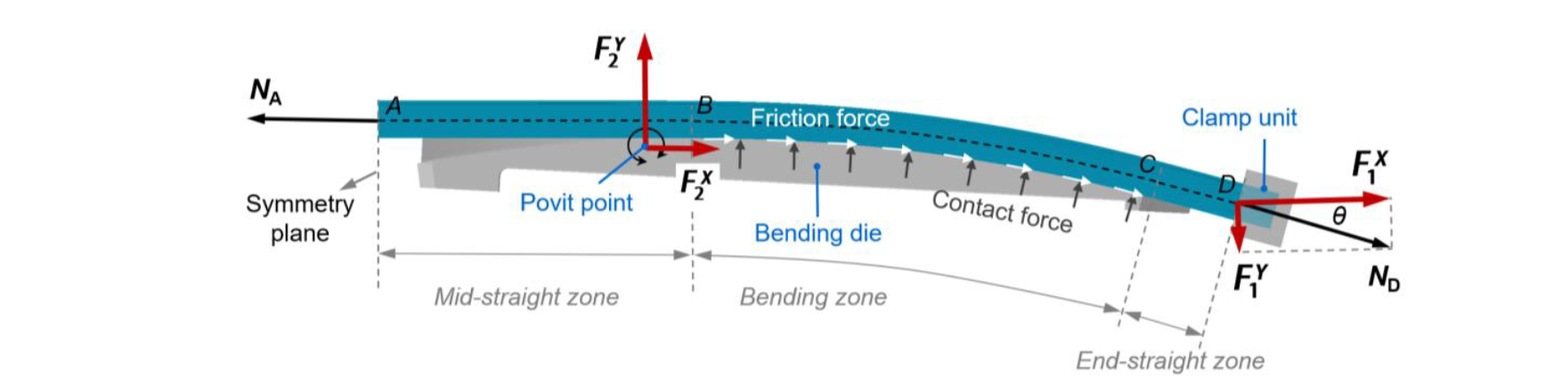
Fig. 3. Force analysis of stretch bending process.
For a more accurate analysis of forming force, friction between tool and workpiece needs to be modeled. Fig. 3 shows the static analysis model of forces during the forming process. Here it is assumed that the friction only exists in the bent portion (BC) and the Coulomb friction law with a coefficient μ is used. For the straight portions (AB and CD), zero friction is assumed and thus the axial forces at different reference sections follow NA= NB, and NC= ND. Then, solving the equilibrium equation at the arbitrary sectional position 𝛼 can lead to a well-known capstan-type model [9], and thus the axial force (Nα) at section-α can be obtained:

Due to the friction effect, the axial force in the bending zone is non-uniform. Thus, the axial force at the mid-section (α= θ/2) is used as a reference to inversely calculate the distribution of axial force in the entire bending zone. This reference value is assumed to be equal to N(t) that is calculated in Eq. (6). As a result, by combining Eq. (6) and (7), the axial force at section-A (symmetry plane) can be solved as NA=N(t) exp(μθ/2), and thus the axial force distribution Eq. (7) can be re-written as follows:

Based on the equilibrium analysis in the global forming system (as shown in Fig. 3), neglecting the shear force across the sections of the formed profile, the following equations can be obtained:

where Nαμ and Pα denotes the friction force and contact force between bending die and profile at section-α, respectively.
During the rotary stretch bending process, both the clamp unit and bending die are applying forces to the profile. As shown in Fig. 3, F1X and F1Y are the forces applied by the clamp unit in horizontal and vertical directions, respectively, and F2X and F2Y are the forces applied by the bending die in the two directions, respectively. For the clamp unit, the recorded forces F1X and F1Y and from the machine system can be described as:

For the bending die, the recorded forces F2X and F2Y and from the machine system can be obtained from an equilibrium analysis in the global system, and calculated as follows:

Consequently, by introducing the control functions of loading velocities, i.e. d=d(t) for pre-stretching and θ=θ(t) for bending subprocesses, the real-time forces throughout the entire forming process can be solved as follows:
-
Clamp unit:

-
Bending die:

4 Model Assessment and Discussion
AA6082-T4 extruded rectangular, hollow profiles are used as the case material for the assessment of the analytical model. The width of the profile is 60 mm, the depth is 40 mm, the gauge thickness is 3 mm, and the outer and inner fillet radii are 2 mm and 1 mm, respectively. The basic mechanical properties are measured by tensile tests in a previous study [1], and described as follows: Young’s modulus is E=71,982 MPa, the 0.2% offset proof stress (initial yield stress) is σ0=146 MPa, the ultimate tensile strength is σuts=266 MPa. By fitting the engineering stress-strain curve, using Eq. (5), the material parameters are obtained as follows: n=0.21, K=405 MPa and ε0=0.0041.
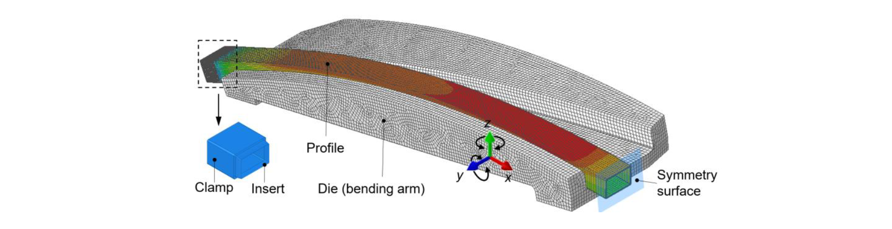
Fig. 4. FE model of stretch bending process.
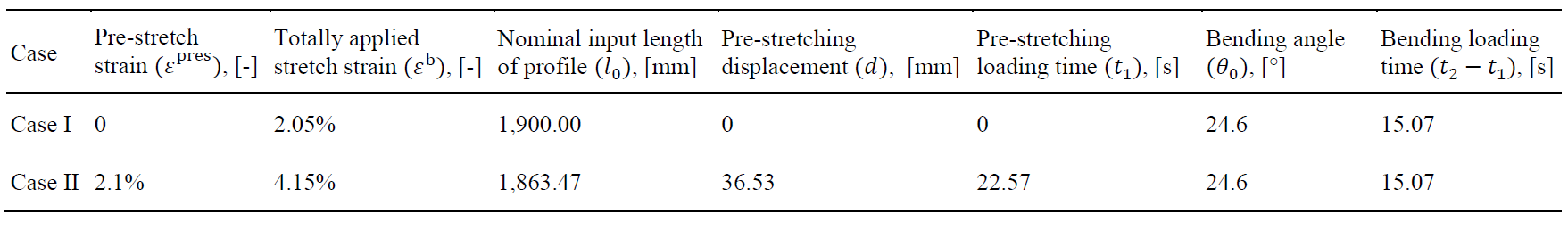
Table 1. Parameters used in forming cases.
FE investigation is conducted to validate the analytical model. Based on Abaqus R2017x, a full-process FE model of pre-stretching and bending is established using the explicit solver. Fig. 4 shows the schematic view of the FE model. Due to asymmetry, only the half model is used. The forming dies, clamp units are modeled as discrete, rigid bodies and meshed by element type R3D4, while the profile is meshed by element type C3D8R with a size of 4 × 3 × 1 mm. The Coulomb friction law with 𝜇=0.2 is used to model the friction between the profile and tools. The Hooke’s law and J2 plasticity model are used to describe the elastic-plastic response of the profile.
In the stretch bending process, the profile is initially stretched to a pre-set length (1,900 mm), and then followed by a combined stretch-bending operation. It should be noted that the geometric locations of the pivots will induce a stretch strain of 2.05% during the combined stretch-bending operation; that is, ε0sb in Eq. (2) equals 2.05%. In this study, two forming cases are conducted and forming parameters are given in Table 1. Case I is forming without applying pre-stretching. Case II is forming with pre-stretching applied, in which the profile is first pre-stretched by 2.10% strain and followed by a combined stretch-bending operation. For comparison, the configuration of the bent parts prior to unloading is exactly the same for the two cases, independent of the (pre-) stretching sequence. As shown in Fig. 2 (d), the length of the mid-straight portion is lms = 44.20 mm, the length of end-straight portion is les = 106.30 mm, the bending radius of the centerline is Rc = 1,827 mm. In analytical calculation and FE simulation, the geometry parameters and process parameters including friction coefficient. For the material parameters, as mentioned before, the engineering stress-strain curve is used to calibrate the parameters for the analytical model, while the true stress-strain curve is used to identify the parameters for FE model since mass conservation is maintained in non-linear FE analysis.
Fig. 5 shows the real-time forming forces obtained by both the developed analytical method (Analytics) and FE method (FEM) for the two forming cases. Before assessment of the analytical model, the characteristics of the forces of the clamp unit and those of the bending die in horizontal and vertical directions are analyzed. For Case I (without pre-stretching applied), the FE simulation shows that the horizontal force of the clamp unit keeps a nearly constant level of about 90 kN when the material enters the elastic-plastic deformation state, as the loading time (or bending angle) increases. The vertical forces of the clamp unit increase near-linearly up to about 45 kN with increasing loading time. As for the bending die, along with the loading time, the horizontal force increases up to about 19 kN at an accelerated rate, while the vertical force is almost the same in value as the vertical force of clamp unit but acting in the opposite direction. For Case II (with pre-stretching applied), in the pre-stretching stage, there is only a horizontal force existing in the clamp unit, which is equivalent to a simple uniaxial tensile process. When the bending operation starts, the overall characteristics of the four forces are similar to Case I, but the corresponding values of the four forces are slightly higher than in case I due to the stress level increased by pre-stretching prior to bending operation.
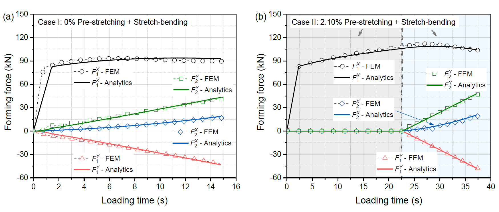
Fig. 5 Comparison of forming forces between analytical calculations and FE simulations: (a) Case I: 0% pre-stretching + bending; (b) Case II: 2.10% pre-stretching + bending.
By comparing the forces between analytics and FE simulations, the accuracy of the developed analytical model can be assessed. It can be found from Fig. 5 (a) and (b) that the analytical model provides highly accurate predictions of the horizontal and vertical forming forces applied by both the clamp unit and bending dies. Taking the highest one (the horizontal force of clamp unit) among the four forces as an example for more detailed analysis, and prediction error during the entire loading cycle can be analyzed as follows: for Case I, except for the elastic deformation stage at the beginning of forming process, the maximum relative prediction error of the analytical model is 4.50%; for Case II, the analytical model gives an even higher prediction accuracy of the real-time force with a maximum relative error of 3.26% during the entire forming process, including the elastic deformation stage at the beginning. As mentioned above, for the process with pre-stretching applied, the whole profile is uniformly deformed in the pre-stretching stage. For the combined stretch-bending process without pre-stretching, however, some local deformation can be induced at the beginning of bending operation, which makes the locally deformed material enters the plastic mode earlier than other portions. As the analytical model does not take such local deformation into account, the prediction accuracy at the beginning stage (elastic deformation stage) cannot be as high as that in the subsequent stable forming stage of the process without pre-stretching applied. It should be noted that such an error has almost no effect on the evaluation of the forming forces since it only occurs in a very short period at the beginning of the process. Therefore, the analytical model proposed herein is claimed to provide an accurate, efficient, and explicit solution for the real-time forming force in the flexible stretching bending process.
5 Conclusions and Outlook
Understanding the real-time forming forces is of fundamental importance to the design and integrated development of product and process in metal forming. In this study, an analytical model is developed for accurate and efficient prediction of the real-time forming forces in a novel flexible rotary stretch bending process, thus providing an effective means to gain insights into the development of forming forces. For the purpose of real-time monitoring, the developed analytical model takes the entire kinematically-controlled loading (strain) history process into account; for instance, the stretch-bending with an additional pre-stretching applied. In addition, the elastic-plastic properties of the material, the profile dimensions, the tooling geometries, including varying curvatures as well as the tool-workpiece friction are comprehensively considered to improve the accuracy of the analytical model. Based on FE simulation, the analytical model is carefully assessed in stretch forming of aluminium rectangular hollow profiles, while applying different pre-stretching levels. The results prove that the analytical model can accurately and quickly predict real-time forming forces throughout the entire process.
Overall, the present model provides an effective means to enhance the understanding of the development of forming forces, thus creating a basis for product design and process control. Even though this study only focuses on the force prediction, the proposed analytical model can be combined into the analytical springback framework that was recently reported by Ma and Welo [1], seeking towards automated, closed-loop feedback control of the process as part of the machine control system. However, the latter needs to establish an integrated steering model to bridge the relations between real-time forces, moment distribution, and springback. Furthermore, an adaptive control strategy requires the successful integration of sensor and vision technologies that provide acceptable accuracy for closed-loop feedback to the control system.
Acknowledgements
The work is supported by Norwegian University of Science and Technology (NTNU), NTNU Aluminium Product Innovation Center (NAPIC), and the KPN Project VALUE (No. 267768) sponsored by the Research Council of Norway, Hydro and Alcoa.
