1 Introduction
Injection molding is one of the most widespread manufacturing process to produce polymeric parts. Typically, molds for mass production are realized with tool steel, ensuring long tool life. The main drawback of such rigid tool is related to the time and costs required for their production, making difficult to overcome the tooling costs in case of prototypal production or small batches [1].
Rapid Tooling was born with the aim of reducing production costs and time, but also for the increasing need of customization of products. Rapid tools are typically obtained through AM (Addittive Manufacturing) thanks to the possibility of obtaining complex shapes and topologically optimized structures with high flexibility. The main drawback is that these parts are typically characterized by a porous structure, limited geometrical accuracy, anisotropic properties and rough surfaces [2].
One of the most versatile, economic and flexible AM technology is FDM (Fused Deposition Modelling). In FDM a preformed polymeric filament is melt and deposed in a fused form through a fine print head called nozzle [3].
Most of the commercial FDM devices are used with ABS or PLA, but a large variety of polymers is commercially available in the market. Depending on the complexity of the part, some supporting structures might be required. Also, post-processing treatments like surface finishing or thermal treatments could be necessary [4].
Chua et al. in their work (Ref. [4]) reported an example of ABS moulds employed for wax injection molding at pressures and temperatures of 1.38 MPa and 66 °C respectively. Similarly, Masood et al. (Ref. [5]) realized inserts starting from a composite filament made of iron particles in a nylon matrix; high quality plastic parts have been injection molded using the inserts. The authors highlighted also the possibility to reduce the cost and time in rapid tooling.
If on one hand polymeric tools produced with FDM allows to reduce production cost and time, on the other hand such tools typically suffer from common problems: creep, limited mechanical properties, thermal degradation, reduced tool life, longer cooling time and rough surfaces [6].
In literature there are not so many examples of polymeric molds produced through FDM and potentially there are a lot of materials not tested yet. Moreover, there is not a defined methodology for selecting the optimal polymeric material for the mold. In this work, after an analysis of the commercially available FDM filaments, with the aim of reducing the existing limits of FDM tools, a material selection methodology has been proposed. Specifically, the injection of a Polypropylene part is considered as case study. The material selection was based on tool cost minimization considering thermo-mechanical constraints. In the end, the material selected was a PEI grade. Some samples of the PEI have been 3D printed with FDM using different 3D printing strategies and then characterized with: DSC (Differential Scanning Calorimetry), DMA (Dynamic Mechanical Analysis) and compression tests at three different temperatures (25°C, 150°C and 200°C). The characterization tests were needed to build a 2D finite element model to simulate the thermo-mechanical response of the PEI inserts under cyclic injections of Polypropylene.
Later, some PEI inserts have been 3D printed tested, producing in total 20 POM parts. The polymeric inserts did not show any relevant damages during molding.
2 Material selection
The injection of a Polypropylene part processed with an injection time of 2s, a melt temperature of 240°C and packing pressure of 40 MPa was considered as case study The properties relevant for the material selection have been identified in:
-
Young’s modulus (E). This material property should be maximized to limit the elastic deformations.
-
Compression strength (σc). This material property should be high enough to avoid failure under compression (which is a typical state of stress for molds).
-
Thermal diffusivity (a). This material property should be as high as possible to reduce the cooling time of the injected material and to avoid the progressive heating of the mold cycle after cycle.
-
Maximum service temperature (Tmax). This material property should be maximized in order to avoid the thermal degradation of the tool.
-
Glass transition temperature (Tg). During the molding process, the temperature of the tool should be always at least ≈ 20°C lower than Tg to avoid a sudden drop in the stiffness.
-
Cost per unit volume of the FDM filament (Cv). This material property is given by the product of cost per unit mass (Cm) and density (ρ) and should be minimized.
Considering the listed material properties and the specific case study, the maximum service temperature of polymers commercially available as FDM filament has been used as first screening. The polymeric materials potentially suited for the application are reported in Fig. 1. To determine the best one, for each material two indexes have been identified according to Ashby’s method: I1 and I2 (see Fig. 1). Those indexes are defined according to Equation (1).

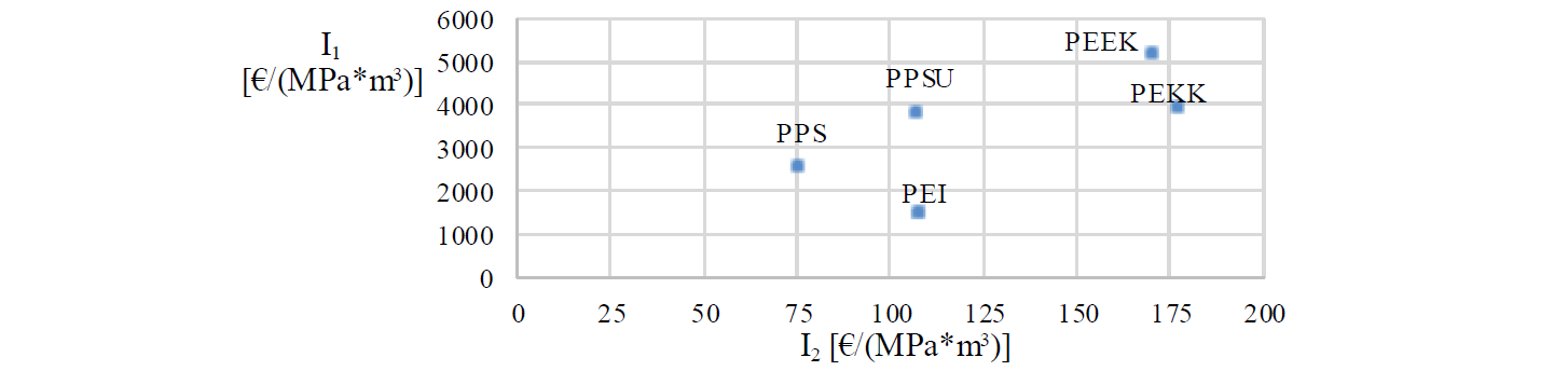
Fig. 1: I1 and I2 for the five materials found.
The preliminary study reported in Fig. 1 showed that PPS and PEI are the best candidate materials (i.e. with smallest I1 and I2). To decide between the two materials, the high temperature Young’s modulus has been considered as main discriminant (see Fig. 2).
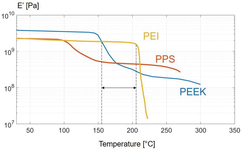
Fig. 2: Conservative component of the Young’s modulus (E’) vs temperature for PEI, PPS and PEEK.
Considering the high temperature Young’s modulus, the PEI resulted to be the best candidate tooling material. The commercial name of the PEI grade is Ultem 1010.
3 3D printing and characterization of the PEI
Some specimens of the PEI have been 3D printed with different 3D printing orientations but with constant process parameters reported in Table 1. The infill was set to 100% and a cross laminated ±45° alternated layer strategy was used.
Table 1: 3D printing process parameters.
|
Layer height [mm] |
Nozzle diameter [mm] |
Extruder temperature [°C] |
Bed temperature [°C] |
Print speed [mm/s] |
|
|
Value |
0.25 |
1.75 (+/- 0.05) |
370-390 |
120-160 |
25 |
The 3D printed specimens were characterized with: DSC, DMA and compression tests. The 3D printing orientation did not induce relevant variations on the measured properties, meaning that the printing process is repeatable and isotropic properties are obtained (see Fig. 4). The characterization tests were needed to set up a finite element model, describe in Paragraph 4.
Differential Scanning Calorimetry (DSC): DSC was needed to define the temperature-dependent specific heat capacity of the PEI. The obtained values were implemented in a FEM (see Paragraph 4). The results of the DSC analysis confirmed the nominal values of specific heat capacity (Cp) and glass transition temperature (Tg=217°C).
The thermal conductivity of the PEI has been considered constant in the range of temperature in order to simplify the FE model.
The value of the thermal conductivity is reported in Table 2.
Dynamical Mechanical Analyses (DMA): the DMA test allow to characterize the temperature-dependent behavior of the PEI in the elastic regime at a fixed frequency (see Fig. 3). The properties that can be measured in such test are the conservative and dissipative component of the Young’s modulus and the loss factor (tan(δ)).
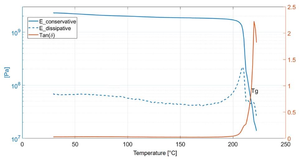
Fig. 3: Results of the DMA test (frequency 1 Hz).
Compression tests: The compression tests have been performed onto cylindrical specimens printed with two different printing orientations, as shown in Fig. 4. The PEI has been tested at 25°C, 150°C and 200°C with an imposed displacement rate of 1 mm/min.
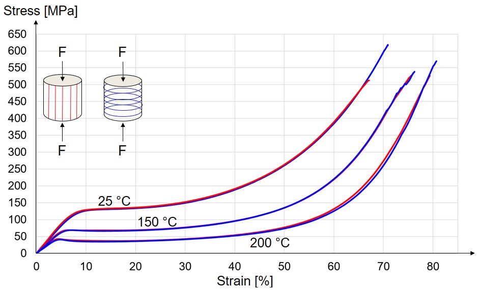
Fig. 4: Results of the compression tests: true stress vs true strain (1 mm / min) for the two different printing strategies.
4 2D simulations
Material properties and mesh: 2D finite element analyses (Abaqus) have been set up so simulate the thermo-mechanical response of the PEI inserts under cyclic injections of Polypropylene. The model is a clear simplification of the real process but it has provided a lot of interesting conclusions. The material properties required to set up the simulations are summarized in Table 2.
Table 2: Material properties needed to set up the FEM. 𝛼 is the volumetric thermal expansion coefficient, 𝜈 is the Poisson coefficient, 𝐾𝑇 is the thermal conductivity.
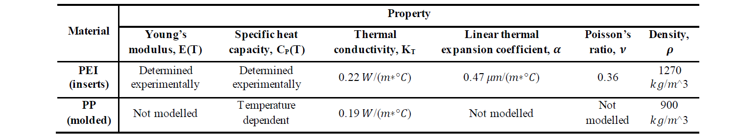
The temperature-dependent data of the specific heat capacity for PP was obtained by the commercial software Moldflow (Autodesk). This property is approximately equal and constant to 2000 J/(kg K) apart from a peak value of 15000 J/(kg K) achieved around 125 °C (in correspondence of the glass transition temperature).
The Young’s modulus of the PEI (|E∗(𝑇)|) has been computed according to Equation (2) from the measured values of the conservative (𝐸′(𝑇)) and dissipative (𝐸′′(𝑇)) components of the Young’s modulus (Fig. 3).

The values of 𝛼, 𝜈 and 𝐾𝑇 for the PEI and PP were obtained from the material database software CES EduPack. The geometry modelled is reported in Fig. 5. Because of symmetry and considering a plane strain problem, only one half of the 2D part has been considered: it is assumed that no deformation occurs along the direction Z (Fig. 5). The elements used for this simulation are CPE4T type (4-node bilinear displacement and temperature elements). The total number of elements is 93400 and the mesh size (cavity) is 0.025 mm (ensure the convergence of the numerical result).
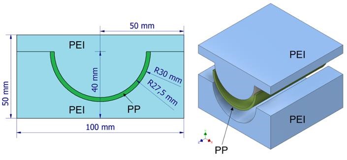
Fig. 5: 2D (left) and 3D (right) drawing of the Polypropylene part (green) in between the PEI inserts (blue).
Definition of the cycle and boundary conditions: The injection molding cycle was defined in this way:
-
Step 1 – injection (Fig. 6-a): this step has a fixed duration of 2 seconds. At the beginning of each cycle the Polypropylene is at 240°C and starts cooling down due to the contact with the PEI tools: the flow of polymer is not modelled and the polymer is assumed to fill the cavity instantaneously. Therefore, just conduction transfer is modelled. For the entire duration of this step, the core of the Polypropylene part (red dashed line in Fig. 6-a) has a fixed temperature of 240°C. This simulates a constant temperature of the core during the injection process. At the end of this step, this thermal boundary condition is removed. For the first cycle, the initial temperature of the inserts is 20°C.
-
Step 2 – cooling (Fig. 6-a): this step has a variable duration and finishes when the hottest point in the Polypropylene reaches 120°C; at this temperature the molded material is considered stiff enough to be extracted without permanent deformations.
-
Step 3 – open mold (Fig. 6-b): this step has a fixed duration (10 s). The Polypropylene in this step is not present and the mold is able to cool down due to the upper and lower thermal boundary conditions (T=10°C). Moreover, the green surfaces are able to exchange heat through natural air convection (the sink temperature is 20°C and the heat convection coefficient is 20 W/(m2K)).
During step 1 and step 2, a uniform pressure of 40 MPa is applied onto the yellow surfaces (Fig. 6-a).
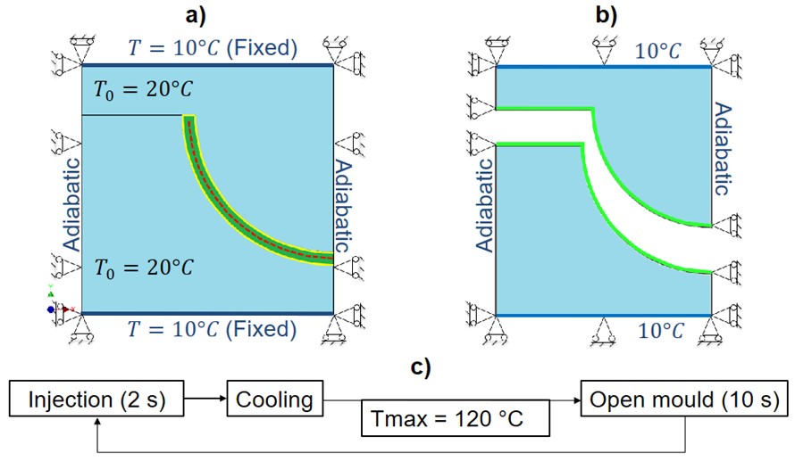
Fig. 6: Thermomechanical boundary conditions during “injection + cooling” (a) and “open mold” configuration (b). c) Scheme of two consecutive injection cycles.
Results of the simulations: the FEM clearly present some limitations but can be used to understand the feasibility of using a specific material to produce inserts for injection molding. The most relevant results are summarized:
-
Cycle by cycle both the cooling time of the Polypropylene part and the cavity surface temperature increase till a regime condition (see Fig. 7-a and Fig. 7-b).
-
The maximum temperature achieved by the PEI tool during the process is ≈ 180°C (see Fig. 7-b), meaning that the material is still thermally stable and stiff, without any need of a protective coating.
-
During all cycles the inserts work in the elastic regime (see Fig. 7-c), but the cavity pressure of 40 MPa introduces a variation of the thickness of the molded part (see Fig. 7-d).
In conclusion, the simulations confirmed that the material selected is thermally and mechanically stable for the application. On the contrary, PEI inserts, as all polymeric inserts, have a much lower stiffness and thermal diffusivity with respect to metallic tools. This limits the applicability of such materials only for prototypal applications or small batches.
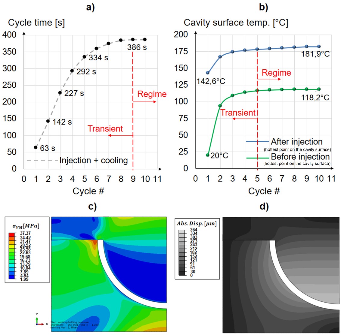
Fig. 7: a) Evolution of the cycle time (injection + cooling time) during the molding of a 2.5 mm thick Polypropylene part. b) Evolution of the hottest point of the cavity surface during consecutive cycles before (green) and after (red) injection (step 1). c) Von Mises stresses at the regime cycle at the end of the injection (step 1). d) Absolute displacement in [𝜇𝑚] of the polymeric inserts at the regime cycle at the end of the injection (step 1).
5 3D printing and testing of PEI inserts
Clearly, the finite element model presented is just a simplification of the reality and it is not sufficient to demonstrate the applicability of the PEI as tooling material for injection molding. In order to prove that, two PEI inserts (movable and fixed molds) have been realized through FDM and mounted in a real injection molding machine. The material injected is a POM grade. Such experiments must not be considered as validation tool of the previous simulations but only as confirmation of the thermal stability of the PEI.
The 3D printed inserts contain all the typical features of a conventional metallic mold (Fig. 8): the sprue, the runner, the gate, the cavity, guiding holes, cooling channels, holes for ejector pins, and a conical hole to mount the metallic sprue bushing.
The sprue bushing is the element used to connect the female insert to the nozzle of the injection molding machine and allows to converge the flux of fused polymer into the sprue. Moreover, by means of the metallic sprue bushing, the PEI is never in a direct contact with the nozzle of the injection molding machine, thus avoiding thermal degradation issues.
Both the inserts have been 3D printed with a growing direction parallel to Z axis (Fig. 8). This direction was chosen in order to have the best surface quality in the cavity but this requires the presence of supporting material for the guiding holes and for the cavity for the sprue bushing (Fig. 9). The cooling channels did not require any supporting structure. The FDM process parameters and printing strategy used are the same of the ones reported in Paragraph 3.
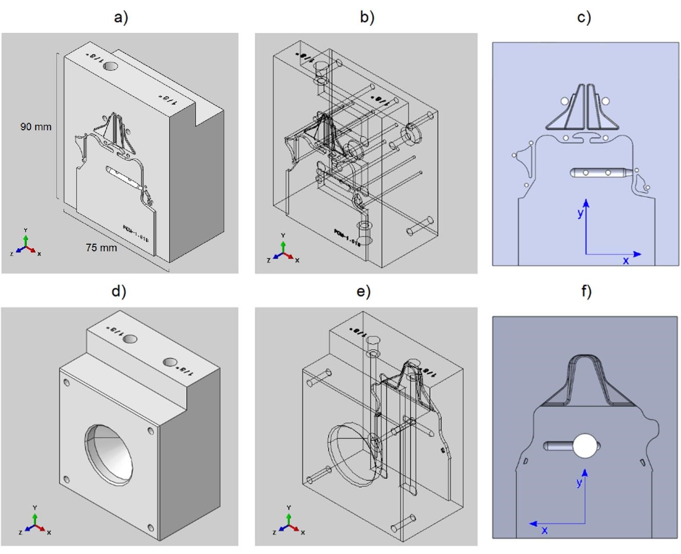
Fig. 8: a) Solid view of the movable insert. b) Internal features of the movable insert. c) Front view of the movable insert. d) Solid view of the fixed insert. e) Internal features of the fixed insert. f) Front view of the fixed insert. The maximum thickness of the cavity (i.e. of the molded part) is 1.5mm.
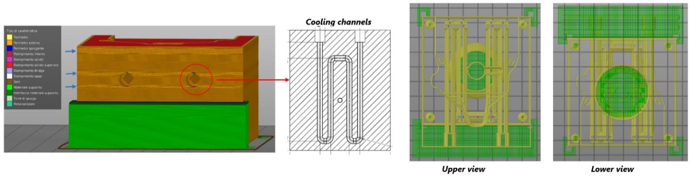
Fig. 9: Left: supporting structures (green) and PEI insert (brown), highlighting the presence of internal features. Right: upper and lower view of the supporting structures (green) and internal features (yellow) of the fixed insert.
The process parameters used to inject the POM are reported in Table 3. During the process, the cooling system was active and water was pumped into the cooling channels at a pressure of 5 bar.
Table 3: Process parameters used in the injection molding process.
|
Melt temperature [°C] |
Initial mold temperature [°C] |
Injection time [s] |
Packing time [s] |
Cooling time [s] |
Cycle time [s] |
Packing pressure [MPa] |
|
|
Value |
225 |
20 |
1 |
2.5 |
4 |
13 |
25 |
The inserts were mounted in an injection molding machine and during the process, the injection pressure and the maximum clamping force were measured, resulting respectively equal to 50 MPa and 200 kN. The inserts were tested initially with the cooling system active (water circulating at 5 bar). Because of capillarity, the pressurized water circulating in the cooling system after few injection cycles permeated through the inserts emerging on the external surfaces. Despite the 100% infill used during the FDM process, the permeation of water indicated the presence of residual porosity in the tools. This unexpected problem can be easily solved by turning-off the cooling system or applying a thin and compact coating on the surfaces of the cooling channels.
In this case the inserts were tested again with the cooling system inactive, producing consecutively 20 POM parts (Fig. 10-c).
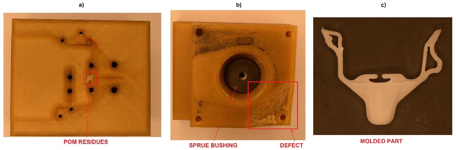
Fig. 10: a) Some POM residues present on the surface of the movable insert. b) Damage observed in the fixed part while dis-mounting the tool. c) Molded part without the sprue (mechanically removed). The molded part covers an area of 75 mm x 55 mm. The maximum thickness of the molded part is 1.5 mm.
At the end of the 20 molding cycles, a small damage at one corner of the fixed part was observed (Fig. 10-b). The damage was already present before dis-mounting the insert, indicating a possible damage due to the high clamping force.
As consequence of the FDM printing process, the surface of the tools is not completely smooth, resulting into a rough surface of the molded part (Fig. 10-c). This made difficult for some parts the ejection from the mold.
6 Conclusions and future works
A procedure for material selection of polymeric rapid tools for injection molding has been proposed, considering as case study the injection of a Polypropylene part. The tooling material selected is Ultem1010, a PEI grade commercially available for FDM. Some PEI samples were 3D printed and characterized through DSC, DMA and compression tests. The acquired data were then implemented into a FE solver to simulate the thermo-mechanical response of PEI inserts subjected to consecutive injection molding cycles. According to the simulations, the PEI resulted thermally stable but not suitable for mass production of Polypropylene parts due to prolonged cooling times and due to the elastic deformations of the inserts.
Later, two PEI inserts were printed through FDM, mounted in an injection molding machine and tested, producing in total 20 POM parts consecutively. The tests were not meant as validation of the simulations, but as proof of the thermal stability of Ultem1010 and possible applicability in injection molding. The inserts did not show relevant damages but other problems were observed: difficult de-molding of the POM parts and water permeation through the inserts when the cooling system is active.
Future works will be focused on solving the problems observed during molding: polishing the surfaces of the cavity to ease the ejection phase and applying a compact and thin coating on the surfaces of the cooling channels to avoid water permeation.
