1 Introduction
The deep drawing of cylindrical cups is commonly used to evaluate the performance of constitutive models, namely the recently developed advanced yield criteria [1]. The accurate prediction of the earing profile arising in cylindrical cups is strongly dictated by the in-plane distribution of both the directional r-values and the tensile yield stresses. Therefore, the yield surface used in the numerical model to describe the sheet orthotropic behavior plays a significant role in the predicted earing profile. The number of material parameters used to define the yield functions has been increasing to improve the fitting with the experimental data. Alternatively, in order to overcome the limitations of the usual associated flow rule, some studies are focused on the development of non-associated flow rules [2], aiming superior accuracy of fit and convergence rate during simulation. Nevertheless, the advantages of using a nonassociated flow rule are not consensual. In this study, an associated flow rule is adopted.
The flange wrinkling can occur in deep drawing of cylindrical cups, particularly for low values of blank holder force. It is a result of large compressive circumferential stresses arising in the flange, as consequence of the large blank draw-in (small radial tensile stress component). Due to the local buckling nature, the rise and growth of wrinkles are influenced by many factors, including the material anisotropy, tooling geometry, contact conditions and stress state [3]. Besides, the reliability of the numerical solutions provided by the finite element method are significatively influenced by several numerical parameters, such as finite element type, mesh refinement, kinematic formulation of the problem, time integration, etc. [4,5]. Therefore, the predicted wrinkling behavior can be different in terms of number, distribution and shape of wrinkles.
The formability limit is typically determined using the forming limit diagram, allowing to define the strains associated with the occurrence of localized necking. Nevertheless, the fracture can occur either with or without severe strain localization, requiring the development of alternative models capable of predicting the formability limits. Typically, these models take into account the constitutive model that best describes the material mechanical behavior. Thus, the yield criterion adopted plays an important role, particularly when an associated flow rule is adopted [1].
2 Numerical model
2.1 Cup drawing and embossing
The forming example adopted in this study is the deep‐drawing of an axisymmetric cup, which was proposed under the Numisheet 2018 international conference [6]. The circular blank presents a diameter of 246 mm and a thickness of 2.8 mm. Then blanks were cut from a hot rolled steel sheet (SAPH 440 in Japanese Industrial Standard). Three different process conditions are analyzed in this study, which are designated as Task 1, Task 2 and Task 3, according to the benchmark description [7]. The setup of the forming tools used in each task is schematically shown in Fig. 1.
In Task 1 (see Fig. 1 (a)), the die moves downwards, while the stripper applies a force of 50 kN to the blank (kept constant during the forming) and the lifter applies a force of 70 kN to the flange area of the blank (kept constant during the forming). The geometry of the forming tools used in Tasks 2 and 3 is presented in Fig. 1 (b), where the lifter disappears, and the punch shape is modified to include a center boss. In Task 2 the die moves downwards up to 23.2 mm of height above the bottom dead center of the die, i.e. the center boss in negligible. On the other hand, in Task 3 the die moves downwards until fracture occurs at the apex of the center boss. In order to reduce the friction forces, lubricant was applied to both surfaces of the blank, stripper, punch, die and lifter contacting surfaces.
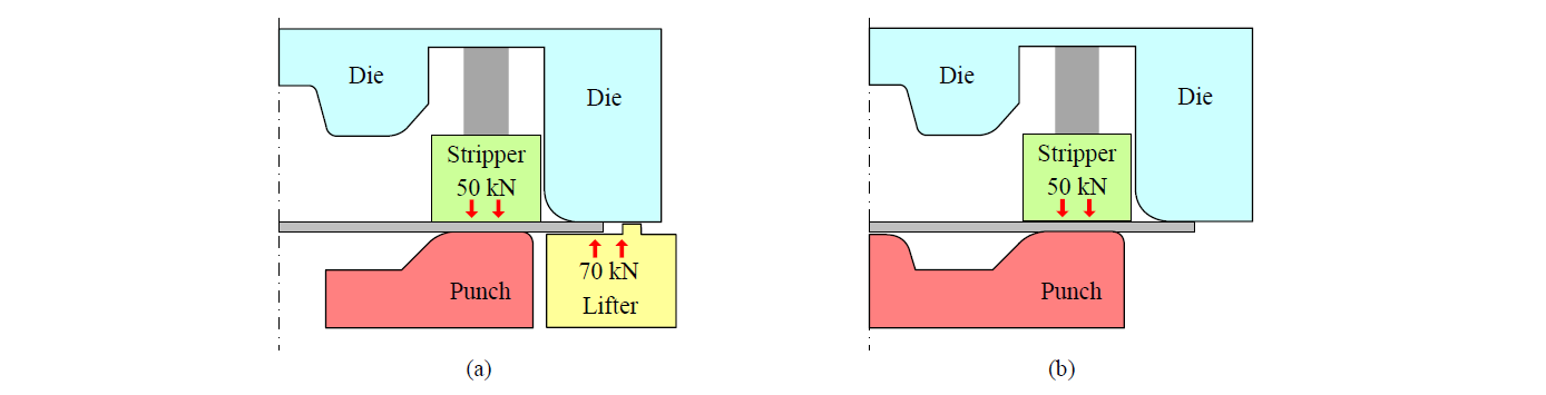
Fig. 1. Schematic illustration of the forming tools used in the cup drawing: (a) Task 1; (b) Task 2 and 3.
2.2 Finite element model
The numerical simulations were performed with the in-house finite element code DD3IMP [8], assuming that the forming tools are rigid and modelled by Nagata patches [9]. The Coulomb friction law is adopted, considering a constant friction coefficient value of 0.15, as recommended by the benchmark committee [7]. Taking into account the geometry and material symmetry conditions, only one-quarter model is simulated. The discretization of the blank with linear hexahedral finite elements (4 layers through the thickness) is presented in Fig. 2. As shown in the figure, for each task, the discretization adopted takes into account the zones of the blank with more plastic deformation. The rolling direction (RD) is initially aligned with the Ox-axis.
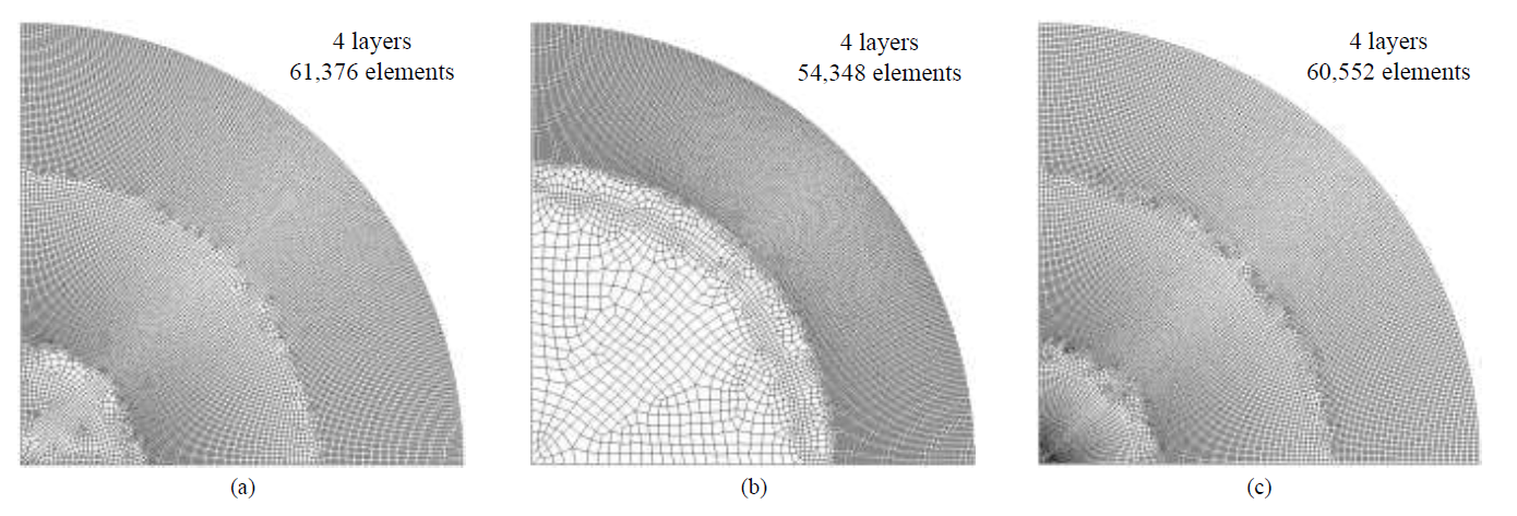
Fig. 2. Discretization of the blank with hexahedral finite elements: (a) Task 1; (b) Task 2; (c) Task 3.
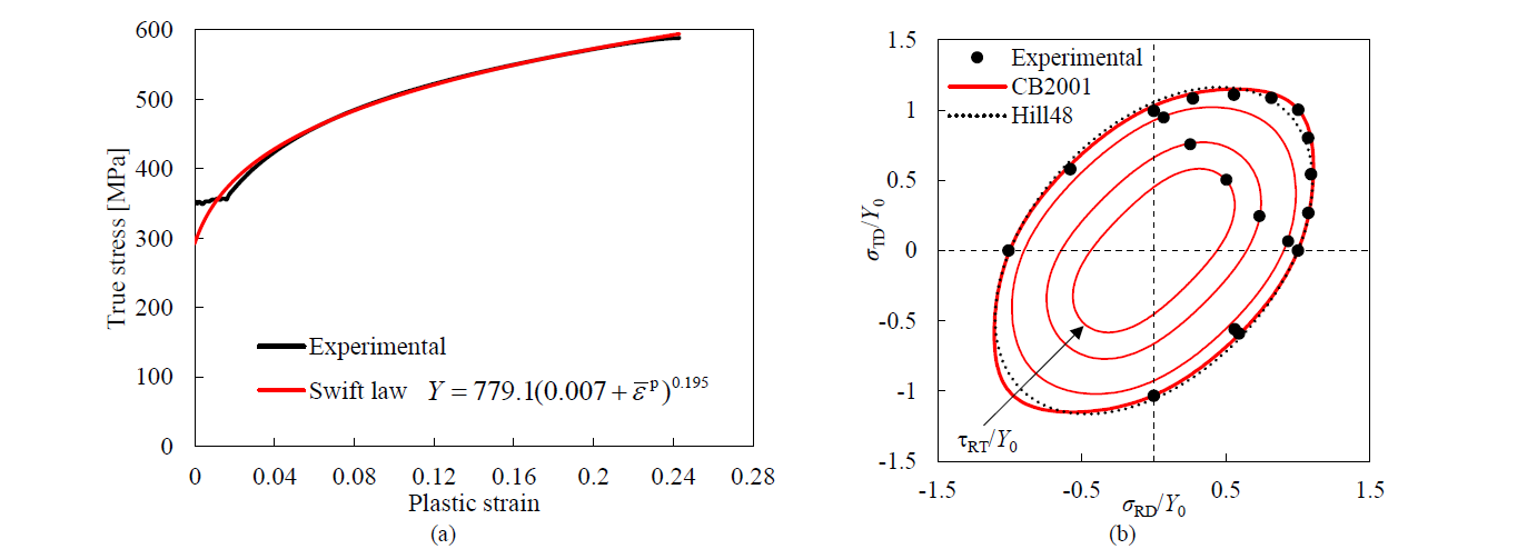
Fig. 3. Plastic behavior of the SAPH 440 steel sheet: (a) true stress–equivalent plastic strain curve and hardening law fitted from the uniaxial tensile test in the rolling direction; (b) normalized projection of the yield surfaces in the σRD-σTD plane, with null values for all the other stress components. For the CB2001 yield criterion, the projections are also shown for the levels of the shear stress component in the plane of: 0.25Y0; 0.4(3)Y0 and 0.50Y0.
The mechanical behavior of the steel sheet (SAPH 440) is considered elastoplastic. The elastic behavior (isotropic) is defined by the generalized Hooke’s law, considering the Young’s modulus E=206 GPa and the Poisson’s ratio ν=0.3. Regarding the plastic response, the isotropic work hardening behavior is modelled by the Swift law, while the orthotropic behavior is modelled by the yield criterion proposed by Cazacu and Barlat [10], commonly designated as CB2001. The experimental true stress–equivalent plastic strain curve obtained from the uniaxial tensile test performed along the RD is presented in Fig. 3 (a), which was used to fit the parameters of the Swift law, neglecting the initial plateau. The yield criterion CB2001 is based in the generalization of the invariants of the deviatoric stress tensor to orthotropy, where the equivalent stress is given by:

where J20 and J30 are the second and third generalized invariants of the effective deviatoric stress tensor, respectively. The second invariant generalized to orthotropy is defined by:

where ai (i=1,...,6) are anisotropy coefficients. The third invariant generalized to orthotropy is defined by:
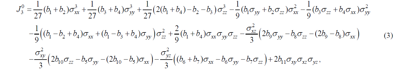
where bi (i=1,...,11) are anisotropy coefficients. Although this yield criterion involves 18 material parameters, the parameters a5, a6 and bi (i=6,7,8,9,11) cannot be evaluated for metal sheets. Thus, isotropy condition values are commonly adopted for these parameters, i.e. 1.0.
The calibration of the 11 anisotropy parameters was performed using the in-house code DD3MAT [11], which is based on the minimization of an error function that evaluates the difference between the experimental and predicted values [12]. The set of experimental data used in the calibration of the anisotropy parameter comprises: (i) uniaxial tension data (in-plane distribution of the yield stress and r-values) extracted from tests performed in every 15º to the RD and (ii) data from biaxial tension tests, used to evaluate the directions of the plastic strain rates for the first quadrant of the yield loci. The set of experimental data used in this work corresponds to the one reporter for a plastic work per unit volume of 0.05 [6]. Since the conditions that guarantee the convexity of CB2001 are unknown, the minimization process includes testing the convexity of the yield surface, for several planes in the stress space [13]. The obtained material anisotropy parameters are listed in Table 1. Fig. 3 (b) presents the projection of the yield surface in the RD-TD plane, with null values for all the other stress components, and the experimental points from the biaxial tension tests, as well as the ones extracted from the uniaxial tensile tests. In this context, the projections of the yield surfaces are also plotted assuming different values of the in-plane shear component, corresponding to the ones observed in the uniaxial tensile tests. The yield surface obtained with the Hill’48 yield criterion, identified using the r-value for the uniaxial tensile tests performed at 0º, 45º and 90º, is also presented. The comparison is performed for this yield criterion because it is commonly adopted for describing the orthotropic behavior of steels. The comparison between experimental and numerical results of the normalized uniaxial yield stress values and the Lankford coefficients are presented in Fig. 4 (a) and (b), respectively. Fig. 4 (c) presents the comparison between the experimental and numerical results of the distribution of the direction of the plastic strain rate, in function of the loading direction. Globally, the CB2001 yield surface is in good agreement with the experimental values, particularly for the plastic strain ratio distribution (Fig. 4 (b)) and the distribution of the direction of the plastic strain rate (Fig. 4 (c)). The main differences in the distribution of the direction of the plastic strain rate predicted with both yield criteria occurs for the loading directions located between the plane strain (in RD or TD) and the biaxial stress state.

Table 1. Material parameters used in the CB2001 yield criterion to model the anisotropic behavior of the SAPH 440 steel.
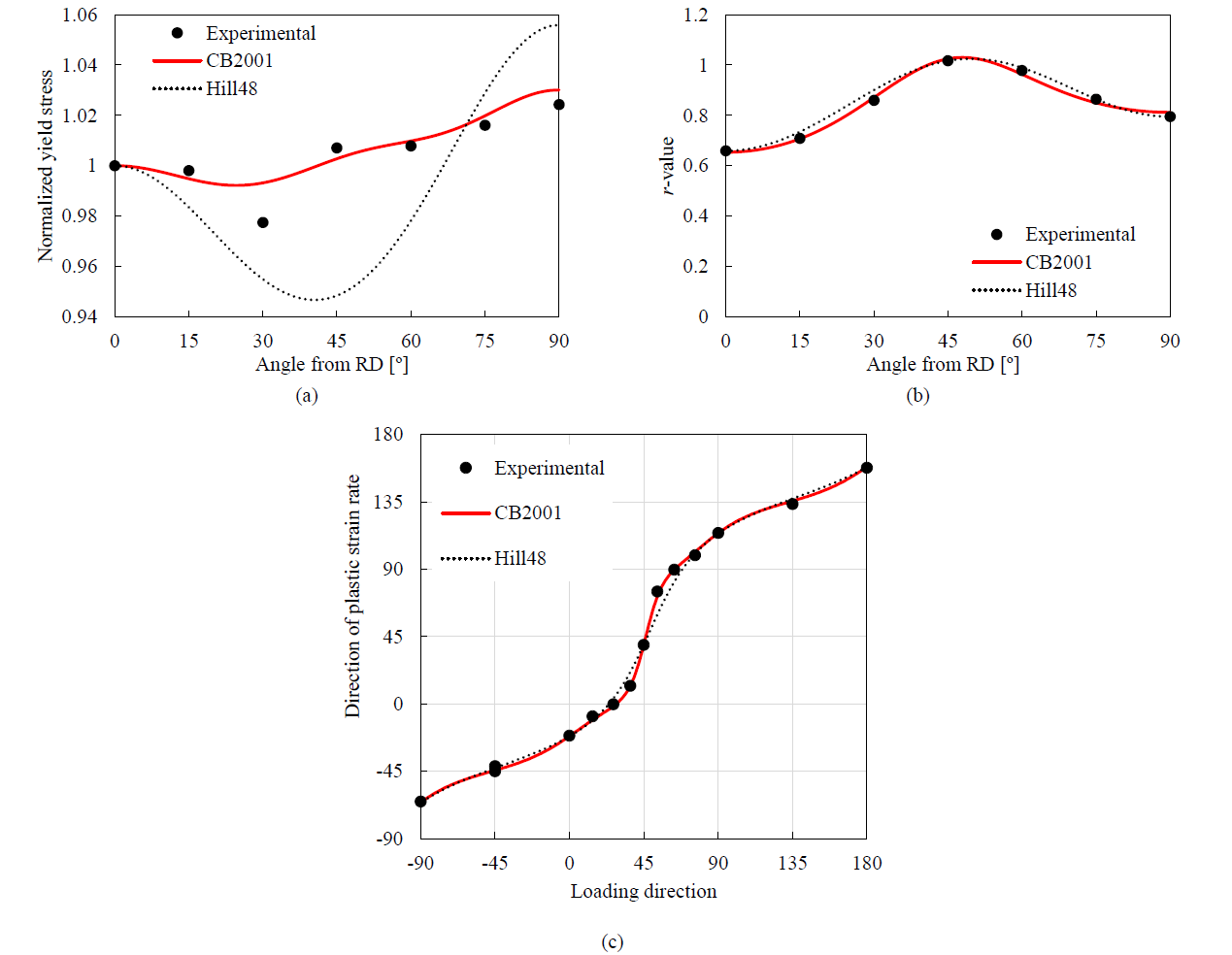
Fig. 4. Comparison between experimental and predicted: (a) distribution of the normalized yield stresses in the sheet plane; (b) distribution of the r-values in the sheet plane; (c) distribution of the direction of the plastic strain rate in function of the loading direction.
3 Results and Discussion
3.1 Earing profile (Task 1)
The comparison between experimental and predicted forming force (die+stripper, see Fig. 1 (a)) evolution is presented Fig. 5 (a), highlighting the different stages of the forming process. The first stage comprises only the bending-unbending of the blank flange over the punch shape, which occurs up to approximately 35 mm of die displacement. Afterwards, the embossing stage takes place in the cup bottom (see Fig. 5 (a)), which leads to an increase of the forming force. Although the forming force is globally overpredicted, the numerical result is in good agreement with the experimental measurements (4 tests under identical conditions).
Fig. 5 (b) presents the comparison between the experimental and the numerically predicted cup height, measured around the circumferential direction. The number of ears (4) is accurately predicted, while the amplitude of the earing profile is overpredicted by the numerical model. Although the maximum cup height is accurate predicted (within the noise range observed in the experimental data), the cup height in the valleys of the earing profile is underpredicted, particularly in the transverse direction, as shown in Fig. 5 (b). The mechanical behavior for the material located along this direction is mainly dictated by the one observed for the uniaxial tensile test performed along RD. Moreover, Fig. 4 (a) indicates that the in-plane variation of the yield stresses is underestimated by the CB2001 yield criterion. Therefore, it is not evident the reason for the overestimation of the earing amplitude. Indeed, both the r-values and yield stresses profile are important for the earing profile prediction [14]. The fact that the forming force is overestimated indicates that the contact with friction conditions maybe affecting the earing profile.
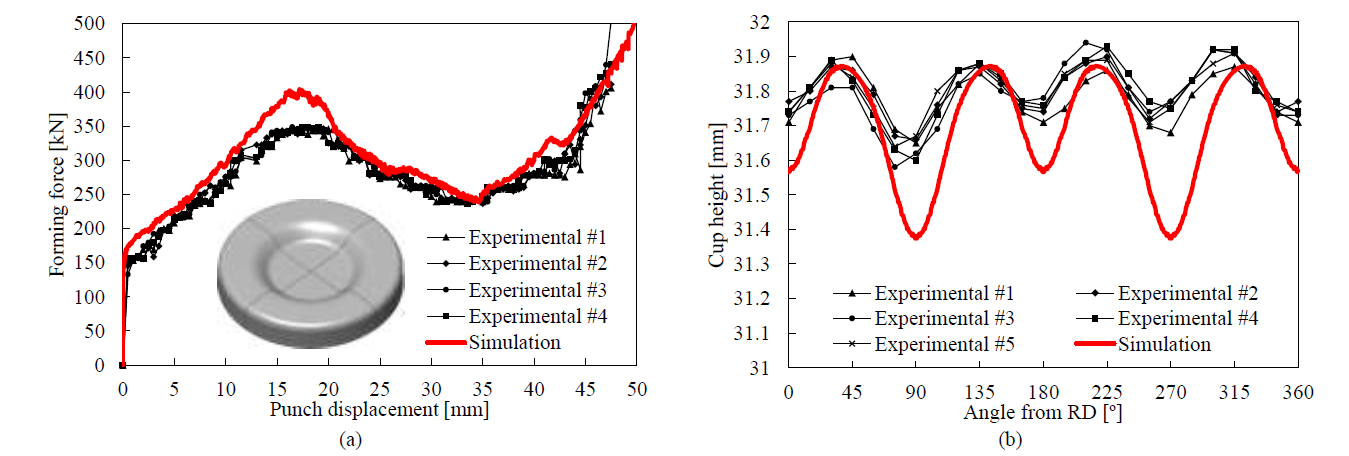
Fig. 5. Comparison between experimental measurement and numerical prediction in Task 1: (a) forming force evolution; (b) earing profile.
3.2 Springback (Task 1)
The comparison between experimental and predicted cross section of the cup after springback is presented in Fig. 6. The profiles were measured on the inner surface (punch side) of the cup along the RD (Fig. 6 (a)) and along the transverse direction (Fig. 6 (b)) of the blank. The numerical predictions are in very good agreement with the experimental measurements since the springback is very low in this axisymmetric component. Indeed, the final geometry of the cup is mainly dictated by the geometry of the forming tools (see Fig. 1 (a)). Therefore, the difference between the experimental and the numerical cup geometry after springback is negligible. Nevertheless, Fig. 6 includes a detail of the cup profile highlighting the accurate prediction of the slope of the cup’s bottom, which can be an important aspect when dealing with the assembly of this type of components. The residual hoop stresses developed in the cup wall during the drawing operation (tensile at the outer surface and compressive at the inner surface) are not relieved after springback due to the constrains imposed by the cup geometry [15].
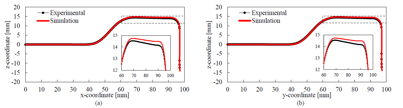
Fig. 6. Comparison between experimental and predicted springback in Task 1: (a) cup profile in the xOz plane; (b) cup profile in the plane transverse to the rolling direction (yOz).
3.3 Wrinkling in the cup wall (Task 2)
Fig. 7 (a) presents the comparison between experimental and numerically predicted radial coordinate along the circumferential direction, evaluated after springback in the inner surface at 25 mm from the cup base. The process conditions in Task 2 comprise the cup drawing without lifter (see Fig. 1 (b)), which leads to the development of some wrinkles in the flange, since it is unsupported during the bending process. The experimental shape of cup after springback is shown in Fig. 7 (b), highlighting the wrinkles developed in the flange. The amplitude of wrinkles is significantly underestimated by the numerical model, as shown in Fig. 7 (a). In fact, the wrinkling amplitude measured in the experimental cups is about 4 mm, while the numerical prediction provides an amplitude lower than 1 mm. As shown in Fig. 2 (b), the discretization adopts a small element size (about 0.8 mm of length in the circumferential direction) for the zone of the flange. Nevertheless, the use of a static implicit approach makes it difficult to predict the initiation of the wrinkles, without introducing an initial imperfection [16]. The number of wrinkles observed in three identical cups range between 15 and 18, while the numerical simulation predicts 16 wrinkles. Therefore, the proposed model accurately predicts the number of wrinkles.
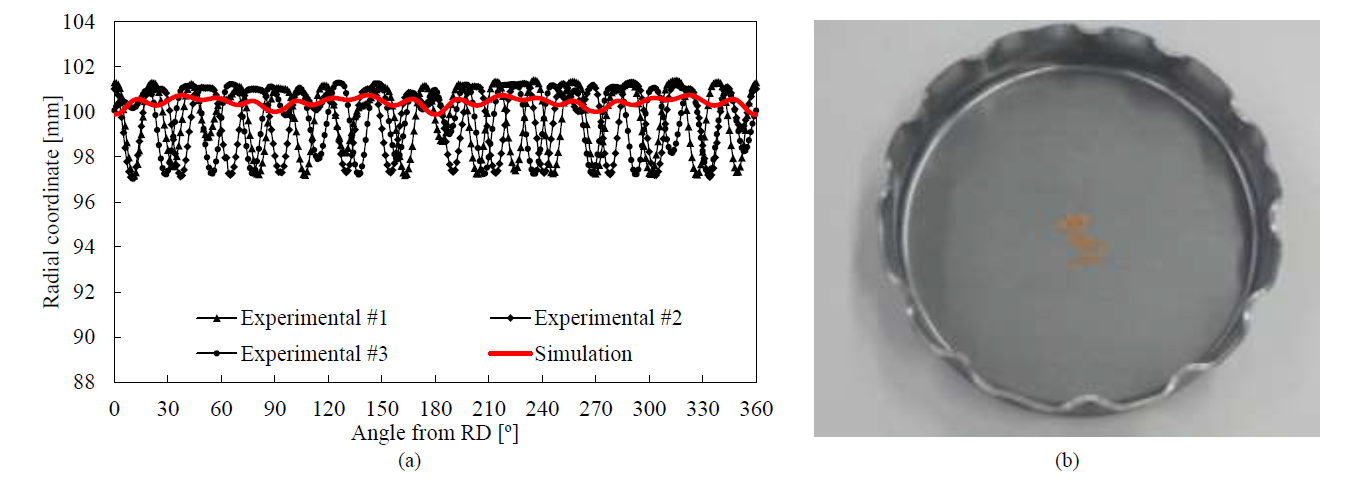
Fig. 7. Analysis of cup wall wrinkling in Task 2: (a) comparison between experimental and predicted radial coordinate evaluated in the inner surface at 25 mm from the cup base; (b) geometry of the cup with wrinkles.
3.4 Tearing in the center boss (Task 3)
The comparison between the experimental and the predicted evolution of the minimum thickness in the apex of the center boss is presented in Fig. 8 (a). The numerical prediction is in very good agreement with the experimental measurements, i.e. the difference is inferior to 4%. The thinning occurs predominantly in the apex of the center boss, due to the conditions imposed by the geometry of the forming tools. First, the cup wall is formed through the downward movement of the die (see Fig. 1(b)), which creates significative restraining forces in the periphery of the cup during the embossing operation. Therefore, the radial strain generated by the die in the cup bottom is accompanied by the thinning of the blank in the region of the center boss. The minimum thickness is reduced from 2.8 mm down to 0.85 mm when the gap between the punch and the die is roughly the blank thickness. The fracture is observed experimentally in the range 2.6<H<3.6 mm, as shown in Fig. 8 (a) through the dispersion in the measured thickness value. The geometry of the cup is presented in Fig. 8 (b) for H=3.6 mm, i.e. immediately before the fracture. The predicted thickness strain is mainly located at the apex of the center boss, which agrees with the necking observed in the experimental cup. These results highlight the importance of the plasticity model in the prediction of ductile fracture.
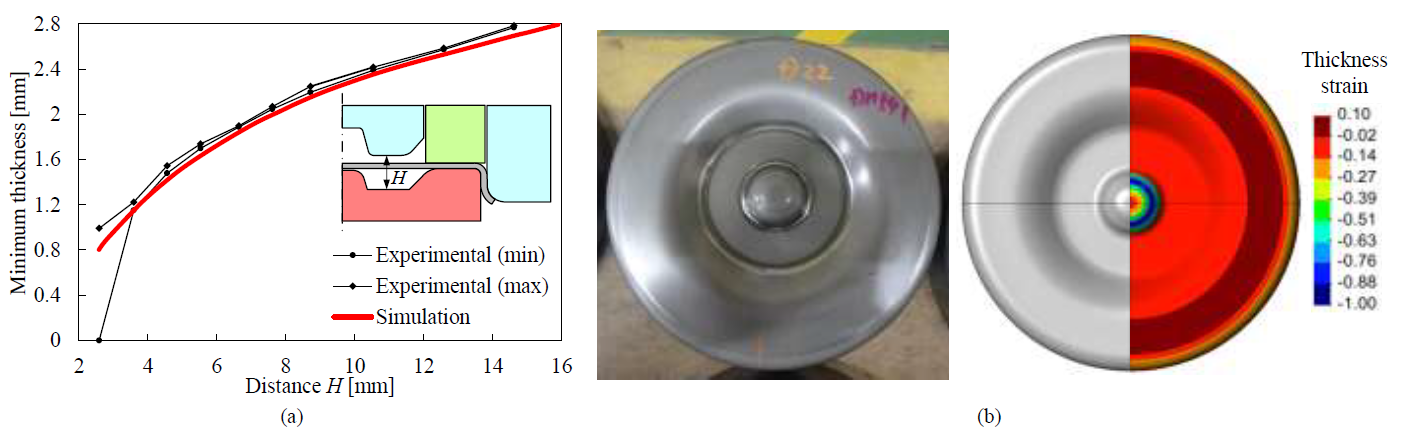
Fig. 8. Comparison between experimental and predicted results in Task 3: (a) evolution of the minimum thickness in the apex of the center boss in function of the distance, H, between the punch and the die; (b) cup geometry and predicted thickness strain for H=3.6 mm.
4 Conclusions
The deep‐drawing of an axisymmetric cup with an embossing operation in the bottom is presented and analyzed, comparing the numerical predictions with the experimental results provided by the benchmark committee of Numisheet 2018 conference [7]. The influence of the orthotropic plastic behavior modelling on the numerical prediction of forming defects is studied, adopting the advanced yield function proposed by Cazacu and Barlat [10] to describe the material anisotropy of the thick steel sheet. Three different conditions are evaluated, which induce different forming defects, namely cup earing, springback, wrinkling and tearing. The earing profile is accurately predicted since the in-plane distribution of both the r-values and the yield stresses is accurately described by the yield criterion. Since the springback is typically slight in axisymmetric cups, the use of an isotropic hardening law leads to an accurate description of this phenomenon. On the other hand, the amplitude of the wrinkles developed in the flange (when no blank holding force is applied) is clearly underestimated by the numerical model. This can be related with the static implicit time integration approach, where sometimes the initiation of the wrinkles requires an initial imperfection. The thinning in the apex of the center boss is accurately predicted by the numerical model, i.e. the difference between experimental and numerical thickness is always inferior to 4%. Besides, the predicted thickness strain is in good agreement with the location of the necking observed in the cup. Finally, it should be mentioned that the material selected presents a small tension-compression ratio of 0.963. Nevertheless, previous results indicate that this has a negligible impact in the prediction of these defects [17].
Acknowledgements
The authors gratefully acknowledge the financial support of the Portuguese Foundation for Science and Technology (FCT) under the projects with reference PTDC/EME-EME/30592/2017 and PTDC/EME-EME/31657/2017 and by European Regional Development Fund (ERDF) through the Portugal 2020 program and the Centro 2020 Regional Operational Programme (CENTRO- 01-0145-FEDER-031657) under the project MATIS (CENTRO-01-0145-FEDER-000014) and UIDB/00285/2020. We also would like to acknowledge the benchmark committee to make available the experimental data used in the present study.
