1 Introduction
The Forming Limit Diagram (FLD) is often used as a failure criterion in sheet metal forming processes, to evaluate the formability of the material. Unlike the approaches based on ductile fracture criteria [1], through the FLD safe, necked or failed points can be distinguished simply considering the level of major and minor strain which the point has reached: the transition from the sound/necking region to the failure one occurs when the critical values (changing according to the strain path) composing forming-limit curve (FLC) are overcome [2]. To determine the FLC accurately, it is necessary to have a nearly frictionless state in the zone of evaluation [3]. This is difficult to achieve.
Sheet metal FLDs are widely obtained using Nakajima or Marciniak methods. These methods require at least five different sample geometries and punch (hemispherical and flat, respectively) to deform the material. Typical limit of these methods is the friction between the punch and the sample, which may affect the accuracy of the FLC [4].
Beside the adoption of strategies based on the Marciniak test [5], a suitable solution is represented by the adoption of a flexible medium (oil) to be used for deforming the blank instead of a rigid punch: in such a way higher levels of strain can be reached before the rupture [6]. The hydraulic bulge test can thus represent an effective way to establish the forming limit diagram (FLD) but limited to the range of positive minor strains. In fact, by varying the aperture ratio of the dies with elliptical apertures, different strain paths can be obtained [7][8][9]. Besides the fact that it is not necessary to have blanks with different shapes, the main advantage of the hydraulic bulge tests is that fluid pressure replaces the punch, thus avoiding friction effects [7][10]. Therefore, data obtained from the hydraulic bulge tests would be purely representative of the formability of the material, compared to the data obtained by forming the blank using a rigid punch. Recently this test was proposed by Banabic et al. [11] for determining the entire deformation range of the FLD. According to this methodology, different strain paths can be obtained merely using a blank having two holes with a suitable geometry and position on the blank to be tested, without the need of dies with elliptical apertures. However, a carrier sheet is necessary, thus implying results may be affected by friction effects.
Local laser heat treatments are often used in order to solve the problem of the poor formability at room temperature of certain materials, such as aluminium alloys [12]. In fact, by using localised heat treatments, it is possible to tailor the distribution of material properties according to the requirements of the forming process [13].
This work aims to evaluate the feasibility of determining the right side of the Forming Limit Curve (FLC), based on the adoption of local heat treatments for determining different strain paths on the test blank while using the classical circular die for bulge tests. In particular, the formability of the alloy AA5754-H32 was investigated; laser heat treatments were used to locally change the material properties with the aim of altering the strain paths during the test. 3D Finite Element simulations were conducted setting different laser strategies and monitoring the resulting strain path. Finally, the correlation between the laser heat strategies and the die aperture ratios for obtaining a particular slope was found.
2 Materials and Methods
2.1 Investigated alloy
The investigated alloy was an Aluminium Alloy (5754-H32) 1.5 mm thick, whose chemical composition is reported in Table 1.
Table 1 Chemical composition of the investigated alloy (AA5754-H32)

2.2 Numerical model of the bulge tests
Figure 1(a) represents a schematic of the bulge test, showing the experimental setup characterised by a die profile radius Rf equal to 10 mm, a sheet radius Rs equal to 125 mm, a radius of the circular die Rd equal to 55 mm and a distance between the shoulder of the die profile and the draw bead Dsd equal to 14.5 mm. This schematic can be assumed valid also for an elliptical die. In this case, the major semi-axis is equal to Rd (55 mm) while the minor semi-axis can be varied depending on the die aperture ratio. A flow stress curve was obtained using circular hydraulic bulge tests, where the instantaneous strain acquisition was recorded using GOM ARAMIS DIC cameras and a force (converted into a stress value) acquired from Zwick-Roell BUP1000 equipment, and it is shown in Figure 1(b).
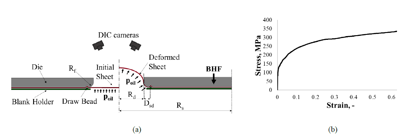
Figure 1 (a) Scheme of the Hydraulic bulge test (b) Flow stress curve obtained from the Hydraulic Bulge Tests
The hydraulic bulge tests were simulated using the commercial software Abaqus. To simplify the numerical model, only a quarter of the setup was considered due to the geometric symmetries; it is shown in Figure 2(a). Moreover, the draw bead was neglected, and its effect was considered by setting a suitable boundary condition. The die cavity and the blank holder were modelled as rigid bodies while the blank as a deformable shell with an initial thickness of 1.5 mm, with five through-thickness integration points. The simulations were performed assuming an incremental increase of the applied pressure on the inner surface of the sheet. To predict the occurrence of failure, the Forming Limit Diagram (FLD) damage initiation criterion was used. The Forming Limit Curve (FLC) for the AA5754-H32 sheets was analytically calculated from the flow curve showed in Figure 1(b) following the procedure proposed in [14]. The implementation of the FLC in the FE model activates an output variable, the FLDCRT, defined as the ratio between the calculated value of major strain and the value of major strain on the FLC corresponding to the same value of the minor strain. The model predicts the occurrence of rupture when the FLDCRT variable overcomes the threshold value equal to 1.
To obtain different strain paths, two different approaches were investigated:
- Conventional approach: elliptical dies with different aperture ratios (a.r.) were used with a standard test sample.
- LHT approach: a standard circular die was used with a “Laser Heat Treated” test sample; where locally selected areas were treated to alter the material properties locally altered.
In the conventional approach, ratios of 0.8, 0.6 and 0.4 (corresponding to minor semi-axis values equal to 44 mm, 33 mm and 22 mm, respectively) were investigated by means of Finite Element (FE) simulations. Here the draw beads were positioned to follow the different ratio changes. In the LHT approach, the heat treatments locally altering the material properties of the test samples were modelled partitioning the sheet. Here, the plastic behaviour of the LHT annealed condition (AA5754-H111) [15] was assigned to regions 10 mm x 10 mm. Between the as received (ASR) and the annealed condition (LHT), a transition region having intermediate mechanical properties was modelled with an offset equal to 2.5 mm from the heat-treated zone (see figure 2(b)).
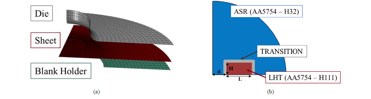
Figure 2 (a) Schematic representation of the FE geometry; (b) Partitions of the test sample for the LHT sheets; d: distance of the laser track from the center of the sheet, L: length of the LHT region; H: height of the LHT region
In order to assess the most suitable size of the annealed zone, FE simulations were conducted, aimed first at evaluating the effect of the three parameters, namely the length (L), the height (H) and the distance of the laser track from the center of the sheet (d) on the strain path at the dome. The above mentioned parameters are shown in Figure 2(b). Thus, a Central-Composite Design (CCD) consisting of 15 runs was adopted for the FE simulations. Low and high level for parameters were 20/50 mm for L, 20/50 mm for H and 10/25 mm for d. Center points of the design were characterized by H= 15 mm, L= 35 mm and d= 15 mm while star points by H= 5/30 mm, L= 10/60 mm, d=5/30 mm. Further simulations were finally performed according to the results from such DOE plan.
3 Results and discussion
3.1 Numerical model validation
The numerical model for a standard bulge test was validated using data from experiments performed with a circular die. Figure 3(a) and Figure 3(b) show the equivalent plastic strain (PEEQ) distribution at failure obtained from the FE simulations and the GOM ARAMIS system acquisition, respectively. Figure 3(c) shows the numerical/experimental comparison of the dome height (ℎ𝑑) evolution during the tests. In particular, the experimental dome height was obtained using the approach given by Panknin [16] as a function of the bulge radius (𝜌) calculated by the GOM ARAMIS system (Equation 1):

In Figure 3(d) the strain path extracted at the dome from the simulation was plotted together with that acquired by GOM ARAMIS. Both graphs show a good correlation between experimental and numerical data.
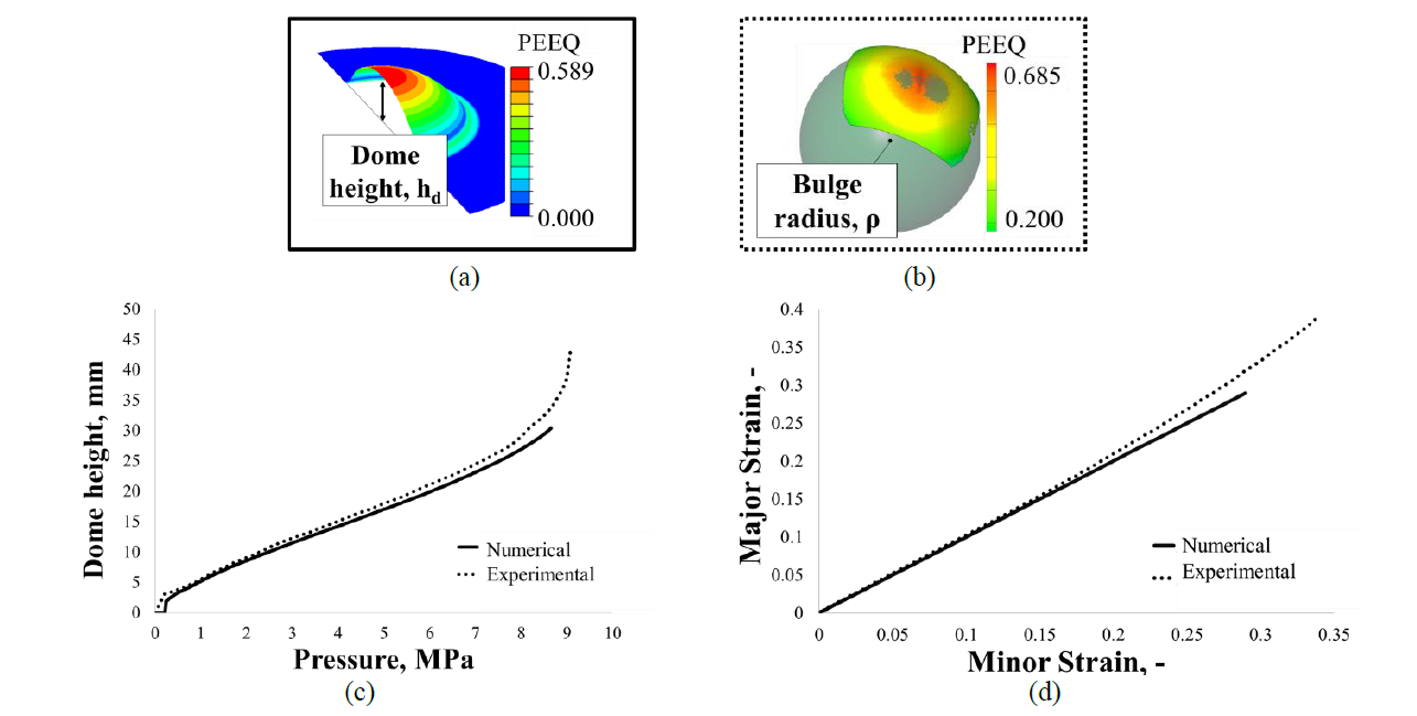
Figure 3 Results of circular bulge tests on ASR sheets: (a) Equivalent plastic strain (PEEQ) distribution at failure obtained from the FE simulations (b) Equivalent plastic strain (PEEQ) distribution at failure acquired by the GOM ARAMIS system (c) Numerical and experimental dome height vs pressure; (d) Numerical and experimental strain paths of the dome.
3.2 Investigation about the parameters of the laser heat treatment
Analysis of variance (ANOVA) was adopted to determine how the size (identified by the parameters H and L) and the position (defined by the parameter d) of the heat treated region affect the strain path at the dome. In particular, the slope of the strain path (Major strain/Minor strain) was considered as response variable. The results of ANOVA are in Figure 4.
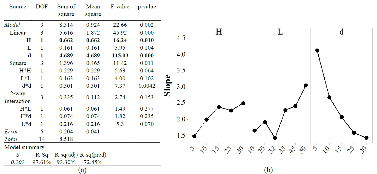
Figure 4 Preliminary FE simulations results: (a) ANOVA table for Response Surface Regression Analysis and (b) Main Effect Plot for the slope of the strain path of the dome
In Figure 4(a) the ANOVA table is presented: the test for significance of regression (p value associated with the model) shows that the influence of the height (H) and the distance from the center (d) of the laser track significantly affect the slope of the strain path, as a p-value less than 0.05 was observed. The graphical representation is shown in the Main Effect Plot (Figure 4(b)). Here, it can be observed that the slope of the strain path is mostly affected by the distance of the laser track from the center of the blank (d) and in particular the slope significantly increases when the distance (d) is decreased. Additionally, the slope is increased by an increment of the height of the laser track (H) from 5 mm to 15 mm, but when H reaches the value of 30 mm the slope is increased slightly.
In order to have what is considered to be a valid test, a tester would want to observe fracture at the top of the dome surface. Figure 5 shows the FLDCRT map resulting from the FE simulation of the bulge test conducted on blanks heat treated using two different set of parameters (H=20 mm, L=50 mm, d=10 mm in fig. 5a; H=15 mm, L= 10 mm, d=15 mm in Fig. 5b).
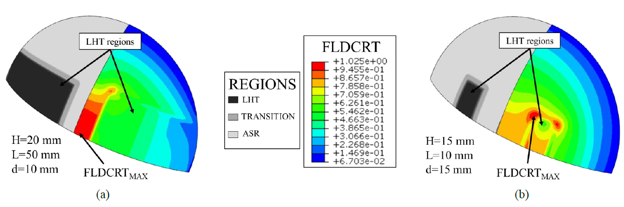
Figure 5 Numerical FLDCRT maps for the LHT condition characterized by (a) H=20 mm, L=50 mm, d=10 mm (b) H015 mm, L= 10 mm, d=15 mm.
It can be noticed that when the heat treated region is sufficiently large (Figure 5(a)), rupture occurred in the top of the dome area (FLDCRT assumed a critical value in the centre before than in any other area); while, when the heat treatment is not large enough, (as in Figure 5(b)), FE simulation results suggest that failure occurs below the top of the dome area.
3.3 Investigation about the strain path modification trough the laser heat treatment
The possibility to modify the slope of the strain path at the dome was investigated varying in a large range (3 – 30 mm) the parameter d, which the results in 3.2 revealed to be the most effective one. The height (H) was kept constant and equal to 5 mm while the length (L) was extended up to the periphery of the blank, in order to limit the occurrence of critical conditions which the simulations put in evidence ( like the one shown in Fig 5b).
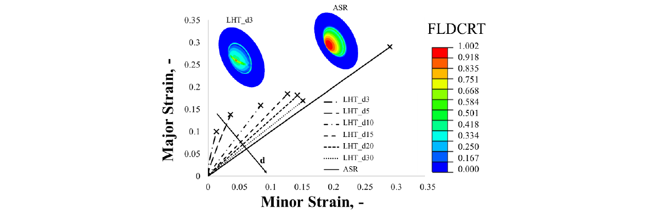
Figure 6 Numerical results in terms of strain paths and FLDCRT maps concerning the bulge tests conducted on heat treated samples
Figure 6 shows the strain paths at the dome of samples in AA5754-H32 which were laser heat treated before the bulge test using different values of the parameter d. In the same figure the FLDCRT maps of the untreated specimen in the as received (ASR) condition and a specimen characterised by the smallest value of the parameter d (3 mm) are shown. Results suggest that if the distance of the laser heat treated zone is decreased from the centre of the sheet, the slope of the strain path at the dome increases, moving closer to the plane strain condition, due to the constraining action exerted by the surrounding material. In addition, it can be observed that the rupture zone is located in the centre.
Figure 7(a) shows the strain paths of the AA5754-H32 dome and the FLDCRT map of the sheets obtained from FE simulations by using the elliptical dies approach. It can be observed that the strain ratio (Major Strain/Minor Strain) increases when the die aperture ratio (a.r.) decreases from 1 to 0.4.
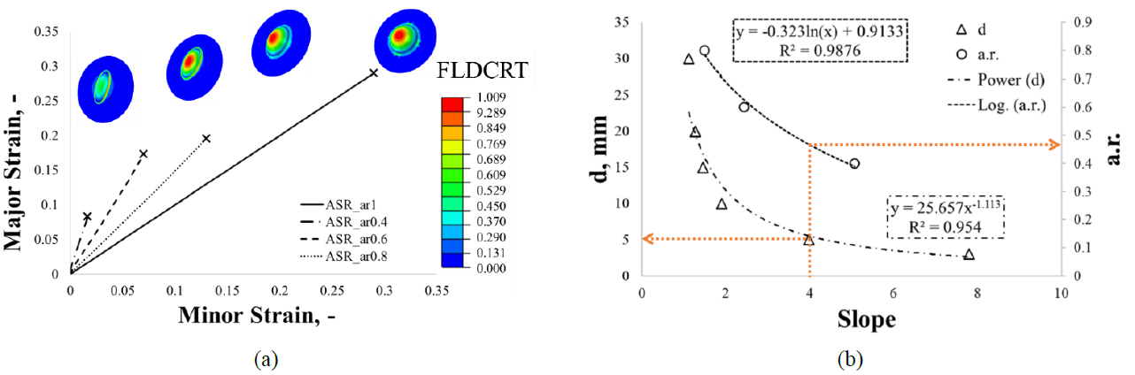
Figure 7 (a) Results of the simulations with the conventional approach; (b) correlation between the two approaches
It is worth noting in the elliptical aperture ratios of 0.4 and 0.6, the simulations predicted an edge failure instead of a failure located on the top of the dome. As reported in [17], in the case of elliptical bulge tests, the die size, the sheet thickness and the material forming properties affect the occurrence of the failure in the dome or on edge.
Finally, Figure 7(b) shows the correlation between the two approaches. Here, the point of the FLC corresponding to a strain path with a slope equal to 4 can be obtained using the conventional approach with an elliptical die with a 0.47 aperture ratio and by using the new approach by conducting a local laser heat treatment characterised by a distance d from the center equal to 5 mm.
4 Conclusions
In this work, a new approach for determining the right side of the forming limit diagram based on the adoption of local heat treatments on the test samples was proposed. Numerical results showed that by modifying the size and position of the laser heat treatment on the sheet, it is possible to achieve a change in the strain path of the dome and in turn investigate the deformation of the FLD in the range of positive minor strains. However, not all the combinations of size and position of the laser heat treatment led to the occurrence of necking and fracture at the dome apex of the specimen. One potential limitation of the proposed approach is that it cannot be used for rolled Al-sheets in the O-condition. But it can be extended to the heat treatable alloys that represent a broad range of materials often used for industrial applications. Future works will be aimed at determining the optimal laser parameters to obtain the desired characteristics on the treated zone. Additionally, understanding the correlation between the mechanical properties of the test sample after the laser heat treatment (hardness and microstructure) and the strain path and the location of the fracture will be investigated using experimental bulge tests on the laser heat treated sheets.
Acknowledgements
This work was supported by the Italian Ministry of Education, University and Research under the Programme “Innovative PhD” (Grant No. CUP - D96C18000840006).
