1 Introduction
The forming limit diagram (FLD) has been a well-established concept to evaluate the formability of metallic materials against necking or fracture. The Nakajima tests with different specimen geometries are typical experiments to determine the FLD of the material. According to the cross-section (CS) method described in the standard (DIN EN ISO 12004-2), the strain field on the specimen surface is recorded, and a parabola function is used to fit the major and minor strain distribution within the fitting window. Though the testing and evaluation procedures are well documented, some drawbacks in the existing methods have driven the development of new approaches for the determination of forming limits.
As the position-dependent method can only be used in cases after the occurrence of crack, various new time-dependent and spatio-temporal methods have been developed by several researchers to obtain a more robust assessment of the forming limits [1]. In these evaluation methods, the evolution history of surface strain distribution is taken into consideration for the determination of the final forming limits. In these methods, the necking moment is determined based on the threshold value of some characteristic parameters, such as the major strain rate, thinning rate, and curvature of the specimen [2-5]. The linear best fitting (LBF) approach developed by Volk and Hora [3] is applied to several different materials with good efficiency and accuracy, which is used in this study as well. The Gini coefficient is a well-known concept in economics used for the assessment of wealth inequality within a nation or group [6]. The Gini coefficient quantifies the degree of deviation of the current distribution from the ideal equally distributed case, where the Gini coefficient is zero. If one person out of a big group is possessed of all the wealth, the Gini coefficient is one in this extremely unequal distribution case. In reality, the Gini coefficient is between zero and one. Forsström et al. [7] used the Gini coefficient to quantify the strain localization in uniaxial tensile tests of weld copper materials. A new method based on the Gini coefficient is developed to evaluate the forming limits of metallic materials as the onset of localization is accompanied by the heterogeneous distribution of plastic strain.
Experimental determination of forming limits is laborious and expensive, and several analytical models have been developed and applied to the numerical prediction of the forming limits of diverse materials [8]. Among these models, the modified maximum force criterion (MMFC) [9] and the Marciniak-Kuczynski (MK) model [10] are widely applied [9, 11-17]. In addition to analytical models, the finite element (FE) simulations using accurate constitutive models are alternatives for the forming limits determination [18]. Various stress states can be generated in flat tensile specimens with different geometries. Therefore, it is also possible to extract the forming limits under various strain paths using tensile tests, especially on the left side of the FLD. In this study, the forming limit curves of a ferritic stainless steel have been determined from experiments and finite element simulations of Nakajima and notched dog bone (NDB) specimens using various evaluation methods. The investigation program is summarized as:
-
Determination of experimental forming limit curve from Nakajima tests using the cross-section (CS) method according to the ISO standard, which is referred as Exp. Nakajima (CS).
-
Simulation of the Nakajima tests using an anisotropic damage mechanics model to obtain the numerical forming limits using both the linear best fitting (LBF) method and the Gini coefficient approach, which are referred as Sim. Nakajima (LBF) and Sim. Nakajima (Gini), respectively.
-
Simulation of the tensile tests of notched dog bone (NDB) specimens using an anisotropic damage mechanics model to obtain the numerical forming limits using both the linear best fitting (LBF) method and the Gini coefficient approach, which are referred as Sim. NDB (LBF) and Sim. NDB (Gini), respectively.
2 Experiments
2.1 Tensile tests
The anisotropic plasticity properties of the AISI 439 steel are determined by performing uniaxial tensile tests using smooth dog bone (SDB) specimens along seven different loading orientations at room temperature under quasi-static conditions. The anisotropic stress vs. strain curves and the evolution history of r-values during tensile tests are provided in [11]. In addition to smooth dog bone specimens, four different notched dog bone (NDB) specimens have been used to characterize the instability and damage behavior under different stress states. NDB specimens with different notch radius (2 mm, 5 mm, 20 mm and 80 mm) have been tested along rolling, transverse and diagonal directions to investigate the anisotropic failure properties. The experimental force and displacement curves of the NDB-R20 specimen are shown in Fig. 1 with apparent anisotropic effects in both plasticity and damage behavior.

Fig. 1. Tensile properties of the AISI 439 steel obtained from (a) smooth dog bone specimens and (b) notched dog bone specimens (NDB-R20)
2.2 Nakajima tests
Nakajima tests have been performed, where flat specimens with eight different geometries with a thickness of 1 mm are used. In the Nakajima tests, the longitudinal axis is along the transverse direction of the material. Grids were electrochemically etched on the specimen surface to track the surface strain. The position-dependent method, also referred to as the cross-section method, is used to determine the experimental forming limit curve using a parabola fitting function following the ISO standard. Detailed information about experimental procedures and evaluation results are provided in [11].
3 Models
An evolving plasticity model has been used to describe the anisotropic plastic deformation behavior, which combines the Hill48 quadratic equivalent stress and the non-associated flow rule [11]. The anisotropic hardening and r-value evolution have been integrated into the evolving plasticity model as well. Based on the evolving plasticity model, an anisotropic damage mechanics model is used to describe the orientation-dependent plasticity and damage properties of the material, which has been utilized to predict the anisotropic ductile fracture of a pipeline steel, where the detailed description of model formulation and parameter calibration is available [19]. Some fundamental equations in the anisotropic damage mechanics model are briefly summarized.

In this evolving plasticity model, anisotropic parameters (𝐹,𝐺,𝐻,𝐿,𝑀,𝑁) in the yield function 𝑓 and the flow potential 𝑔 are calibrated independently as functions of the equivalent plastic strain 𝜀̅p. Anisotropic parameters in the yield function are calibrated based on the stress values, while those parameters in the flow potential are determined using r-values. The plastic strain components are updated according to the non-associated flow rule.

The damage initiation criterion is defined as a critical value of the equivalent plastic strain, which is dependent on both the stress triaxiality 𝜂 and the Lode angle parameter θ̄ [20-22]. A phenomenological symmetric damage initiation locus (DIL) with respect to the generalized plane strain tension plane (θ̄=0) is defined for each loading direction 𝛼, where four parameters 𝐶𝛼1~4 are calibrated independently.

During the plastic deformation, the evolution of stress state variables is also taken into consideration. A linear damage evolution law has been applied to quantify the damage induced softening effects and stimulate the crack propagation. The material model has been implemented as a user-defined subroutine, which is applied to simulate the deformation process in both the tensile tests and the Nakajima tests using the finite element simulation software ABAQUS/Explicit.
4 Results and discussion
4.1 Damage model calibration and validation
Tensile tests of four different notched dog bone specimens have been used to calibrate both the plasticity and damage parameters based on the global force and displacement curves. It is important to take the evolution of anisotropy into consideration in order to achieve an accurate prediction of the mechanical response of this material. The characters of evolving anisotropy have attracted more research attention in the recent development of constitutive models [11, 23-27].

Fig. 2. Experimental and numerical results of force and displacement curves of the AISI 439 steel obtained from: (a) tensile tests of a notched dog bone specimen (NDB-R20) along the transverse direction and (b) Nakajima specimen with a full width (190 mm)
The Swift hardening law has been used to describe the anisotropic flow curves along different loading directions, and a linear function has been used to extrapolate the r-value to a large plastic strain range. The detailed finite element model configurations for the tensile tests with flat samples and the Nakajima tests are referred to in previous studies [19, 28]. The local variables, including equivalent plastic strain, stress triaxiality and Lode angle parameter, are extracted from the critical elements to determine the damage initiation parameters. With the calibrated parameters based on tensile tests, the damage mechanics model is applied to the simulation of Nakajima tests for validation. The predicted global force and displacement curves using the damage mechanics model are compared with experimental results in Fig. 2. The simulation results of tensile tests of the NDB-R20 specimen along the transverse direction are shown in Fig. 2 (a), and the simulation results of the Nakajima tests with a full width (Nakajima-190) are plotted in Fig. 2 (b). From the force and displacement results, it is concluded that the mechanical properties of the investigated AISI 439 steel under different stress states are accurately predicted using the developed anisotropic damage mechanics model [19].
4.2 Evaluation of forming limits
With the accurate description of the global response under various stress states, the surface strain distribution can be accurately reconstructed using the damage mechanics model. In the finite element simulations, a very fine mesh has been applied to reveal the local strain gradients with a high resolution. In order to determine the forming limits from the surface strain distribution, different evaluation methods have been applied to FE simulation results of both the tensile specimens and Nakajima specimens.
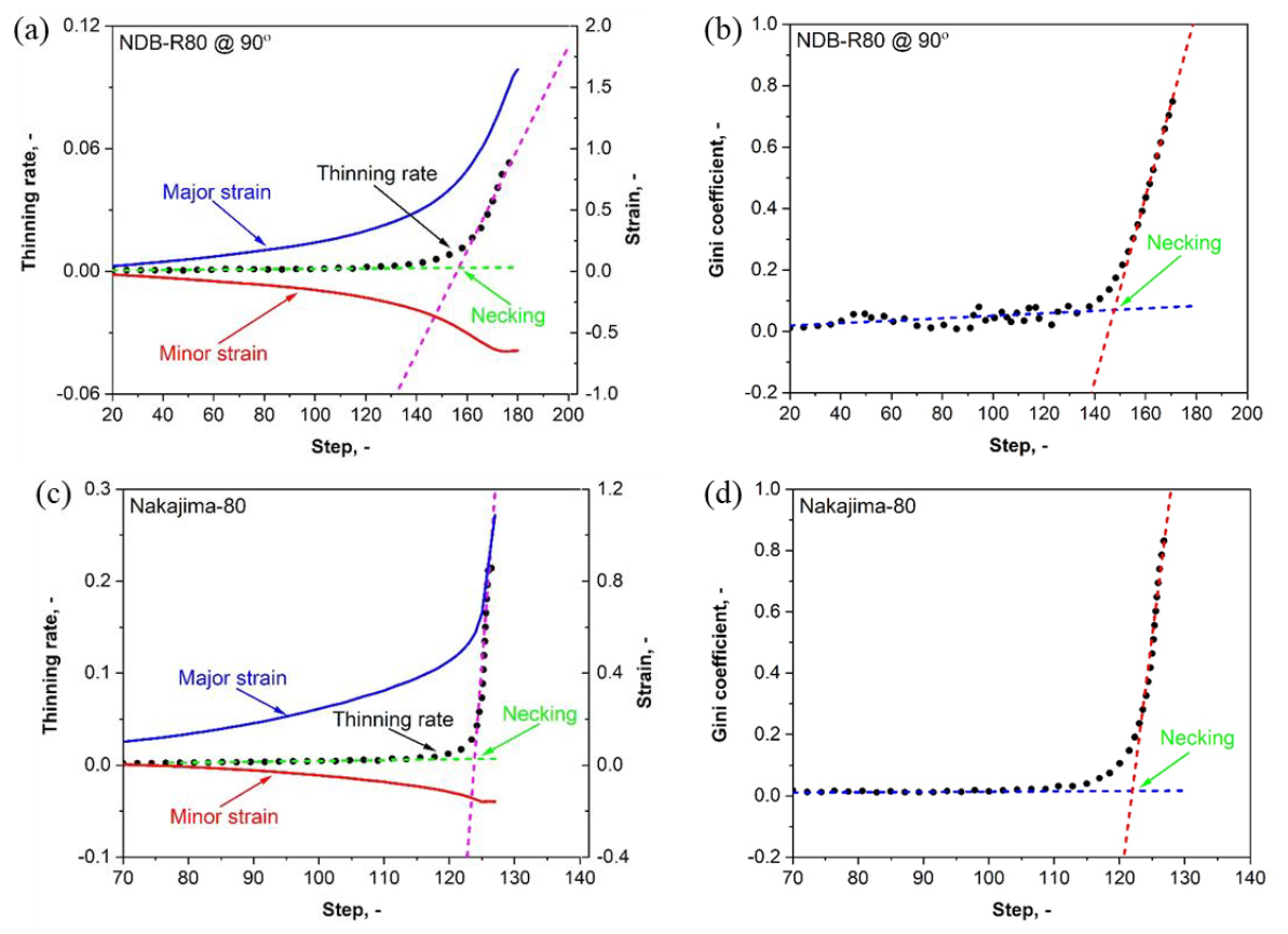
Fig. 3. The schematic demonstration of the LBF method and the Gini method used in the determination of forming limits based on surface strain distribution results obtained from finite element simulations of tensile tests and Nakajima tests. (a) The LBF method with a NDB-R80 specimen, (b) the Gini method with a NDB-R80 specimen, (c) the LBF method with a Nakajima specimen and (d) the Gini method with a Nakajima specimen
The LBF method and the Gini method are schematically demonstrated using two representative geometries in Fig. 3. The NDB specimens are loaded along the transverse direction. The thinning rate, the absolute value of the thickness strain rate, in the necking region is increasing rapidly after a phase of homogeneous deformation. The necking moment is determined as the intersection point of two linear fitting curves, as shown in Fig. 3 (a) for the NDB-R80 specimen and Fig. 3 (c) for the Nakajima-80 specimen, respectively. Due to the increase of inhomogeneity in plastic deformation, the accumulation of plastic strain is localized into a small region with a limited number of elements after the onset of necking. The localization in plastic deformation leads to an increase in the inequality in the thinning rate distribution, which is represented as an increase in the Gini coefficient. The intersection point of two linear fitting curves describing the evolutionary history of the Gini coefficient is recognized as the necking moment, as shown in Fig. 3 (b) for the NDB-R80 specimen and Fig. 3 (d) for the Nakajima-80 specimen, respectively.
The linear best fitting method and the Gini coefficient evaluation method have only been independently used to determine the forming limit curves based on the finite element simulation results of tensile tests of notched dog bone specimens and Nakajima tests. The numerically determined forming limits based on finite element simulations are compared with experimental results obtained from Nakajima tests using the cross-section (CS) method according to the ISO standard, as shown in Fig. 4. The results determined based on the LBF method are shown as solid and empty blue pentagrams for Nakajima and NDB specimens, respectively. The results determined using the new Gini coefficient method are shown as solid and empty red circles for Nakajima and NDB specimens, respectively. The forming limits evaluated based on FE simulation results of Nakajima tests using the LBF and Gini methods are consistent with each other, especially on the right side of the FLD. A slight difference is observed in the results when the stress state is close to the uniaxial tension condition. Only the forming limits on the left side of the FLD can be determined using tensile tests of NDB specimens with different notch geometries. Based on the LBF method, the forming limits determined from tensile tests are in line with the results from the Nakajima tests. The forming limits evaluated using the new Gini method are in good agreement with experimental results as well. Both tensile specimens and Nakajima specimens can be used to evaluate the formability of the sheet material in combination with the Gini approach. In comparison with the LBF method, the forming limits derived from the Gini coefficient approach are more conservative on the left side of the FLD. It is noticed that the final forming limits determined using the time-dependent methods are sensitive to the size of the investigation region in the specimens. Therefore, a systematic investigation on the sensitivity of the developed forming limits evaluation method to several influencing factors needs to be conducted.
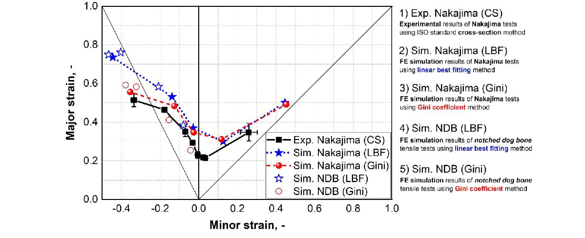
Fig. 4. The forming limit curves determined by different evaluation methods for the AISI439 steel based on tensile tests of notched dog bone specimens and Nakajima specimens
5 Conclusions
The cold formability of a ferritic stainless steel has been evaluated by performing tensile tests and Nakajima tests. An anisotropic damage mechanics model is used to describe the plasticity and damage properties of the material using finite element simulations. A new spatio-temporal method based on the Gini coefficient concept is developed to describe the localization behavior and determine the forming limits. Different evaluation methods have been adopted for both tensile tests and Nakajima tests to determine the forming limits of the material. Based on the experimental and numerical results, some conclusions can be drawn:
-
The pronounced anisotropic plasticity is accurately captured by an evolving plasticity model, which is capable of describing the anisotropic hardening and r-value evolution in the framework of the non-associated flow rule.
-
An anisotropic hybrid damage mechanics model is adopted to accurately predict the orientation-dependent damage and fracture properties of the material. In the damage mechanics model, the effects of stress triaxiality, Lode angle parameter, loading orientation, and stress state evolution are taken into consideration.
-
The time-dependent linear best fitting method can derive accurate results of the forming limits from both tensile specimens and Nakajima specimens.
-
A new forming limits evaluation method is developed, in which the inequality of plastic deformation is quantified by the Gini coefficient, and the sudden increase of the Gini coefficient indicates the onset of necking. This method has been verified in both tensile tests and Nakajima tests, where comparable results are determined.
-
A slight difference in the forming limits between the Nakajima tests and the fracture tensile tests is revealed based on the consistent evaluation methods as well as the simulation data. This could be resulted from the different loading modes in the thickness direction in the investigated region, for which Nakajima tests typical feature a bending deformation, while fracture tensile tests do not.
